


Scary small.
How about this contactor. Telemecanique LC1 D09 Contactor LC1D09 25A 24V Coil | eBay 1 NO contact to cut AC power to the servo PS and 1 NC contact for the power resistors. Is it ok to only break one leg of the AC power to the PS?
Thread: Tree Journeyman 320 B Retrofit
Results 81 to 100 of 179
Hybrid View
-
02-17-2012, 04:39 PM #1
 Registered
- Join Date
- Apr 2007
- Posts
- 521
-
02-17-2012, 05:08 PM #2
Community Moderator
- Join Date
- Dec 2003
- Posts
- 24260
I usually get the 3ph contactors for the extra contacts for spindle etc.
I believe that coil is 24vac also, in case you were looking for DC?
Also all the telemecanique relays have the option of fitting multi-auxiliary contacts that clip onto the front operator.
Al.CNC, Mechatronics Integration and Custom Machine Design
“Logic will get you from A to B. Imagination will take you everywhere.”
Albert E.
-
02-20-2012, 05:58 PM #3
Registered
- Join Date
- Apr 2007
- Posts
- 521
Thanks for the input guys. After looking at your setups I think I'm pretty clear on the estop/limits/etc set up. There are existing relays on the machine for this purpose. I'm going to use a separate contactor to open the AC supply to the servo PS and to connect the servo braking resistors because the drives/ps are in a separate compartment of the electronics cabinet.
How about this: eBay - New & used electronics, cars, apparel, collectibles, sporting goods & more at low prices 24VDC coil, 20A 2 NO, 2 NC contacts
EDIT: Here is the info from the ebay auction so people can learn from Al's post below after the auction is gone.
Up for sale is a brand new never used SH4 positive guided relay from AEG.
Unit comes in its original box.
Specs:
Part# SH4.22-NSW
Contacts: Rated 20 Amps
2 Normally open, and 2 Normally closed poles
Coil: 24Vdc
Positive guided design, assures that no normally open contact can close before any normally closed contact can open. Per IEC947-5-1 requirements.
UL/ CSA/ CE approved.
Dimensions: 1 3/4" W x 3 1/16" H x 2 7/8" D
-
02-20-2012, 06:07 PM #4
Community Moderator
- Join Date
- Dec 2003
- Posts
- 24260
That contactor relay has Force-Guided contacts which essentially makes it a safety relay that is the basic design of all safety relays where they are mandatory, so that one has a bit of an edge over the normal contactor.
BTW, the E-stop string should NEVER be a result of PLC logic, the mandatory code is always hardwired logic, with the end result being preferably a Safety Relay.
Al.CNC, Mechatronics Integration and Custom Machine Design
“Logic will get you from A to B. Imagination will take you everywhere.”
Albert E.
-
02-20-2012, 06:12 PM #5
Registered
- Join Date
- Jul 2003
- Posts
- 1766
Agreed. My estop loop is hardwired. The plc logic just allows emc to see and reset the loop. (once the loop is complete again)
sam
 Originally Posted by Al_The_Man

-
02-20-2012, 08:32 PM #6
Registered
- Join Date
- Apr 2007
- Posts
- 521
The wiring continues...
Quick question. The AMC drives have +REF IN and -REF IN as the analog inputs. The 7i48 has AOUT0 as the analog output (with GND0 next to it). The 7i48 manual says:
How do I hook this up?ANALOG OUTPUTS
The analog output of the 7I48 swings from -10 v to +10V. Positive outputs are
generated when PWM+ is input is driven, and negative outputs when PWM- is driven. A
50 % duty cycle PWM signal will generate a 5V output. This mode of operation require the
PWM generator be set for "up/down" mode. Due to power supply limitations, The 7I48 has
limited DC output drive capability and should not have loads of less than 3K Ohms on its
analog outputs. (~24 mA maximum total +-10v current). To avoid power supply damage,
do no short more than one analog output at once.
-
02-20-2012, 08:39 PM #7
Community Moderator
- Join Date
- Dec 2003
- Posts
- 24260
AOUT0 - +REF
GND0 - -REF
The AOUT0 swings from +10 to -10 WRT to GND0
Al.CNC, Mechatronics Integration and Custom Machine Design
“Logic will get you from A to B. Imagination will take you everywhere.”
Albert E.
-
02-20-2012, 08:41 PM #8
Registered
- Join Date
- Apr 2007
- Posts
- 521
Thanks. That's what I assumed but you know what they say.
-
02-21-2012, 11:14 PM #9
Registered
- Join Date
- Apr 2007
- Posts
- 521
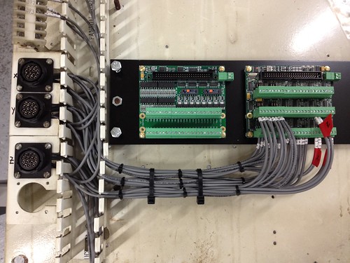
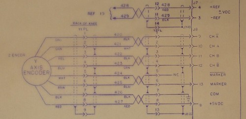
I started wiring the amp connectors to the MESA 7i48. These are the encoder and REF wires. The connectors also have the home switches.
There are two shield wires on each connector for example Y2PL pins 13 and 14 which don't look like they were connected to the original controller. What should I do with them?
-
02-21-2012, 11:34 PM #10
Community Moderator
- Join Date
- Dec 2003
- Posts
- 24260
13 & 14 look like they carried the drain wire or shield through the connector?
Do your encoder wires have shields? If they come into the CPC connectors, you would normally terminate these with wires to the common ground point.
Al.CNC, Mechatronics Integration and Custom Machine Design
“Logic will get you from A to B. Imagination will take you everywhere.”
Albert E.
-
02-22-2012, 11:06 PM #11
Registered
- Join Date
- Apr 2007
- Posts
- 521
I cant tell if the wires have shields because they are inside conduits and jackets. Looking at the wiring diagram it looks like 13 and 14 are connected to the shields. I'll wire the shields together near the amp connectors and then one bigger wire to the main ground point?
-
02-23-2012, 03:35 AM #12
Community Moderator
- Join Date
- Dec 2003
- Posts
- 24260
That should work if you don't have a pin to continue them through the CPC connectors, as long as they anchor to ground or even the chassis point.
Al.CNC, Mechatronics Integration and Custom Machine Design
“Logic will get you from A to B. Imagination will take you everywhere.”
Albert E.
-
03-21-2012, 06:20 PM #13
Registered
- Join Date
- Apr 2007
- Posts
- 521
Hi Everyone,
Work has been busy and I haven't spent any time on the mill retrofit in the last month.
I'm still struggling with the enable for the servo amps. Here are the relevant parts of the manuals:
b30a8 servo drive manual:
7i48 manual:TTL level (+5 V) inhibit/enable input. Leave open to enable drive. Pull to ground to inhibit drive. Inhibit turns off all power devices.
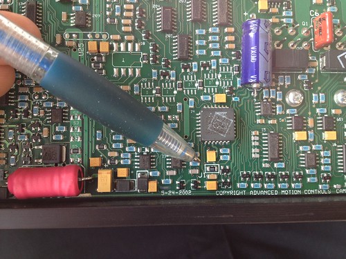
I talked to AMC tech support and they confirmed that it is the J1 jumper I need to remove to invert the inhibit logic of the drive. If I invert the logic open will be disabled and I can have the 7i48 pull the inhibit pin to ground to enable. Any tips on surface mount jumper removal? (see picture in post 79)Each 7I48 channel has a OPTO-isolated transistor output that can be used to
enable external amplifiers. All six outputs are on when both input enable signals are low,
that is all enable outputs are switched at once. Maximum switched voltage is 36VDC.
Maximum output current is 10 mA. Even though all outputs are switched in common, they
are all isolated to allow different enable connections on a per amplifier basis.
Example connections:
1. Active high 12V amplifier enable on ch 0:
Connect ENA0+ to +12V source
Connect ENA0- to amplifier enable input
2. Active low TTL input
Connect ENA2- to ground
Connect ENA2+ to amplifier enable input
-
03-21-2012, 07:24 PM #14
Junior Member
- Join Date
- Sep 2005
- Posts
- 322
That looks like a surface mount resistor in the pic, not a jumper.
If it's meant to be able to be changed, then there should be a plastic jumper you can pull/set with a pair of tweezers, and it won't require desoldering.
Unless I misunderstand my electronics terminology however, can't you just connect one side of the 7i48 card's pins to ground and the other to the servo amp enable pin? Wouldn't the card then close that connection when it flips the enable output to "on", attaching the servo amp pin to ground?
I may be wrong, it's been hard to wrap my head around how Mesa's output pins work.
Erik
-
03-21-2012, 07:33 PM #15
Registered
- Join Date
- Apr 2007
- Posts
- 521
Hi Erik,
It is basically a surface mount resistor with a resistance of 0. I think previous models of this drive had the plastic jumper you describe but they went to this probably so they can use a pick and place machine.
As I understand it the current inhibit logic needs an + or open to enable and - to disable. I think I could use a biggish resistor to pull the inhibit pin to ground and then use the mesa board to pull it high to enable. This may actually be a good option instead of trying my hand at surface mount desoldering.
-
03-21-2012, 07:59 PM #16
Community Moderator
- Join Date
- Dec 2003
- Posts
- 24260
Yes it is just a 'Resistor link' with 0 ohms, I have just use a soldering iron to lift it off the board, or if gentle you can snip it with small wire snippers.
According to how I interpret the 7148 instructions it works with either logic, but it is poorly explained.
The normal default for the AMC is open is enabled, it is taken to common to disable.
Al.CNC, Mechatronics Integration and Custom Machine Design
“Logic will get you from A to B. Imagination will take you everywhere.”
Albert E.
-
03-21-2012, 08:09 PM #17
Junior Member
- Join Date
- Sep 2005
- Posts
- 322
Ah, okay.
I've removed SMDs in the past with a little soldering iron heat. Typically SMDs are installed with a paste solder, which has a little lower melting point than the coil stuff.
You could probably just touch both ends with an iron and lift it off. I'd recommend avoiding it though. Maybe use an inverter TTL chip on a separate board?
Erik
-
03-22-2012, 03:47 PM #18
Registered
- Join Date
- Apr 2007
- Posts
- 521
I emailed Peter at Mesa for advice on how to configure / wire the enable circuit.
-
03-22-2012, 05:12 PM #19
Registered
- Join Date
- Jul 2003
- Posts
- 1766
IIRC all of our amps have the jumper installed... Going from memory then - a +5 v on the inhibit pin would enable the drives. (because they where inhibit with the line above or 'inhibit - not')
Again - going from memory...
-
03-22-2012, 07:11 PM #20
Registered
- Join Date
- Apr 2007
- Posts
- 521
Samco - I dont understand. I think there is an internal pullup on the inhibit pin so open or +5VDC to enable and 0VDC to disable.
More questions:
There are 4 pins on the 7i48 that connect to the drive:
ENA0-
ENA0+
GND0
AOUT0
On the drive these are the pins I think I need to use
4 +REF IN
5 -REF IN
8 CURR MONITOR OUT (I may use this later)
9 INHIBIT IN
11 GND
16 FAULT OUT
Two questions:
1) I'm pretty sure GND0 --> -REF IN and AOUT --> +REF IN
Where does the GND on the drive connect to?
2) Fault monitoring. I want to add circuitry so that a fault in one of the drives (FAULT OUT goes to +5VDC) opens the estop chain which will be +24VDC. Al mentioned using a ULN2803 IC anyone have info on that or a different solution.

 Reply With Quote
Similar Threads
-
Journeyman 325 tree mill retrofit
By ramsey321 in forum TreeReplies: 13Last Post: 09-25-2020, 03:18 AM -
Tree Journeyman 300
By hjl4 in forum TreeReplies: 2Last Post: 08-21-2011, 06:18 AM -
Tree journeyman 325 servo retrofit
By red zilla in forum TreeReplies: 2Last Post: 06-22-2011, 04:19 AM -
Tree Journeyman 250 CNC
By tommy tr in forum MetalWork DiscussionReplies: 3Last Post: 04-01-2007, 08:55 PM -
Tree Journeyman 310 and VFD
By Provectus in forum TreeReplies: 5Last Post: 01-27-2007, 04:13 AM
