


My smaller steel frame machine may have a chance of doing it. ACME screw accuracy over that small distance should be ok if the DumpsterCNC nuts are up to it. Everything else should be plenty tight enough.
CarveOne
Results 161 to 180 of 645
-
01-22-2012, 12:39 PM #161
 Member
- Join Date
- Apr 2007
- Posts
- 8082
CarveOne
http://www.carveonecncwoodcraft.com
-
01-23-2012, 06:41 AM #162
Gold Member
- Join Date
- Apr 2009
- Posts
- 5516
C1 I wouldn't worry about the accuracy as much, as long as you have very little backlash, you should be able to do it fine!
Jerry, looks good! And a .023" ballmill in a 3HP spindle is not uncommon; heck the big VMCs can do it with 30HP+ spindles! Check this video out about 2:36 in...
[ame=http://www.youtube.com/watch?v=0LCaRqQ8Qf8]Matsuura Maxia: 5 Axis Unmanned Multi Pallet Machining - YouTube[/ame]
-
01-23-2012, 07:02 AM #163
Registered
- Join Date
- Aug 2011
- Posts
- 999
Oh dear....heavy duty stuff. But I would rather use a dental spindle with 50,000+ rpm with these small bits. For the roughing end mill I tried first 20 ipm then 10 ipm and only at 5 ipm the bit did not break. Fortunately these small carbide bits are only $3 each.....If my machine would allow for lubrication/cooling fluid that might help, too. But that would be a bloody mess. Originally Posted by louieatienza

Reminds me that the company I work for makes some really fancy CNC machines in another division. Maybe I just asks the colleagues over there in Switzerland if they have a trade show sample left over")
-
01-24-2012, 06:33 PM #164
Registered
- Join Date
- Jan 2007
- Posts
- 117
Something Really Small
The belly button looks great, but the nips still need a little work.
Seriously, Went through your thread for the first time today. Fantastic machine with incredible precision. I'm amazed at the constant stream of ingenuity here at the Zone. Bamboo Ply? Who would've thunk it.
I have built a number of small parts using scraps from bamboo flooring and stair parts. It machines better than just about every material I've worked with (has a pleasant smell too) . Didn't know the plywood was available.
Kuroda screws are incredible. I'm starting construction of a new machine using a manufactured Kuroda linear actuator for the X (gantry) axis. The specs state that the repeatability across 3 1/2 feet of travel is +/- 3 microns. You're probably getting something close to that on your machine. Light years beyond the precision of a R&P or belt driven scheme.
I'll be interested to hear how the Chinese spindle is holding up after many hours of use. How many hours do you have on it now?
-
01-24-2012, 09:28 PM #165
Registered
- Join Date
- Aug 2011
- Posts
- 999
Thanks for taking the time to read through all my ramblings

yes I am quite happy with them. I have the GG type screws, C5 grade with <5 micron (0.0002") backlash and about 30 micron lead accuracy over 1100mm length (if I read their specs correctly). And I believe I got them at a good price, something like $120 each for new and unused surplus. Originally Posted by Clockwork
I had maybe 15-20 hours on my previous 1.5kW spindle, no trouble but only very light duty. Originally Posted by Clockwork
I have only a few hours on my new 2.2kW spindle. So far looking good but I did notice I can hear it spin by hand unlike the old smaller one. I hope that is just the grease squishing in the bearings.
-
01-29-2012, 03:43 AM #166
Registered
- Join Date
- Aug 2011
- Posts
- 999
Dust protection
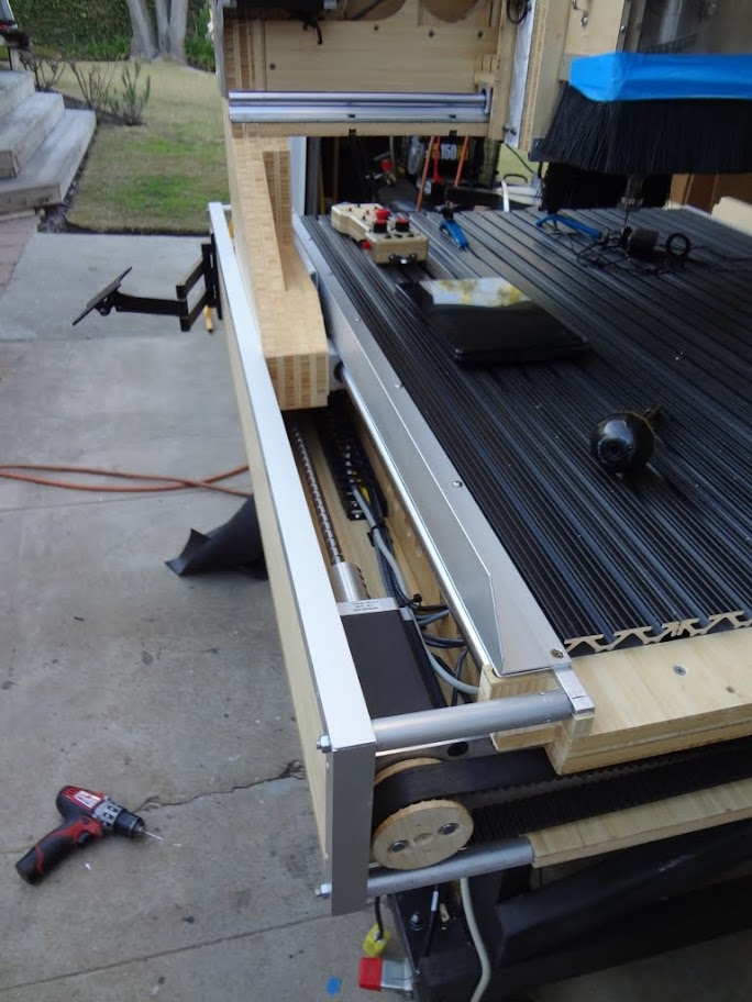
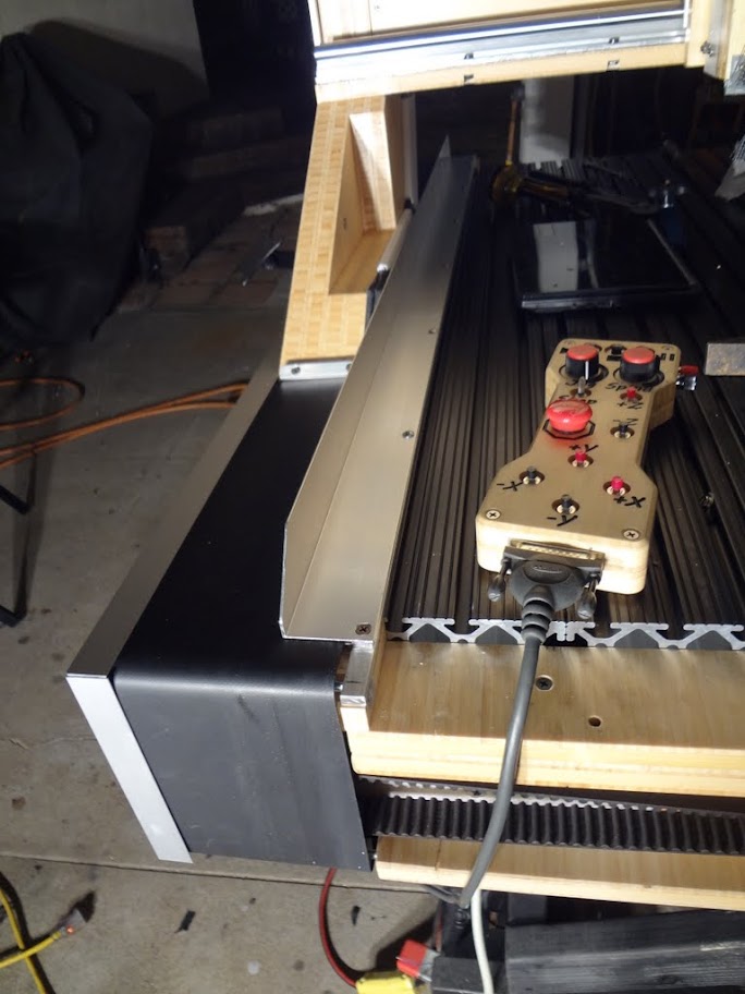
I stopped playing and making parts with the new machine to wrap up remaining work. I was especially worried getting dust gunk buildup in the ball screws.
Today I finished the left side x-axis ballscrew and linear bearing protection. Since I don't have the space for bellows I designed a kind of "moving curtain" style belt cover, that runs in slot guides and over 4 rollers with ball bearings around the machine table, see pics below. All the detail work took me more time than expected but it seems to work well. Next will be the other X-ballscrew and then a similar system for Y (that will however need to spool the belt on both sides). Z-axis is already completely encapsulated.
Additional benefit....I think the machine looks much more "finished" this way ;-)

-
01-29-2012, 06:05 AM #167
Registered
- Join Date
- Jan 2008
- Posts
- 853
That's very cool Jerry. What is the curtain made from?
-
01-29-2012, 06:21 AM #168
Registered
- Join Date
- Aug 2011
- Posts
- 999
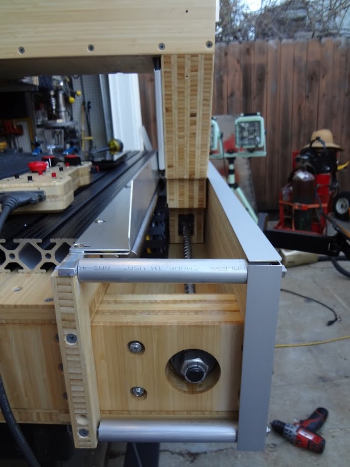
If I only knew...I bought a roll of that stuff a long time ago from McMaster. I believe it was neoprene coated polyester fabric, maybe 40/1000 thick. Originally Posted by PaulRowntree
But any coated fabric or other strong film would do. I had even considered transparent PVC film with the advantage of still seeing what is going on inside but since I had the material I just used it.
-
01-29-2012, 03:31 PM #169
Registered
- Join Date
- Oct 2005
- Posts
- 2392
Very nice Jerry! That's both innovatively designed and very functionally implemented.
Impressive.
-
01-29-2012, 03:38 PM #170
Community Moderator
- Join Date
- Mar 2003
- Posts
- 35538
That is very cool indeed.
However, you will get dust in there, and you'll probably need to periodically clean it out. How often depends on how good your dust shoe works, and how much you use the machine.
Great idea, though.
Gerry
UCCNC 2017 Screenset
http://www.thecncwoodworker.com/2017.html
Mach3 2010 Screenset
http://www.thecncwoodworker.com/2010.html
JointCAM - CNC Dovetails & Box Joints
http://www.g-forcecnc.com/jointcam.html
(Note: The opinions expressed in this post are my own and are not necessarily those of CNCzone and its management)
-
01-30-2012, 04:40 AM #171
Registered
- Join Date
- Aug 2011
- Posts
- 999
You are right, I will have to check this once a while. I still have a trick up my sleeve: I am planning to install a 120V large computer fan under the table box that will blow HEPA filtered air into the enclosed lead screw area (similar for the Y-axis). Main purpose is to make sure the steppers get some cooling but I hope the positive air flow from inside out will also help keep fine dust particles away. Not sure if that will help but I will find out. Originally Posted by ger21
In the meantime I found what I used for the belt: It is 40 mil Neoprene coated Nylon fabric, McMaster # 8811K561
-
01-30-2012, 08:34 PM #172
Registered
- Join Date
- Oct 2005
- Posts
- 2392
Jerry that is a great idea but I don't think a PC fan will generate any significant pressure differential to keep the dust out.
We used that system to good effect in industry on electronics panels but we used a tiny bleed valve to a compressed air system, which was about 50 PSI. It worked because the panels had rubber seals and would get a small pressure rise until the air started to bleed out a seal somewhere.
Since your moving system doesn't have good seals and a PC fan won't make any PSI into a closed cavity I think you will still get dust ingress as the moving curtain physically forces some dirt in.
Maybe a maintenance solution is best? You could cut a few inspection holes on the outer wall and use an occasional blow out with the compressed air. For convenience you could hold the covers on with tiny magnets so it's effortless to remove them and give a squirt with the air gun.
-
01-31-2012, 12:31 AM #173
Registered
- Join Date
- Aug 2011
- Posts
- 999
Yes I am a bit skeptical myself and if any it may only help against light floating dust. The worst case is probably when I blow off the machine with an air nozzle for cleaning, that would surely force some dust inside. Originally Posted by RomanLini
But, in any case I expect this to be 99% better than having open lead screws where all kinds of wood and metal debris will rain down on the screws and get trapped in grease.
I can slide the belt off when I remove 2 screws and have an occasional peek inside.
-
01-31-2012, 05:52 AM #174
Registered
- Join Date
- Jan 2008
- Posts
- 853
Would a centrifugal squirrel/mouse cage fan be able to provide more positive pressure than the axial fan? A bit bigger, a lot noisier, but if it works ...
-
02-01-2012, 07:04 AM #175
Registered
- Join Date
- Aug 2011
- Posts
- 999
Probably...but I should make sure that I am not going overkill here. If most of the dust is kept out and I just clean up the protected area once a while I should be good. The fans are mainly there to achieve a modest air flow for the steppers (which are NEMA34 and don't get that hot). If the fans help keeping dust out, even better. Originally Posted by PaulRowntree
-
02-08-2012, 06:37 AM #176
Registered
- Join Date
- Aug 2011
- Posts
- 999
I know that may be a bit anal but I really wanted to know how accurate my machine is and so I coughed up 60 bucks for a decent [ame=http://www.amazon.com/gp/product/B001DC96YK/ref=oh_o02_s00_i00_details]high resolution indicator[/ame].
Maybe not a super professional accuracy measurement device yet but with 1 micron resolution about as good as I will ever need. I did a quick test and noticed it will measure even pushing my finger lightly against the spindle.
So far I measured the actual backlash (i.e. the whole drivetrain with screw backlash and linear bearing play and wiggle) is about 11 microns or 0.0004" in the middle of the table. Returning to zero (same direction therefore no backlash) is typically better than 5-8 microns. I think that is quite good for a wood frame machine (actually a grass frame machine....). I will sometimes rig up a more sophisticated measurement to establish the actual rigidity under load and play in all directions.
-
02-08-2012, 09:09 AM #177
Registered
- Join Date
- Oct 2005
- Posts
- 2392
That's a cool looking dial tool, and some nice backlash figures you got there too!
Flex will probably be a lot more than your no-load backlash, like when the tool is cutting and puts a few pounds side force on the tool etc. You can simulate by putting a string over the edge of the table and hanging a few pounds from it and tying the other end to the spindle collet, and seeing what the flex and/or loaded backlash figure is then.
Also if your leadnut seals are new and hard they will soak up most of the backlash when there is no load.
It's hard trying to dial in the right compensation for flex and backlash. On my little machine I use different settings depending on the job type. With a tiny tool and low side force I use the full backlash comp, with a larger tool that makes more side force I turn the comp off or reduce it a lot, as the tool forces translate into vibration and not backlash (so increases the effective tool diameter by 1 or 2 thou, but there is no backlash).
If you want to measure dynamic backlash when cutting something I devised a test shape, you can measure it with a micrometer. It's shown in my build thread;
http://www.cnczone.com/forums/cnc_wo...ll_router.html
about half way through the thread.
-
02-08-2012, 05:49 PM #178
Community Moderator
- Join Date
- Mar 2003
- Posts
- 35538
I've heard a Bridgeport will move a few thousandths if you just lean against it.I did a quick test and noticed it will measure even pushing my finger lightly against the spindle.
Gerry
UCCNC 2017 Screenset
http://www.thecncwoodworker.com/2017.html
Mach3 2010 Screenset
http://www.thecncwoodworker.com/2010.html
JointCAM - CNC Dovetails & Box Joints
http://www.g-forcecnc.com/jointcam.html
(Note: The opinions expressed in this post are my own and are not necessarily those of CNCzone and its management)
-
02-08-2012, 07:32 PM #179
Registered
- Join Date
- Aug 2011
- Posts
- 999
That would not be surprising. If you just measure precisely enough, even a very rigid/massive machine will show some movement. With some earlier tests I found my machine to have a pretty decent rigidity of about 5,000-10,000 lbs/inch. But that means it needs less than a pound of force to show a few micrometer displacement on this indicator. Originally Posted by ger21
I am planning to rig a measurement with a fishing scale and plot the difference between the dial indicator reading and the CNC controller display (i.e. position error) vs. the load in 4 directions. That should give a good picture of the backlash/hysteresis and the rigidity as well. Problem is right now I have an electronic luggage scale that always turns off after 30 seconds and I need to get a simple analog one that keeps reading.
Obviously all that is serious accuracy overkill for the wood routing and carving that I want to do with this machine. But I never claimed this has to make practical sense
-
02-09-2012, 01:20 PM #180
Registered
- Join Date
- Oct 2005
- Posts
- 2392
Just throw a string over the edge of the machine and hang a known weight from it. It's a very effective way to generate a known side force. Originally Posted by JerryBurks

 Reply With Quote
Similar Threads
-
7 x 10 project started
By blades in forum Mini LatheReplies: 125Last Post: 01-25-2017, 05:27 AM -
CNC Project Started
By NotSqueaky in forum CNC Wood Router Project LogReplies: 8Last Post: 09-10-2014, 12:41 AM -
New Project Started
By Rumblebelly5 in forum Joes CNC Model 2006Replies: 1Last Post: 09-15-2012, 10:50 PM -
My 4x8 project has started
By MetalHead6263 in forum Plasma, EDM / Other similar machine Project LogReplies: 37Last Post: 01-31-2012, 07:30 AM -
Started new project
By rustamd in forum DIY CNC Router Table MachinesReplies: 55Last Post: 05-31-2009, 04:12 AM
