


Hello everyone,
welcome to yet another Momus build thread, this is my 1st though.
This one is going to be a little bit crazy and perhaps overly ambitious, but please enjoy... :-)
First of all: *** Thank you, Bob! ***
Your Momus is great platform that is just awesome in may ways, not just in functional aspects but also economical to build.
What I am trying to do with this machine is to come up with a specialized Momus that make it into a tool for tasks that a common woodworker runs into all the time, and perhaps some more!
One of these things is end grain routing, to easily make CNC joinery elements, such as dove tails and finger joints, etc.
If you're not sure what that entails, this is where the workpiece is sitting vertically inside the machine, instead of laying it flat onto the spoilboard.
This requires an opening in bottom of the machine bed to insert the workpiece from underneath the machine and clamp it there securely.
I also want to utilize the machine to do bigger carving jobs, such as making signs, etc., so it had to become much longer than the original.
Currently, I'm still going for the belt driven approach on the x-axis, to see how that works out in terms of repeatability with a Kevlar belt, but I've already looked at other options.
Perhaps a Bell-Everman drive or a spindle, this will be a retrofit later on.
Another thing I wanted to be possible within the cutting envelope was a way to do full "in the round" carvings. Think pens and garden knomes ;-)
The idea here is to add a 4th axis in the shape of a trunion type arrangement.
I'm not there yet in the design, but theoretically that could be a stepper driven mini lathe-chuck, on a removable base that fits into the bed with a corresponding tailstock on the other end to hold the rotating workpiece securely from both ends.
These are just crazy visions so far, even an automatic tool changer system using a standard router is something I'm seriously thinking about too.
For the above, I needed a little more Z-axis travel which caused the whole machine to become higher.
Being a somewhat seasoned woodworker, dust collection is a really big issue for me that I intend to incorporate into the machine too.
In a nutshell, these are the major dimensional mods that are present in my version of the Momus:
- Raised the machine bed by 3.5", which caused the z-axis to be longer, allowing for more travel.
- Increased the length of the bed to about 6 feet.
Other mechanical improvements:
- Aluminum spacers inside the gantry tube as created by Charlie (cwelkie), thank you!!! :-)
- Z-Axis spacer block replacement by solid adapter plate with spacer bars, also originally designed by Charlie
- Z-Axis thrust bearing implementation as suggested by Bob.
- Different cable management system using energy track chains (still finalizing that part)
Of course, all that called for a totally different cover design.
For the actual build, here is where I'm at right now:
Been at it a few weeks already, I started with building up a model of the entire machine in Sketchup using Bob's plans and made my modifications.
All the metal work on the gantry and the carriage is done, that was quite a ride. I will post some pictures on that journey later. :-)
The rails are next on the metal work menu, but I'm still torn between precision ground or cold rolled rails.
I still haven't picked a supplier for the precision ground rails, most of what you can find online is O1 tool steel and that stuff is pretty darn HARD to work with.
I'm kind of freaked out thinking about the number of holes that need to be drilled and tapped into O1 hardened steel, so go figure...
Right now, I just started the woodworking part of it and am working on the supporting table, yay! :-)
About this table:
Having watched many of the existin Momus videos, I noticed something that bothered me a whole lot:
Some of the machines that have been built are shaking violently as the gantry/carriage moves around at higher speeds.
Trying to solve this problem to start with, lead me to design a super ridgid workbench style base table that the machine will rest on.
It's a tank, I tried to make it as heavy/sturdy as I could...
Being this heavy, I still wanted to be able to move it around easily in the shop if needed, so the table rests on four retracable casters from Rockler.
Also from Rockler, each leg has a furniture leveler that allows the machine to be stable on the floor while in use.
I tried to keep the table at a width that would allow it to go through a standard American door (~30 inches) if needed.
The Momus itself will not fit through a door at that orientation (32.5" wide), I figured I could strip the whole thing down and get the base through seperately by flipping it up if needed.
Lol, I almost think the decision by Bob to make the depth of the original Momus 27.5" had something to do with the witdh of American doors, because that's just about the width of getting something through a door easily without taking the door off the hinges... Did it?
I've talked to Bob while modeling the inital version of the machine and got a number of good pointers from him on how to improve it and what he was thinking about for V3.
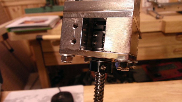
@Bob: Very special thanks on the new z-axis thrust bearing design you shared. That seems to work great and attached are pictures on what that came out to with the part numbers of the INA bearings and washers I ended up using.
Here are some pictures of what went on so far, enjoy... :-)
--
Mac
2013-05-02 19_07_41-MomusX2.skp - SketchUp by mkloberg, on Flickr
0005-Base by mkloberg, on Flickr
0006-Closeup by mkloberg, on Flickr
0003-InitialRender by mkloberg, on Flickr
2013-03-17 22_25_44-MomusX2.skp - SketchUp by mkloberg, on Flickr
WP_20130306_001 by mkloberg, on Flickr
WP_20130412_007 by mkloberg, on Flickr
WP_20130412_015 by mkloberg, on Flickr
WP_20130418_002 by mkloberg, on Flickr
WP_20130418_004 by mkloberg, on Flickr
WP_20130418_007 by mkloberg, on Flickr
WP_20130429_009 by mkloberg, on Flickr
Thread: Build thread: Mac's Momus X2S
Results 1 to 20 of 166
-
05-03-2013, 04:02 AM #1
 Registered
- Join Date
- Mar 2013
- Posts
- 209
Build thread: Mac's Momus X2S
-
05-05-2013, 05:08 PM #2
Registered
- Join Date
- Apr 2010
- Posts
- 60
This is beautiful! I'm very much looking forward to your build progression. I also admire your level of skill with sketchup! Did you hand-cut all the aluminum? I see a dog bone on some of the plate inside corners which to me screams CNC cut, or a person who understands corner stresses
 .
.
Keep posting pictures, both of the metal and wood work, its looking great.
-
05-08-2013, 02:10 AM #3
Registered
- Join Date
- Mar 2013
- Posts
- 209
Thanks again, for the kind words. :-)
To answer your question: No, there was no CNC involved in mfg'ing the parts - everything so far I made in my one-car garage shop(!) which is also home to our washing machine and the dryer,lol. The drill press sits on top of the washing machine and I'm practically screaming for more space every day, but money is always tight...
Perhaps I can make a large number of garden gnomes on the Momus to pay for a bigger shop, hehe. I'm aready trying to train my GF in 3D design for making cool models to run on the machine. Design is already her daily job, but in the 2D world (Illustrator).
Anyways, I've got some serious catching up to do with this build thread because I waited too long to start it, I guess.
I'm already several weeks into the build and what you see above are only the highlights. Inspired by awesome detail in the threads of previous builders, I will try to do the same.
I've kind of grouped the pictures together by topic and will post them up until the thread is up to present time, then I will post more as progress is made.
Enjoy :-)
Mac
-
05-08-2013, 03:20 AM #4
Registered
- Join Date
- Mar 2013
- Posts
- 209
So I started the build several weeks ago, here is some more detail, trying to get the thread up to current events :-)
For my background, I've been woodworking for several years now but haven't done anyting this extensive with metal in general lately, so all this was somewhat new to me too. Bob's manual helped there a lot, some of his methods and tips on how to work with aluminum are pure gold.
I've had some experience with aluminum over the years and have gone through an extensive apprenticeship in metalworking about 25 years ago in Germany, so some of the techniques and processes I still remembered from way back then.
The very first thing I did was to make a holder for the various taps and drill bits used in this project, very handy and helps keep things tidy (helps with picking the wrong drill for the wrong hole too). I've done that a lot with other woodworking projects too, so that was a natural thing to start with for me.
It's just a piece of Cherry scrap wood I had laying around in the shop:

WP_20130307_002 by mkloberg, on Flickr
Most of these are Dewalt pilot point drills available as a set at your local hardware store, I can highly recommend these.
They don't wear out all that quick in aluminum and track very good because of the pilot point.
This is my marking setup, I had everying before starting the project, except for the granite stone.
I got that thing off e-bay for relatively cheap before starting because I remembered how important the stone is for marking from my apprenticeship.
This will also help with aligning the carriage square, because the stone is guaranteed to be dead flat.

WP_20130306_004 by mkloberg, on Flickr
All the aluminum cutting was done with a cheapo Chinese 10' miter saw from Harbor Freight (about $100 after 20% off coupon ;-).
The other option would have been to try to cut it on this old 20 inch Rockwell Bandsaw here, but that thing is alreay 60 years old and I'm a bit worried about getting aluminum chips into its tires... I resaw veneer on this thing, so that might screw things up later on ;-)
Back to the the miter saw, I've used this thing for a few years now with wood only and it has its special issues (wobbly shaft, poor dust collection, etc). Turns out that it was just poorly adjusted and after putting a high quality aluminum targeted blade (Oshlun, $45 on Amazon Prime) into this crappy saw, it turned out some high quality, and repetable cuts. I also used the Olson wax stick heavily, as Bob recommended in the manual.

WP_20130507_002 by mkloberg, on Flickr

WP_20130306_008 by mkloberg, on Flickr

WP_20130306_009 by mkloberg, on Flickr
That sheet of MDF to the right of the saw is to shield the rest of the shop from the flying aluminum chips by the way, holy crap - that stuff flies everywhere. You probably won't believe this, but I've seen tiny aluminum particles hover in the air actually. Strange... Almost as bad as the dust from cutting MDF in a way. Makes you want to put on a dust mask while cutting this stuff. While cutting the pieces I also got into trouble with my GF, because that stuff stuck to my shoes and got tracked all over the house.
She made me wear two pairs of shoes, one pair for the shop and one pair for the house changing them at the door to the shop. That worked out pretty good, still kinda funny... :-)
-
05-08-2013, 03:46 AM #5
Registered
- Join Date
- Mar 2013
- Posts
- 209
The method I used to cut the Aluminum involved only the cheapo miter saw and a Porter Cable sanding station I've had in the shop all along.
For the cuts, I applied plenty of the wax stick to the blade and made sure the shop vac was going to suck most of the aluminum chips out of the saw, more or less like damage control because the stuff was flying everywhere to begin with.
Alignment of the parts in the saw was fairly easy, I just picked a tooth that cuts on the right side of the blade and shifted the blade as close up to the scribed line as possible.
That took a little practice at first, but soon I got the hang of it and got darn close to the target dimension down the road.
The blade still seemed to wobble a bit, so I marked one of the right side teeth black that seemed to be on the top of the wobble with permanent marker and I ended up doing all the cutting alignment with that one "Black Tooth", lol.

WP_20130307_005 by mkloberg, on Flickr
I found that most of the time using this techinique, the cut was extremely close to the target dimension.

WP_20130308_001 by mkloberg, on Flickr
-
05-08-2013, 04:05 AM #6
Registered
- Join Date
- Mar 2013
- Posts
- 209
To square the ends of the cut pieces, I was thinking about filing them by hand but the sheer number of these areas made me think of a different method.
I have a Porter Cable sanding station that I use all the time for woodworking, so I tried to put a 8" 80 grid sanding disk in there, running some aluminum scraps against it.
That worked out really well, with nearly no wear on the disk, just a lot of heat building up on the work piece, this gets really hot in no time.
Nevertheless, I finished all pieces that way with very good results. I found out that one pass on the disk with light pressure equates to removal of material of about 2 thousands of an inch.
Knowing this, I was able to make the parts almost dead nuts in terms of lenght and perfectly square after fiddling around with the angle of the support plate on the grinder to get that square to the disk. The stupid thing is that you have to take off the support plate to change worn out disks and realign everything again. I went through 3 80 grid disks in this project.

WP_20130324_005 by mkloberg, on Flickr
While grinding carefully, I always kept an eye on the squareness of the part.
Sometimes that would reqire ajustments on the grinder, etc.:

WP_20130324_006 by mkloberg, on Flickr
On a few occations, my fingers got so hot that it hurt using this method, lol.
The results were very good though, on some of the parts - hit or miss, I hit the target dimension to the last digit :
:

WP_20130324_004 by mkloberg, on Flickr
-
05-08-2013, 04:37 AM #7
Registered
- Join Date
- Mar 2013
- Posts
- 209
At some point I was confronted with cuttting the main Z-Axis plate (mod).
I got a little bit scared at first of making this part and thought a few times of contracting this out to a local machine shop, but then I tried it anways.
The problem was that the dimensions of the plate are in a way that you can't clamp this or cut it on the miter saw. The only other option would have been by hand, with a hacksaw, but I didn't feel like that. Then I thought about my trusty Bosh Jig-Saw: Just clamping the stock on the corner of the desk and having at it, worked out great, at first I thought it would not, I've never used this saw on metal before, but it did make a really nice cut, using a standard metal blade that comes with the saw.
Amazing .... :-)

WP_20130330_003 by mkloberg, on Flickr

WP_20130330_005 by mkloberg, on Flickr
-
05-08-2013, 05:07 AM #8
Registered
- Join Date
- Mar 2013
- Posts
- 209
At that point, most of the major aluminum parts were cut an marked, ready for drilling:

WP_20130330_002 by mkloberg, on Flickr
Half way through the centering drilling process, I noticed that my old trusty benchtop drill press was a little bit too weak for this project.

WP_20130306_006 by mkloberg, on Flickr
I've done everything in woodworking for the past few years on this thing without noticing a problem, but now two different problems surfaced: For metal, the runout on this press is too much, making the workpiece trying to wobble inside the vise. What made it worse was that the flimsy table would give away and actually bend down when trying to drill into the Momus parts.
Long story short, I had to find a sturdier drill press (to go on top of the washing machine ;-).
After some running around, I found a floor model from our local Sears store and they were willing to let it go for $120. After that I sold my old one for $50 on Craigslist, it took two weeks but someone showed up finally and took it. That was a nice upgrade for little extra money.
I had to shorten the column of the new drill press to make it fit in the shop, under the cabinets, but that's another story.

WP_20130325_003 by mkloberg, on Flickr
Checking alignment and runout of the new drill-press:

WP_20130325_005 by mkloberg, on Flickr

WP_20130325_007 by mkloberg, on Flickr
-
05-08-2013, 01:02 PM #9
Registered

- Join Date
- Aug 2006
- Posts
- 132
Your innovation and adaptation is remarkable!
Build and modify on!
-=Doug"IT ≠ IQ " Starwalt 1999
-
05-09-2013, 02:59 AM #10
Registered
- Join Date
- Mar 2013
- Posts
- 209
Thanks Doug :-)
All the holes were center punched at this point, so I drilled pilot holes using a small center hole drill into all parts.
The part with the dogbone that Freerider mentioned earlier is the lower Z-axis thrust bearing support plate.

WP_20130407_001 by mkloberg, on Flickr
I was taught it helps to spin the center hole drill backwards a little by hand by applying light pressure to give the part an inital location.

WP_20130309_004 by mkloberg, on Flickr
Then the drilling and tapping started, that took me a few evenings. For a drilling and tapping lubricant, I used Tap-Magic for Aluminum and that very liberally. It's great stuff.

WP_20130313_011 by mkloberg, on Flickr
Some parts can be drilled clamped together in the vise.

WP_20130401_002 by mkloberg, on Flickr
Making the y-axis motor mounts with a hole saw. Tip here: DO take Bobs advice from the manual, and drill the chip clearing holes first - I forgot about that and the hole saw got clogged with chips all the time.

WP_20130404_002 by mkloberg, on Flickr
You can see the marred surface of the cut because of that oversight, so I had to clean that up with a file afterwards.

WP_20130404_003 by mkloberg, on Flickr
Part 13 was fun to make too, but fortunately Bob provides an alternate design for this in plan you can choose to cut the clearance corners or not.
I went for it and that went reasonably well with a hacksaw, file and some elbow grease.

WP_20130405_004 by mkloberg, on Flickr

WP_20130405_005 by mkloberg, on Flickr
Note that there are two strips or cork glued on the vise jaws. This helps a lot with preventing surface damage to the aluminum parts.
You can get self adhesive cork on rolls in the hardware store. Usually it's used to line kitchen drawers.

WP_20130406_001 by mkloberg, on Flickr
-
05-09-2013, 11:15 AM #11
Registered
- Join Date
- Mar 2013
- Posts
- 209
Then I countersunk and c-bored the neccessary holes so all holes were ready for tapping now.
I remembered a handy little tool called a tap-guide (few dollars on Amazon).
It's basically a little cylinder with a spring loaded pin that is held in your drill press chuck.
The pointy end of the pin fits into a divit on top of your tap handle.
To use it, you set up the part to tap in the dril press, align the pointy end over hole and just lower the table to a point where the tap with the handle fits between the hole and the pin.
Then applying light pressure with the drill press chuck so that the spring is loaded, start tapping.
That, and a spritz of the tap-magic fluid made tapping the holes really painless, so I thought I'd share this little trick with those that are not aware of this handy little helper tool. :-)

WP_20130318_001 by mkloberg, on Flickr
After the tapping was done, I cut, drilled and filed the openings on the gantry tube.
I used the same sanding process as shown earlier to square up the ends.
That took a while, because of the odd shape of the tube, but I got pretty close on that as well :-)

WP_20130409_006 by mkloberg, on Flickr
Then I went ahead and brushed, buffed and polished the parts because I figured that would take ony a few minutes per part.
For brushing, I used these sanding sponges you can get at the hardware store for cheap (150/220 grid, doesn't matter all that much).

WP_20130507_003 by mkloberg, on Flickr
Since the parts still had tap-magic all over it, that make for a neat wet sanding process.
You may want to wear some latex finishing gloves for that, the buffing and polishing, that got kind of messy.
For buffing, I used a felt wheel on my bench grinder with green buffing compound.
For cleaning and polishing, I used regular kitchen towels, white shop rags and a product called 882 Liquid Metal Polish from Duragloss.

WP_20130411_001 by mkloberg, on Flickr
I suppose any chrome/metal type automtive polishing product might do, but this stuff really made the parts shine almost like chrome (available from Northern Tool).
Meanwhile the motors, the belt, the thrust bearings and some other odds and ends arrived at the shop.

WP_20130407_003 by mkloberg, on Flickr
Up to the next step, which was making the studs and cutting the z-axis screw.
I started to clean the stainless steel rods by holding them in a cordless drill running in reverse and wiping the dirt off with a rag and some goof-off.
That made them really shiny, cleared the threads of all debris that came with them and got all the shipping grease off.
I guess that seems like another "prettyfying" step, but I figured it's important and helps the thread locking compound to get a solid grip in the threads later on.

WP_20130407_005 by mkloberg, on Flickr
What a difference that made (top before, below after) :-)

WP_20130407_004 by mkloberg, on Flickr
For cutting and chamfering it was then off to the mini lathe.

WP_20130407_008 by mkloberg, on Flickr

WP_20130408_004 by mkloberg, on Flickr

WP_20130408_003 by mkloberg, on Flickr
Next up was cutting the z-axis screw, same process.

WP_20130418_001 by mkloberg, on Flickr
So far so good and pretty much ready for a dry run assembly.

WP_20130408_011 by mkloberg, on Flickr
-
05-09-2013, 12:19 PM #12
Registered
- Join Date
- Aug 2006
- Posts
- 132
Excellent documentation and I wondered how you got all your parts soooo pretty. Makes for nice 'curb appeal'.
A tap guide was employed in my build also. Actually I would drill the hole, change the tool to the tap guide, tap the hole, move to the next.
It was SLOW but it made sure I was tapping on the center I drilled.
+1 on the chip clearance holes for the Z motor support.
I left them ugly to remind me to do better next time.
-=Doug"IT ≠ IQ " Starwalt 1999
-
05-13-2013, 04:46 AM #13
Registered
- Join Date
- Mar 2013
- Posts
- 209
Thanks again Doug :-)
I'll document the final assembly later, as everything has to come apart again anyways for pinning and thread locking.
The past few days, I've made good progress on the bench for the big Momus to sit on.
These are the legs:

WP_20130428_001 by mkloberg, on Flickr
The levelers needed a ledge to hang on to, so I had to nibble those our with a chisel:

WP_20130427_001 by mkloberg, on Flickr
Assembly test and test glue up of one of the sides of the bench:

WP_20130428_008 by mkloberg, on Flickr
I had to wait for a while for that to dry, so I turned to the design of the hood for the machine.
Lots of compound angles, difficult to get a grip on... :-)

WP_20130430_002 by mkloberg, on Flickr
The wheels and levelers installed in place. We're going to to have to take them back off for the finish to be applied.

WP_20130504_003 by mkloberg, on Flickr
Gluing the ribs for the front face into place (this will be the clamping surface for anything that goes up vertically into the machine).

WP_20130505_001 by mkloberg, on Flickr
Tank asseblies, these are the two sides to the bench, rock solid:

WP_20130506_002 by mkloberg, on Flickr
A good sanding and general application with boiled Linseed Oil finished this part of the job.

WP_20130511_005 by mkloberg, on Flickr
This is the completed table, to suppport the upcoming Momus.
The finish is very simple, just boiled Linseed Oil, commonly found in work benches.
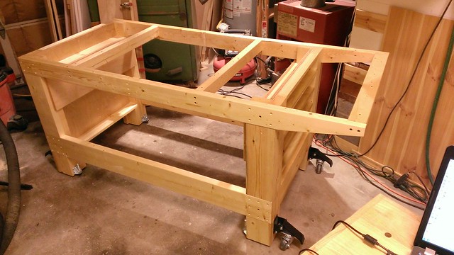
WP_20130511_008 by mkloberg, on Flickr
Design for the base:

WP_20130512_003.1 by mkloberg, on Flickr
Cutting the ribs for the torsion frame:

WP_20130512_001 by mkloberg, on Flickr
Trying to figure out the the layout for the ribs (to make it repeatable for the other parts:

WP_20130512_004 by mkloberg, on Flickr
-
05-25-2013, 01:19 PM #14
Registered
- Join Date
- Mar 2013
- Posts
- 209
Yesterday, I ordered the motor cables, the GeckoDrive G540, a SmoothStepper board and the limit switches.
I heard that there are different revisions of the Gecko floating around at the different distributors.
Probably not a big deal, but I wanted to have the latest revision with the latest upgrades and fixes, which I heard is REV-8, so I decided to order the board directly from Gecko.
The other stuff I ordered from CncRouterParts.
I planned to run this machine from the beginning over Ethernet, because putting a dedicated PC under the machine was calling for trouble in my mind.
I'm just afraid that the wood dust will make its way onto the motherboard, giving it a live span of about a year before it will die (been there done that).
I know that better dust collection might be the solution to that, but I just haven't had the space in my little garage to implement a decent cyclone dust collection system yet.
That dust is not neccessarily coming from the Momus, but from all the other stuff I do in the shop.
THe shopvac will have to do for another while. That's just the situation I'm in right now.
So, I ordered a Smoothstepper Ethernet board to get around that whole issue and will run it off a laptop over Ethernet.
Should be interesting how that plays out :-)
This week I spent on building up the torsion box for the machine.
The first ribs for it I made from scraps I had laying around in the shop.
The bottom and top skin for the machine base called for full sheets of plywood, so I had to cut these outside with the circular saw.

WP_20130510_004 by mkloberg, on Flickr
Cutting the strips for the ribs on the table saw, it has a custom fence for jointing (that's another story ;-)

WP_20130522_017 by mkloberg, on Flickr
I'm taking the measurements right out of the model this time, I used to try to print these out before cutting, but this works too.

WP_20130523_014 by mkloberg, on Flickr
I made one "master" rib to see where the holes and notches need to be and marked that all up.

WP_20130512_004 by mkloberg, on Flickr
Considereing how often that pattern needed to be repeated, I made a template out of acrylic glass that has all the marks and locations of the holes and notches in it.
I then used that template to punch through and mark the locations of the holes in all the other parts.

WP_20130513_001 by mkloberg, on Flickr
There are a lot of holes to drill. I failed the hole-saw game when trying to make the motor mount, so I made sure I'll do it this time (that is, drilling the clearance holes for the chips to fall out).
So I did, resulting in this pattern:

WP_20130514_003 by mkloberg, on Flickr
That worked out pretty good, easy to do. Just drill two extra holes per opening for the chips to fall out the bottom.
Somewhere around this this step, I did some more research around drilling speeds and found out that low and behold!!! - a hole saw at this size is supposed to run at 2400 rpm in wood.
Bummer. I was trying to run it as slow as possible (around 600 rpm), so I learned something new.
Seriously, running at that higher speed really helped the chips to fall out (because the chips are shorter in size) and clogs less.
For me that was kind of a revelation on its own and I will keep that in mind once it comes to running things in the CNC world (chip length is of great importance).

WP_20130513_005 by mkloberg, on Flickr

WP_20130513_008 by mkloberg, on Flickr
Some of the ribs on the base, the hole drilling process works, without leaving burn marks on the holes.

WP_20130514_005 by mkloberg, on Flickr
Next up was cutting the notches (1.25 x 3/4) into the torsion box members.
The problem I had with that was that I have a perfectly good table saw sled to do things like that.

WP_20130522_018 by mkloberg, on Flickr
On my saw, with a 10" dado set, I could not get the blade high enough to do the cut on my regular sled.
In the end I decided to build a new table saw sled for this purpose.

WP_20130516_002 by mkloberg, on Flickr
Fitting the runners and the top sled plate into the saw:

WP_20130517_003 by mkloberg, on Flickr
The finished sled. Notice that it has a very long arm, with an adjustable stop - this will really help getting the notches in the frame to cut where they need to be.

WP_20130521_007 by mkloberg, on Flickr
Very first test cut.

WP_20130521_011 by mkloberg, on Flickr
Cutting the y-axis ribs. Note how the end of the rib rests against the stop. This is going to make them all the same, precisely.

WP_20130521_012 by mkloberg, on Flickr
Pretty close :-)

WP_20130522_019 by mkloberg, on Flickr
Cutting the long ribs, very same process, just longer.

WP_20130523_008 by mkloberg, on Flickr
That was a lot of holes to hole-saw ;-) Now I really know how this works, chip clearance holes really are the ticket!

WP_20130524_005 by mkloberg, on Flickr
All parts are ready for the torsion box to come together, yay!

WP_20130524_008 by mkloberg, on Flickr
-
05-25-2013, 02:48 PM #15
Registered
- Join Date
- Aug 2006
- Posts
- 132
This is reason I enjoy this past time, clever people doing beautiful, clever work.
Thank you Mac.CNC!
-=Doug"IT ≠ IQ " Starwalt 1999
-
05-30-2013, 05:49 AM #16
Registered
- Join Date
- Mar 2013
- Posts
- 209
This week I worked some more on the momus. With all the ribs cut, I tried a dry assembly of the torsion box:

WP_20130525_002 by mkloberg, on Flickr
That came out pretty good.
After some thinking, considering the size of that whole thing I figured that that it might be best to assemble the top skin to the torsion box upside down, so what you are going to see from here might be a little confusing.

WP_20130528_005 by mkloberg, on Flickr
Peeping Tom, just making sure it's still all in a line.

WP_20130525_004 by mkloberg, on Flickr
Drilling the through rib holes that fasten the ribs to the top skin. I counted about 150 holes, countersunk.

WP_20130525_007 by mkloberg, on Flickr
All done, so I thought :-)

WP_20130527_002 by mkloberg, on Flickr
I forgort about the special feature opening in the top and the bottom skin for the vertical routing.

WP_20130525_003 by mkloberg, on Flickr
No big deal, we'll just jig-saw that out.

WP_20130526_005 by mkloberg, on Flickr
Using some of the left over aluminum bars as guides and a carpenters square, this was pretty easy.

WP_20130526_007 by mkloberg, on Flickr
What wasn't so easy was how to cut the front and the back of the machine as these are pretty odd shapes. Probabably my fault too. Anyways, here we go:

WP_20130527_007 by mkloberg, on Flickr
I forgot that there need to be cable/clearance holes in the top skin, those need to be cut too:

WP_20130528_001 by mkloberg, on Flickr
Trust me, you don't want to operate a 1.5" hole-saw in a hand drill. THat's not funny... (but it works, if you really have to)
Notches and holes cut, it's finally time to glue to the torsion box ribs to the top skin.
I've been thinking about this for a while and my take on this is that it's best to tighten it all up with long screws that come up from the bottom, throught the frame.
Next the bottom skin reinforces it all with short screwsm driven in at strategic locations, something like that.
The glue to make that all happen is of great importance in my mind. Using a regular wood glue would result in an uneven CNC base surface, because it will settle and harden before the entire rib structure could be fastened down to the top skin (upside down).
Luckily, there is the "Liquid Hide Wood Glue", which I've used in the past for cabinet work. The idea with this glue is that this is a very slow setting glue, you have about an hour to move things around until this glue sets.

WP_20130529_005 by mkloberg, on Flickr
This worked out pretty good and I got a nice and even distribution of glue flowing out of where it needed to be, while driving about 150 screws into the ribs, in a hurry , to fasten them to the skin in a hurry.

WP_20130529_006 by mkloberg, on Flickr
Glue came out everywhere, I didn't expect the down pressure to be this high.

WP_20130529_007 by mkloberg, on Flickr
Yesterday, I was thinking about how to light up the machine. I remember that Bob had some light bars in the over of the machine... Just shopping around.
I found a cheap solution on amazon, involving lights that are normally installed under stairs. They seem like they won't heat up the machine all that much, are
easy to install, etc. Looks like there is going to be 12 of these lights built inside the machine to illuminate the workspace.

WP_20130529_010 by mkloberg, on Flickr
Some other parts arrived today too :-)

WP_20130529_017 by mkloberg, on Flickr
-
05-30-2013, 12:18 PM #17
Registered
- Join Date
- Aug 2006
- Posts
- 132
Nice documentation!
Those lights look nifty. I too have been wondering about internal lighting...while I sand, fill, sand, fill.
If I build another one of these things, I will be using a totally different cabinet grade wood. My earlier complaints about the material are still valid.
I should have gone with the 'blondewood' option at my local Lowe's.
Your build is looking super.
-=Doug"IT ≠ IQ " Starwalt 1999
-
05-31-2013, 05:02 AM #18
Registered
- Join Date
- Mar 2013
- Posts
- 209
Thanks again, Doug :-)
The thickness and quality of the plywood bothers me too, a whole lot. That most
common plywood is not actually 3/4 in thickness I knew before, but what effect
that had in terms of my sketchup model and how to build it, caught me off guard
a couple of days ago. There are ways to compensate for that issue, so I did, but
the quality of the stuff I bought wasn't that great either.
What happened here was that I drove all the way to Norfolk in the hope to pick
up some really good cabinet grade maple plywood. When I picked it up, it looked
good (stacked) and there were no visible voids on the outside of the sheets.
When I unloaded them, on two of these sheets, the top layer was completely
seperated and had peeled back in the corner to about 2 feet. I payed $65 per
sheet, expecting that to be top quality stuff, but it wasn't. :-( I won't name
the distributor, I'm sure it wasn't their fault - and I'm too lazy to load it
all up again, drive all the way back there to get these replaced.
Dang. Dang, Dang, I'll have and just will cut around those defects.
So I'm with you, what is left after going through the four expensive sheets
(I'll probably need two more), the rest will come from Lowes (~$45 last time I
looked).
In other news, today was all about getting the bottom skin ready, to be joined
with the torsion box.
There was a slight problem with one of the vertical ribs not having settled down
properly onto to the top skin, so I sanded that problem away, to make the bottom
skin sit flat on the torsion box.

WP_20130530_002 by mkloberg, on Flickr
The front and back plates need to sit between the top and the bottom skin, so I
was little bit worried that once these two are in their permanent places, it
would be hard to get the front and back plates inbetween there. Long story
short, these need to be part of that assembly process or there is going to be
trouble.
The front and back plates are going to have fans in them, to cool the
electronics inside the sides of the Momus. Most of that stuff is going to be
inside the left wall of the Machine. That's just because of the way it will sit in
the garage, but who knows, perhaps there will be some other stuff in the right
side of the machine in the future. I'm a symetrical guy, so who knows, lol.
Point is that we'll just cut it all the same, and keep it symetrical.
There is going to be at least 6 PC-type 60mm fans, 3 in the front - to suck, 3
in the back, to exhaust on each side. In the front, I plan to install some sort of filter
fabric to keep the wood dust to get into the cavity where the electronics
components are (that being the left wall). I ordered the fans a couple of days
ago, but they didn't make it here yet, so I had to improvise without having the fans here.
Big holes, through the front and the back of the end plates:

WP_20130530_001 by mkloberg, on Flickr

WP_20130530_004 by mkloberg, on Flickr
Dry assembly of the finished back plate:

WP_20130530_006 by mkloberg, on Flickr
The Gecko-Drive made it to the shop today too, the heart of this machine:

WP_20130530_005 by mkloberg, on Flickr
-
06-12-2013, 04:30 AM #19
Registered
- Join Date
- Mar 2013
- Posts
- 209
Hello again, progress in the wood department was pretty good so far.
I've also found a possible supplier for the precision ground rails and ordered some more lights, more on that later.
Next up was fastening the bottom to the torsion box.
Since I didn't want any fasteners visible in the top, I've fastened the top through the ribs and had the screws pull the top into the ribs from underneath.
For the bottom, that meant that the screws had to come in through the bottom plate, since that's underneath they won't be visible, so I won't be even concerned about filling these.

WP_20130601_002 by mkloberg, on Flickr
A LOT of holes again, to drill and counter sink - this is basically the underside of the machine.

WP_20130601_001 by mkloberg, on Flickr
Getting ready to glue the bottom plate to the torsion box.
Here again, I used liquid hide glue - this stuff has the awesome property to settle very slow, that gave me about an hour to drive all the screws into the bottom before it would harden, making sure I'll end up with an even surface, even for the bottom.

WP_20130601_003 by mkloberg, on Flickr
At this point the bottom sort of "floats" on the rest of the frame, due to the glue (until it hardens that is).
Because of the special glue, it was really easy to make adjustments and nudge the big bottom plate into the correct location to align properly with the rest of the assembly.

WP_20130601_006 by mkloberg, on Flickr
In the right place now, time to drive in a 'few' ;-) screws to fasten it down.

WP_20130601_007 by mkloberg, on Flickr
I actually let the assembly sit there for a day to make sure the slow setting glue dried undisturbed.
Then I flipped it over and started cutting the members for the side walls.

WP_20130602_001 by mkloberg, on Flickr
Over the years working with wood, I've learned that the method to get a really tight fit = forget about the plans.
You can pretty much consider wood a living and breathing "thing", I'd almost say organism, it expands and contracts depending on humidity in whatever environment it is located in.
It can be a lot or very little, depending on the environment and the spcies of wood.
This behavior is of course not very evident in plywood, but that's just how I "think" when building something.
Fitting the long side ribs into the standing assembly, for a zero clearance fit.
The top board needs another 32nd shaved off its end, because it bows up sitting inbetween.

WP_20130602_004 by mkloberg, on Flickr
I figured it might be a good idea to keep the left bay well ventilated because of all the electronics that need to go in there, so there's going to be some PC type fans moving air in the front and the back of the machine.
That called for some pretty big holes in the front and back plates in this assembly.

WP_20130603_006 by mkloberg, on Flickr
I'm not sure who designed these fans, but it turned out that the blades would touch the surface of the mounting plates and stall, so I had to route a 1/4 inner round into each opening to let the fan blades spin freely.

WP_20130603_017 by mkloberg, on Flickr

WP_20130604_003 by mkloberg, on Flickr
All side wall members cut and drilled for assembly

WP_20130607_002 by mkloberg, on Flickr
The sidewall assembly process had me intrigued for a while, there are many options on how to do this (somewhere else), but in the end the presumably flat surface of the machine itself won.
Another benefit of doing it that way is the constraint between the front and the back plates to keep the assembly aligned.

WP_20130608_001 by mkloberg, on Flickr
That worked out pretty good. It's pretty BIG!
Seriously, working with it for a long time now in Sketchup gave me no concept on how big this thing really is. I was a bit wow'ed to say the least at this point.

WP_20130608_006 by mkloberg, on Flickr
Next up was routing the maintenance pockets for the lower bearings into both of the side walls. I did that in three depth passes and it turned out pretty good.
Having solid straight edges available is defenitely an advantage here.

WP_20130609_005 by mkloberg, on Flickr

WP_20130609_004 by mkloberg, on Flickr
So far so good.

WP_20130609_008 by mkloberg, on Flickr
Then I focused on the fastening holes to join the two inner side plates to the side ribs.
The only other holes that needed to go into the side walls would be 1" holes to provide for the lights to illuminate the work area.
Ballancing a workpiece that large on a drill press for hole sawing something was something else.

WP_20130610_002 by mkloberg, on Flickr
Trying out the first set of 6 lights

WP_20130610_005 by mkloberg, on Flickr

WP_20130610_008 by mkloberg, on Flickr
Unfortunately, the lights that I got off Amazon didn't provide enough Lumens to effectively light up the work area, so I decided to double it up.
Now there's going to be 24 of these, 12 on each side, leading to more 1" holes to be drilled into the side walls.

WP_20130611_012 by mkloberg, on Flickr
Drilling holes on the other side wall

WP_20130611_011 by mkloberg, on Flickr
Looks just like the model now, yay! This is all dry assembly for now, tomorrow I'll try to glue and screw the side walls in place, after hopefully solving this little problem:

WP_20130611_014 by mkloberg, on Flickr
For some reason, I have a about 1mm gap in the font of the torsion box that goes down about a foot. I'm not sure yet where that came from, but I'd like to keep that in check and understand that better.

WP_20130611_016 by mkloberg, on Flickr
It probably won't make a difference once the epoxy gets poured into the working bed, but I'm a little concerned that this will transfer to the top of the machine into the rail mounting surfaces once I tighten down the side walls to the bed.
I even thought about filling that gap up with glue, letting it settle and tighten it down later, etc... I'm just not sure where that came from and what to do about it.
For now, I propped up the front of the machine by 1/4 with a spacer (it's HEAVY), to see if might settle by itself in a few days.
:-)
-
06-17-2013, 08:42 PM #20
Registered
- Join Date
- Aug 2006
- Posts
- 132
I had the same kind of gaps as I assembled my base. As you said, this stuff lives and breaths.
My approach was to fill it and sand it. Speaking of filling and sanding, I am still doing that...ugh.
Neat idea with the lights. I will stay with the original plan of cover mounted lights but there will be some shadows.
Your idea will probably negate most shadows. It is easy to add at that stage of the game.
Work tied me up 14 days straight and I am going into Momus withdrawals. I am off this week and hope to get more done.
-=Doug"IT ≠ IQ " Starwalt 1999


 Reply With Quote
Similar Threads
-
New Momus Build
By Jkountz in forum Momus Design CNC plansReplies: 80Last Post: 04-04-2014, 11:24 AM -
404's Momus V2.0 build
By e404_forbidden in forum Momus Design CNC plansReplies: 13Last Post: 09-22-2013, 02:49 PM -
Sven's modified Momus build thread
By svenw in forum Momus Design CNC plansReplies: 7Last Post: 11-27-2012, 06:24 AM -
Rob's Momus Build
By rwhittle in forum Momus Design CNC plansReplies: 8Last Post: 04-08-2012, 08:41 PM -
My Momus build
By TeslaFreakshow in forum Momus Design CNC plansReplies: 29Last Post: 12-06-2011, 11:35 PM
