


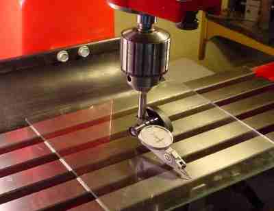
After noticing that parts keep coming out with measurable tilt in the Y axis and X/Y position drift during Z movement I thought I should go ahead and start trying to align the spindle. I had some drill rod cut to 6"-12"-14" and I am using that in a collet to indicate against.
It's become a disaster, quickly. If I average the runout of the drill rod at the top near the spindle and set that to 0 on the dial I get jacked up indications as I run the head up and down the column. I move a few inches and the next average tells me I'm 0.0005" high. Then a few inches later the average says I'm 0.002" low. Sometimes suddenly the average is nearly back on zero again. WTF????
Even if the drill rod is not square, (and of course it ain't) the average position should be reasonably consistent. To top it off the Y error I'm trying to fix seems to have the spindle axis kicked out away from the column which means I have to shim the top which has proved to be a royal pain in the kiester.
So is there some other method to attack this? I've burned a whole night here and the end result is a torn apart mill that is no doubt worse than it was.
Results 1 to 20 of 21
-
02-16-2010, 06:12 AM #1
 Registered
- Join Date
- Dec 2009
- Posts
- 1416
X2 spindle alignment (about to stomp puppies)
-
02-16-2010, 08:48 AM #2
Registered
- Join Date
- Dec 2008
- Posts
- 226
Is the column/z linear perpendicular to the x-y axis ???
mount your indicator on the z slide and indicate against a 123 block fastened to the table.
Then check the tram on your spindle by mouthing your indicator off center in the spindle, clamp an arm onto the drill rod and the indicator to this arm for example. and sweeping side to side on the table(rotating the spindle to measure in plus and minus directions)
I'm guessing your column needs to tilt forwards a touch... just a guess.
-
02-16-2010, 03:33 PM #3
Registered
- Join Date
- Dec 2009
- Posts
- 1416
Actually the column is off the mill. You have to remove and replace the head with each adjustment and I don't want to event attempt that with the mill head loose on the dovetails and vertical.
After some cool-down time I think I might order some precision rod. I think the OD of the drill rod is fluctuating and that is what's causing the tilt I come up with to change so much over the course of the rod. If it were just run-out then my error indicated between run-out maximums should always be increasing in one direction. That's whats killing me.
I got the 6" piece to indicate less than 0.0005" over 4.5" of travel. It also indicated a smaller error at the mid-point that was in the same direction but at this point I want certainty before I put this thing back together again and have to then tram it to the table. I'll bet good money that If I use a different rod then I'll get a different answer.
With the way these things are put together I have no doubt that I will also have to shim the column somehow to correct any forward/backward lean it has.
-
02-16-2010, 06:47 PM #4
Gold Member
- Join Date
- Jun 2006
- Posts
- 2512
Using a rod is completely the wrong way to go about things, even precision rod.
There are many issues that will result in the spindle axis not being at 90 degrees to the table travel. The normal is that some or all of these issues contribute to the problem. If you do not follow the correct procedure you will measure the result of a number of these issues then try to correct it by adjusting only one. This puts you deeper into the long grass. Which is where you currently find yourself.
The two basic conditions are:
The column vee ways need to be perpendicular to the table travel in both planes.
The spindle axis needs to be parallel to the column ways in both planes.
Add to this the possibility of loose gibs and twist or bent column and/or table, plus table surface not parallel to table ways, and spindle not parallel to head ways and you have a large tangle of possible sources of error that you need to untangle. Somebody will probably list some more.
The correct process is to check and correct each and every condition in the right sequence as you assemble the machine. However as you probably don't have the capability or the equipment to correct bent or twisted components, or surfaces that have not been ground parallel to each other it is an acceptable compromise to take short cuts, with or course the attendent loss of precision.
The shot cut method is in 2 steps as follows:
1) Use an angle plate (or similar) on the table with a DTI on the head (not in the spindle) to check that the column ways are perpendicular to the table surface, by moving the head up and down (with gibs tight). Rotate the angle plate 90 degrees and repeat in order to eliminate any angle plate errors. Use shims under the column to adjust.
2) Sweep the table with a DTI mounted in the spindle and adjust the head to correct any errors. This correction has varying degrees of difficulty depending on your machine/head design.
Do the tests/adjustments in the sequence listed and within the envelope that you use most, because you will not be able to correct for bent/twisted components etc, so it's a compromise.
If you complete this and are still not happy, put your machine on eBay and start looking for a better built machine. It will be cheaper and save you hundreds of frustrating manhours.
Phil
 Originally Posted by photomankc

-
02-16-2010, 09:11 PM #5
Registered
- Join Date
- Dec 2009
- Posts
- 1416
I'm certainly not closed to ideas, this is not going well obviously, but I don't see how I can possibly test movement against the table when the spindle is not parallel to the X/Z and Y/Z axises. That is where I am. I can tram the X in well without taking the head off but that will result in movement in X position quickly as Z is moved up or down. Y can't be trammed at all without shimming something.
You can't adjust either of these without taking the head off of the column. There is no way I can see to reasonably do that with the tables attached and the column vertical so I can't use the tables to measure anything until this part is complete.
http://homemodelenginemachinist.com/...p?topic=6007.0
That's the procedure I'm using... what should I do different?
-
02-16-2010, 09:57 PM #6
Registered
- Join Date
- Dec 2008
- Posts
- 226
I realize now from your link that the bolts are hard to get at on the carriage, this will take some work but hopefully you only have to do it once....
This is basically what was said before, rephrased for clarity.
First off put the mill back together.
Next attach a 90 degree block of some sort, machinist square etc. to the table near your Z carriage.
This will be perpendicular to the table surface, and along the axis you are tramming.
Attach the indicator to the carriage, and indicate against the block, as you move the carriage up and down, it should move parallel to the block indicating "0" movement sideways/fore/aft
If it is not, shim the base of the column until the column is square with the table.
Next, tram the spindle to the table. First in the y axis....
here is an example of a sweep indicator setup...
Sweep for and aft then decide if the spindle needs to tilt ahead or back, you might want to do a little math to try and reduce the repetition, but remove the carriage and shim the top or bottom then resemble and check tram.
When the Y is trammed loosen the carriage bolts just enough to be able to rotate the spindle to tram along the x axis with light taps (use best judgment), not loose enough to lose the shims... same thing, sweep from left to right and nudge the spindle into tram.... Off once again and tighten the bolts.
Hopefully when tight nothing moved and your done... if not... readjust as necessary.
It may seem more difficult of a method, but no worries about bent drill stock and I dare say a more accurate final setup.
P.S. Either indicate against the table, or if using a plate to sweep on use something very flat and consistent thickness. Try putting some masking tape over the tooling groves in your table to sweep the indicator over.
Hope it goes quickly and the puppies are saved :P
-
02-16-2010, 10:25 PM #7
Registered
- Join Date
- Dec 2009
- Posts
- 1416
Ahhh hah. I see what you are saying now. Though I still think trying to lift that head on and off vertically trying shims will be.... unfun.
The precision rod was ordered last night and so it's already on it's way. I think I'll leave it torn down for now and see how far I get with that and follow up with what you suggest once the column is back on if I don't see the desired improvement. I'm just a little nervous to have that much weight hanging without support from the torsion spring while taking it on and off. To get it off and on the gib has to be really loose.
Thanks for the suggestion. It feels better to have a plan B rather than just looking at your mess and thinking "Well, *%@$".
-
02-16-2010, 10:36 PM #8
Registered
- Join Date
- Dec 2008
- Posts
- 226
Probably a bad idea, but how about taking the spindle off and using the bolt holes as guides to drill holes just big enough to put an alan key through the column ??? I wouldn't want you to ruin the ways though....
-
02-16-2010, 10:48 PM #9
Registered
- Join Date
- Dec 2009
- Posts
- 1416
I'd have to that by hand as the mill is the only piece of machine equipment I have in the house. It's been my drill-press too. Not sure how comfortable I'd be doing that with a DeWalt power drill. I did see a little part made to add adjustment bolts for the X alignment attached to the motor mount so that it's much less fiddly to get it lined up and then tightened down without it moving in the process. Definitely that will be high on my project list.
-
02-17-2010, 06:16 AM #10
Registered
- Join Date
- Dec 2009
- Posts
- 1416
Well, just had a "there's your problem" moment. Found a nice dent on the edge of the way on the Z column. As soon as the carriage hits that it lifts up by about 0.003" and holds pretty steady. After it rides up onto that it indicates less than 0.0005" over the next 3 inches of travel. So that explains the readings going all over the place from top to bottom. The carriage rides up over it at about 2.75" from the top and it appears it would remain there over the rest of the Z travel. I don't remember hitting anything over there but it's possible I guess. Crap.
So... time to make some plans. I see a couple options.
1.) See what I can do to remove the raised spot. I don't have much in the way of tools but it would seem to me that a small indention would be preferable to a proud mark so maybe just file out the bump as well as can be and live with it. If that's not possible then maybe I can see if just living with the loss of 2.5" of Z for best positional accuracy is workable. Except for drilling I wouldn't use that much but it would but a big damper on any plans to do turning work with the spindle that I had before.
2.) The option I'm leaning towards. Do nothing. Get it as straight as possible and use it for what I can get by with it for. Wait till the G0704 is shipping, get one. Take this one back to HF on my replacement plan and get a new one. Sell brand new one on Ebay and use proceeds against the G0704.
I'm strongly leaning towards two. The 0704 was not out when I picked the X2 or I would have gone for it I think given the cost and overall features.
-
02-17-2010, 07:18 PM #11
Registered
- Join Date
- Oct 2005
- Posts
- 1237
File it with a smooth mill file. This isn't rocket science.
-
02-17-2010, 07:44 PM #12
Registered
- Join Date
- Dec 2009
- Posts
- 1416
Didn't think it was rocket science but thought it was better to ask before filing on the ways.
-
02-17-2010, 08:30 PM #13
Registered

- Join Date
- Dec 2007
- Posts
- 362
I had a couple of similar dents on my mills dovetails.
Running a stone over them fixed the problem.Regards
Geoff
-
02-17-2010, 09:38 PM #14
Registered
- Join Date
- Oct 2005
- Posts
- 1237
Actually it is rocket science in some respects. Whenever something is new and we're unfamiliar, even the simplest things can appear daunting. I'm redoing parts of someone else's project and seeing that there are instances where a knowledgeable person might scratch their heads and ask why did a newbee do something a certain way? It (proper way) is only obvious when you know the right way. In your bump instance, filing or stoning the blemish is the right way.
-
02-17-2010, 10:40 PM #15
Registered
- Join Date
- Dec 2009
- Posts
- 1416
Cool. I actually have ordered the G0704 but I'll see if I can get that filed down to use it for some work till that gets here. I doubt the HF staff is going to inspect it that closely and the other problems I have are more bothersome anyway. My X table is concave at the edges with the worst of it being on the right side starting at the 1" mark. This explains the lift I was seeing trying to mount a Sherline rotary table over there. When the new one arrives I'll do the exchange and sell off the crated 44991 replacement.
-
02-19-2010, 07:33 AM #16
Registered
- Join Date
- Dec 2009
- Posts
- 1416
Ok the precision rod did help. It was much easier to see what was happening with the very smooth finish and straightness. I cant seem to work out the bump that seems to happen at the 2.5" mark. I just did what I could with the travel past that and if I calculated right got X/Y within .0015 over 7" of travel. That's good enough because I'm sick of taking the head on and off now.
Next I'll get a bit of plate glass and tram to the table. Looks like I will need to shim the column too since it leans a bit forward.
-
02-20-2010, 05:55 AM #17
Member
- Join Date
- May 2009
- Posts
- 141
You wouldn't really stomp on one of these would you???
This is our new pup lola.
Dale P.
-
02-20-2010, 06:48 AM #18
Registered
- Join Date
- Oct 2005
- Posts
- 1237
HO HO! Piddle puddle machine. Rotten time of year to house train a dog though. They get cold and want a warm place to pee. Will be hard to scold that cutie.
-
02-20-2010, 07:33 AM #19
Member
- Join Date
- May 2009
- Posts
- 141
Yes, I would have rather bought a puppy in the summer, but we lost all three or our dogs with in a 6 mo period due to age related issues and couldn't stand the quiet house. Thankfully we only have one room with carpet and the rest are all easy to clean surfaces. Not to mention the pup has been very good with the training and the messes have been very minimal. It still would have been nicer to have a puppy in the summer though.
Sorry for getting the post off topic!
Dale P.
-
02-21-2010, 02:36 AM #20
Registered
- Join Date
- Dec 2009
- Posts
- 1416
Got it back together today and trammed using the plate glass. Neat trick and a couple 6" pieces only cost me about $3.00 so that was good. Had a hard time shimming the column but I did get it as close as my dial indicator will read. I can't see any deviation front to back over 5". I see about .0002" side to side on the X. I'm getting much better squareness results now when I manage to keep the work from lifting in the vice.
My 2.5" Glacern face mill is working better now too. A lot less checkerboard pattern as long as the work is smaller than the diameter. I got some beautiful results with just the GP carbide inserts. I'm still getting pretty ugly results on large parts if it takes a couple passes over the surface and one is a near full diameter cut. I'll have to experiment there some more.
No. I'm a sucker for the pups. Had a college buddy that got me started on the phrase.
That's a cute one there ibuildstuff. I opted for shelter dogs after my husky died. Didn't want to start from scratch on housebreaking a pup. I love puppies but they are an amazing amount of work. That guy is just adorable though.

 Reply With Quote
Similar Threads
-
Laser spindle alignment?
By cgallery in forum DIY CNC Router Table MachinesReplies: 8Last Post: 12-22-2014, 01:01 AM -
CNC Stomp Pad Video Tutorial Series
By ivanirons in forum VideosReplies: 6Last Post: 08-16-2008, 08:08 PM -
Toolchanger/Spindle Alignment
By lovell110 in forum Haas MillsReplies: 3Last Post: 06-15-2007, 12:26 AM -
Lathe spindle alignment
By dahui in forum Shopmaster/ShoptaskReplies: 8Last Post: 04-06-2007, 10:38 PM -
Spindle is out of Alignment
By Crashmaster in forum Uncategorised MetalWorking MachinesReplies: 2Last Post: 04-05-2007, 04:32 PM
