


I want to know if this power supply is enough to run 3 xylotex (269oz/in 2.8A) steppers:
Some friends told me that its not beefy enough, but I read somewhere in the forum that steppers like the xylotex ones don't draw the full ampere rating all the time.
I need some kind of confirmation, before actually begin to build the supply.
Thanks!!!
Pablo
Results 1 to 14 of 14
-
06-14-2005, 08:36 PM #1
 Registered


- Join Date
- May 2005
- Posts
- 925
Power supply for 3 xylotex motors
-
06-14-2005, 09:43 PM #2
Registered
- Join Date
- May 2003
- Posts
- 550
Peu,
Nice schematic. You might want to post this on the Xylotex forum but here's a few comments;
The Xylotex driver has a max of 2.5amps so you can size your Power supply to that. Note that at 2.5a you won't get the motors full 269oz/in which are rated at 2.8a.
If you expect to be running all three motors at the same time at full load then, theoretically, you need 2.5a x 3 or 7.5a. In practice this doesn't usually happen and so around 5a would be ok. As a guide note that the power supply sold by Xylotex is a 24vdc 4.5a supply.
The LM338 Regulator and its extra components are an unneccessary complication and may be a problem. Supplies for stepper drivers don't need to be regulated. If you have yet to buy the parts simply get a transformer of the correct secondary rating and drop the LM338. If you want 24vdc then that's about 17vac, if you want 30vdc then that's about 21vac. The Xylotex would work well anywhere within that range.
If you have the components then note that as drawn the transformer secondary is 30vac, the VDC after the rectifier with a 30vac input will be around 42vdc which is just over your capacitors ratings and over the max input range for the LM338.
Andrew
-
06-14-2005, 10:06 PM #3
Community Moderator
- Join Date
- Dec 2003
- Posts
- 24221
The LM338 has a rating of 5A with good heat sink, if you already have a toroid transformer you could reduce the winding as has been outlined in these forums on a few occasions, and get rid of the LM338, if you want to stick to the Lm338, and want to increase the capacity, you could increase the current rating with a power pass transistor, the circuit of which you can get from the data sheets.
Al.CNC, Mechatronics Integration and Custom Machine Design
“Logic will get you from A to B. Imagination will take you everywhere.”
Albert E.
-
06-14-2005, 10:58 PM #4
Gold Member

- Join Date
- Jun 2003
- Posts
- 3312
http://www.mpja.com/productview.asp?product=7846+TR Makes a pretty good simple powrsupply and you don't need the regulator. You may need a couple of heavy current diodes to drop the voltage if it winds up on the high side of 32VDC. With a 30V transformer, you going to be right at the 40V max input for the LM338, and if you pull 4A, you would be around 64W for the LM338 to dissipate. i.e. BIG heatsink and fan!
PhilPhil, Still too many interests, too many projects, and not enough time!!!!!!!!
Vist my websites - http://pminmo.com & http://millpcbs.com
-
06-14-2005, 11:44 PM #5
Registered
- Join Date
- May 2005
- Posts
- 925
Thanks Al/Phil.
Phil: I live in Buenos Aires/Argentina, when I ship something the post usually kills the deal, and this is the case, different was when I purchased THK rails at ebay
I received a reply from Steve from pmdx.com regarding my ps question (im using their drivers/Bbox), he said ripple is not the main concern and he recommended a simple power supply say: 20vac transformer + rectifier bridge (=28vdc) + 22700 uF filter for around 10% ripple, that should do the trick according to him.
Now I need a proper transformer
Pablo
-
06-15-2005, 12:07 AM #6
Gold Member
- Join Date
- Jun 2003
- Posts
- 3312
I agree, a 20VAC transformer may not be easy to find. A 24 should be.
PhilPhil, Still too many interests, too many projects, and not enough time!!!!!!!!
Vist my websites - http://pminmo.com & http://millpcbs.com
-
06-15-2005, 02:05 AM #7
Registered
- Join Date
- May 2005
- Posts
- 925
Thats true, but custom built ones aren't that expensive here.
24vac x 1.4 = 33.6vdc which is dangerously close to the absolute maximum of the boards (35vdc xylotex or pmdx).
I have a huge transformer from a nonworking UPS that can be rewired, may be I save some bucks that way. Will ask for a quote tomorrow
Pablo
-
06-15-2005, 03:39 AM #8
Gold Member
- Join Date
- Jun 2003
- Posts
- 3312
True 24 x 1.414 = 33.94, but you also lose 1.4v because of the 2 diode drop in the rectifier which give you roughly 32.5V a little breathing room. You can add two high current diodes in series and get another 1.4V drop to put you at 31.1. But if you can get a custom transformer, go for it.
PhilPhil, Still too many interests, too many projects, and not enough time!!!!!!!!
Vist my websites - http://pminmo.com & http://millpcbs.com
-
06-17-2005, 07:53 PM #9
Registered
- Join Date
- May 2005
- Posts
- 925
Well, Im in the process of having the custom transformer made by a very old motor shop
Speaking with the owner, an old and very nice guy, he gave me one of these for free:
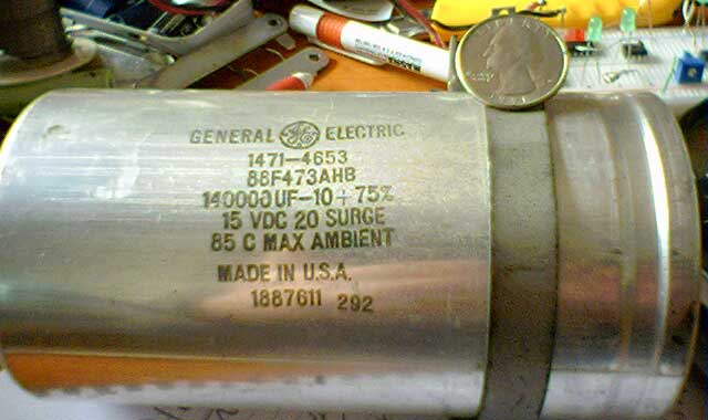
From the label you can see that its only 15V - 20V peak but is 0.14F !!! so I tough I can use 2 more in series and have a nice setup of around 45v 40000uF.
What do you whink?
Pablo
-
06-17-2005, 08:41 PM #10
Gold Member
- Join Date
- Aug 2004
- Posts
- 2849
Well you can, but the voltage would still be 15 VDC......hmmmm I wonder how the voltage rating is determined....I suspect it related to the ESR......
-
06-17-2005, 09:10 PM #11
Community Moderator
- Join Date
- Dec 2003
- Posts
- 24221
In series across 30vdc would be 15v across each cap.
Al.CNC, Mechatronics Integration and Custom Machine Design
“Logic will get you from A to B. Imagination will take you everywhere.”
Albert E.
-
06-17-2005, 09:26 PM #12
Registered
- Join Date
- May 2005
- Posts
- 925
If I put 3 in series it should be 45v and 46666uF. Is this correct?
is this a good idea or is better to build in parallel from say 10x 4700uFx50v ?
Pablo
-
06-17-2005, 09:45 PM #13
Community Moderator
- Join Date
- Dec 2003
- Posts
- 24221
The parallel way is the preferred way. Although the series fashion should work, keep in mind most electrolytic manufacturers quote a tolerance of -0 +100% !
Al.CNC, Mechatronics Integration and Custom Machine Design
“Logic will get you from A to B. Imagination will take you everywhere.”
Albert E.
-
06-18-2005, 07:07 PM #14
Registered
- Join Date
- Mar 2005
- Posts
- 1498
050618-1306 EST USA
peu:
It is not a good idea to just put two or more capacitors in series in order to solve a voltage rating problem.
Here is why:
The voltage on a capacitor is V = Q/C --- where V is voltage in volts across the capacitor, Q is the charge stored in the capacitor in Coulombs, and C is the capacitance of the capacitor in Farads. The charge transferred in a given time equals the integral of the current relative to time over that time period. In other words current is rate of flow of charge.
Connect two ideal capacitors (no shunt leakage resistance) in series. Make one capacitor twice as big as the other. The current flow to charge the capacitors is the same in both capacitors because they are in series and there is no shunt path across the individual capacitors.
Let capacitor C1 = 2 * C2. That is C1 is twice the capacitance of C2.
So if the change in Q is the same for each capacitor, which it will be, then the voltage on C1 is V1 = Q / ( 2 * C2), and the voltage on C2 is V2 = Q / C2, thus V1 = V2/2, or 1/2 the voltage on V2.
You can put a pair of equal resistors in series, one across each capacitor to force the steady state voltage to be equal, but that does not solve the transient problem.
As Al said "electrolytic manufacturers quote a tolerance of -0 +100%".
Your best solution is the 50 V capacitors in parallel.
.


 Reply With Quote
Similar Threads
-
How does a power supply work.
By ynneb in forum DIY CNC Router Table MachinesReplies: 1Last Post: 07-27-2011, 03:40 PM -
Diy Power Supply Choices
By berin in forum DIY CNC Router Table MachinesReplies: 11Last Post: 07-13-2005, 09:47 PM -
5 Volt Power Supply Tripping
By murphy625 in forum CNC Machine Related ElectronicsReplies: 13Last Post: 02-28-2005, 04:05 AM -
Choosing a Power Supply for Retrofit?
By pfeist in forum Uncategorised MetalWorking MachinesReplies: 4Last Post: 05-24-2004, 04:36 AM -
power supply test
By dlenox in forum DIY CNC Router Table MachinesReplies: 5Last Post: 04-28-2004, 02:06 AM
