


Hello everyone!
After considerable reading here on the forum I started drawing the project and here I have the first completed version ready to share with you. I'm not very good at 3D designing so I have no perspective view of the build, hoping you will understand the drawings.
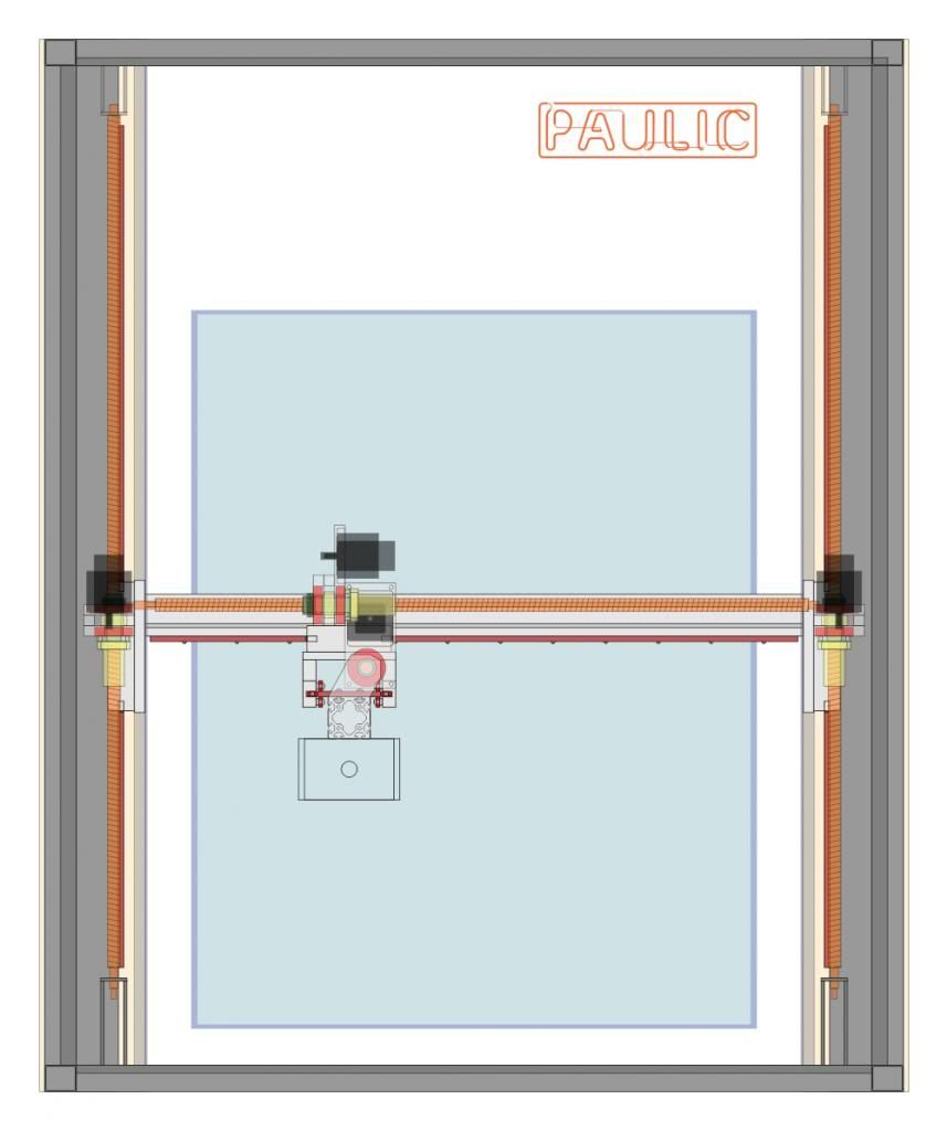
I had in mind two different constructions. First a classic design but with the gantry sliding under the table with one motor on x axis, to avoid missing steps and the gantry sliding unparallel. And second, this design, where I have total freedom regarding the size of the sheet or block that I have to carve. I want to use it for wood and lighter materials but also aluminum occasionally, The table will be independent from the machine, and I want to be able to adjust its height depending on the piece to be worked to be as close to the gantry as possible to avoid elasticity.
Then of course I was concerned about accuracy. I want to get it as accurate as possible but there must be some compromise when dealing with a large machine. This is why I chose to use ball screws with a rotating nut design.
Because I have a limited budget I will use the CNCRouterParts linear guides design. I hope to get a good precision having the steel flats rectified and aligned with epoxy resin.
I calculated the gantry at about 85kg (187 lbs) without spindle and am concerned about it being too heavy. Not sure what steppers and ball screw pitch to use. I would like to use the DIY stepper drives based on the THB6064AH chip designed by lucas. Now I'm not sure if I’ll use nema34 steppers, the maximum 50VDC/4.5A of the drives will be enough.
With this design I have a maximum travel of: X axis 1350mm (52”); Y axis 1070mm (42”); Z axis 650mm (25”).
And of course I have some unanswered or partially answered questions that will follow.
Any comments and suggestions are really appreciated!
Some specs:
- welded rectangular steel tubes for main frame (2x1.65 meters total);
- 120x10 mm carbon steel for X and Z guides and paired 60x10 mm for Y axis;
- 160x80 mm (1.25m) heavy aluminum extrusion for gantry and 80x80 mm (1m) for the Z axis;
- RM2505 or 2510 ball screws from china;
- rotating ball nut design with two 7207 angular contact bearings.
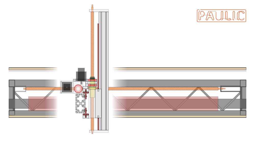
Color legend of the drawings:
light grey: aluminum
dark grey: steel
ochre: MDF
dark red: flat carbon steel for linear guides
red: ball bearings
orange: ball screws
yellow: ball nut
Results 1 to 9 of 9
-
02-17-2013, 02:45 AM #1
 Registered
- Join Date
- Jan 2013
- Posts
- 0
 My first CNC Router Build **PAULIC** (the machine)
-
02-18-2013, 04:26 PM #2
Registered
- Join Date
- Jan 2013
- Posts
- 0
Now I'm mostly concerned about the weight of the gantry. When I started the project I was thinking to have it between 100 and 150 lbs but now the nearly 200 lbs sounds heavy to me.
I don't know how to calculate the force (motor torque) I need to move my gantry.
If I have a 10 mm thread with a 1:1, I will need 1500 RPM to get 600 IPM rapids. I don't know if a stepper will spin that fast. And I will have 0.05 mm/step resolution which will be ok but not great.
Can anyone tell me what stepper torque do I need to move safely my gantry at 600IPM? I don't want to have everything up and running and watch the motors stalling...
Yes I know the magic word! SERVO but I don't have money for them.
-
02-20-2013, 04:54 AM #3
Registered
- Join Date
- Aug 2011
- Posts
- 999
That will be tough.
My machine has comparable gantry mass (approx 160-170 lbs), running on 15mm pitch ball screws. The resolution per full step is thus 0.075mm which does not sound much but is actually adequate to achieve 0.02 mm (or about 1/1000") reproducible position for most jobs with the Gecko 10 microsteps.
I started out with 1600in-oz high inductance steppers at 48V supply (not knowing what I was doing) which worked O.K. except max reliable speed was maybe 100-120 ipm. I changed that later to 72V supply which allowed maybe 150-200 ipm and finally I downgraded the steppers to 465 in-oz (still NEMA34) but only 1.6mH inductance.
That made a major difference. I could run rapids occasionally up to 1400 ipm but not so reliable and the remaining torque at that speed is miniscule. But I can machine at 250-300 and rapids up to 450ipm with no problems.
With a 10mm pitch lead screw I am skeptical if you can achieve such speeds never mind 600 ipm reliably. I suspect that gets you into servo territory. I stand corrected if somebody achieved that speed and resolution with a stepper and would be interested how.
Edit: I use an acceleration of 30in/sec^2. It is a good compromise for me in machining time, not losing steps and avoiding jerky movements.
-
02-20-2013, 06:53 AM #4
Member
- Join Date
- Apr 2007
- Posts
- 1955
Just adding to what Jerry said, keep in mind that the skate bearings + 1/4 inch thick cold rolled steel are good, but not really comparable to precision ground, rolling element, hardened rails + blocks. I have some of the ones you discussed, and I have no complaints, but I also have no illusions that they are more than "well done skate bearing assemblies".
Consider instead to use a screw like a 2525 (1 turn per 25mm of motion ). That gives you 25 / 200 = 0.125 mm per full step, and 0.01 mm per 1/10th step. This is honestly more accurate than your rail will be by quite a bit. It also keeps your rotation rates in the 200 or so rpm, which is convenient for 1:1 use with the nema 34 steppers and still obtaining reasonable torque. It might be possible to rapid 3x faster than this, but even then, I am not so sure.
Stepper motors in the 800 - 900 oz in area are about right for this setup. Gecko markets a high linearity, low inductance motor like this for I think around $ 150.
This is what I am planning to use in my build, so hopefully the numbers are more or less correct.
-
02-21-2013, 02:39 PM #5
Registered
- Join Date
- Jan 2013
- Posts
- 0
Thank you both for the input!
Jerry, when I came across your big bamboo thread I couldn't go to sleep before reading every single post and that was 4am. You have a lot of amazing ideas, especially the dust protection (that I will obligatory implement) and the sled table extension.
After spending several hours searching for stepper motors I figured out that is probably impossible to have a stepper with low inductance, low current and high torque, in my case I was searching for the best torque at max. 4.5A 50VDC and inductance below 5mH and there are below 400oz-in. Just for reference there are Sigmax (PacSci) nema34 at 830oz-in, 4.3A, 4.7mH or 520oz-in, 3.9A, 2.8mH.
While I don’t have the money for 7A gecko drives or very high performance steppers, I have to make some compromises.
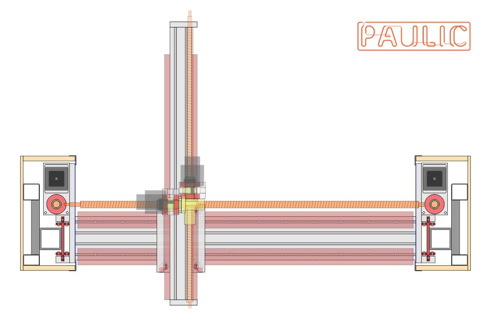
I will definitely get the 10mm pitch ballscrews for X and Y and probably 5mm (or the same 10mm??) for Z. Having the rotating ball nut I can play with different ratios. I am thinking about having two pair of pulleys attached, 2:1 and 1:2, being able to change the belt when I need high precision or force (with low speed). Then I will have for most jobs a 20mm/rev, 0.1mm/step and for small pieces, for precision or aluminum a 5mm/rev, 0.025mm/step. I’m not sure if with the DIY drive I can rely on the precision of microstepping positioning.
I took a closer look at your girl figurine in aluminum and the resolution is really impressive. I will be really happy to get there. Originally Posted by JerryBurks

You’re right the cold rolled steel you are buying in the US has -0.076mm for thickness and -0.2mm for 120mm width tolerances which is a lot! And here in Europe are probably similar. This is why I searched and found a place where they have a precision linear grinding machine with magnetic table up to 1.6m. I’m not sure what precision I will get but I’m sure it will be high. Originally Posted by harryn
Here is my rotating ball nut design cross-section with 2:1 and 1:2 ratio.

-
02-21-2013, 03:24 PM #6
Registered
- Join Date
- Jan 2013
- Posts
- 0
If I got it right, the drive must provide the peak current which is 1.41 times Amps/Phase. This means that with the 4.5A drive I can run only a 3.2A stepper at its full potential.
Maybe I can choose the Keling KL34H260-35-4B nema34, 465oz-in, 3.5A, 4.2mH. But I have doubts about this steppers being able to reliably move my 200lbs gantry. And moving it above 300ipm is out of the question I think. And at these speeds the rotating nuts does not make sense. Yes, the circle is round!
Probably the gantry stiffness is a little overkill and I may try to reduce a bit the weight.
Still trying to find alternatives...
-
07-17-2013, 12:09 PM #7
Registered
- Join Date
- Jan 2009
- Posts
- 265
How is it going? (the build)
I had a mental block for a ballnut rotating design, yours came up in a google search, i hope you dont mind if i copy? (the ballnut idea)
Cheers!
-
07-17-2013, 02:37 PM #8
Registered
- Join Date
- Jan 2013
- Posts
- 0
Hi D.L
My build is not progressing very well. I'm stuck with the linear guides, the steel flats I bought are not straight and it is hard ho have them grounded cheap at that length.
I haven't decided yet for my belt and pulleys type and therefore haven't machined the rotating ballnuts design. I'm concerned about the belt and pulley backlash, you can read more here.
There is one important aspect to be taken in consideration regarding my rotating ballnut design, putting both pulleys for easy changing the ratio will increase a lot !!! the moment of inertia which will affect the acceleration.
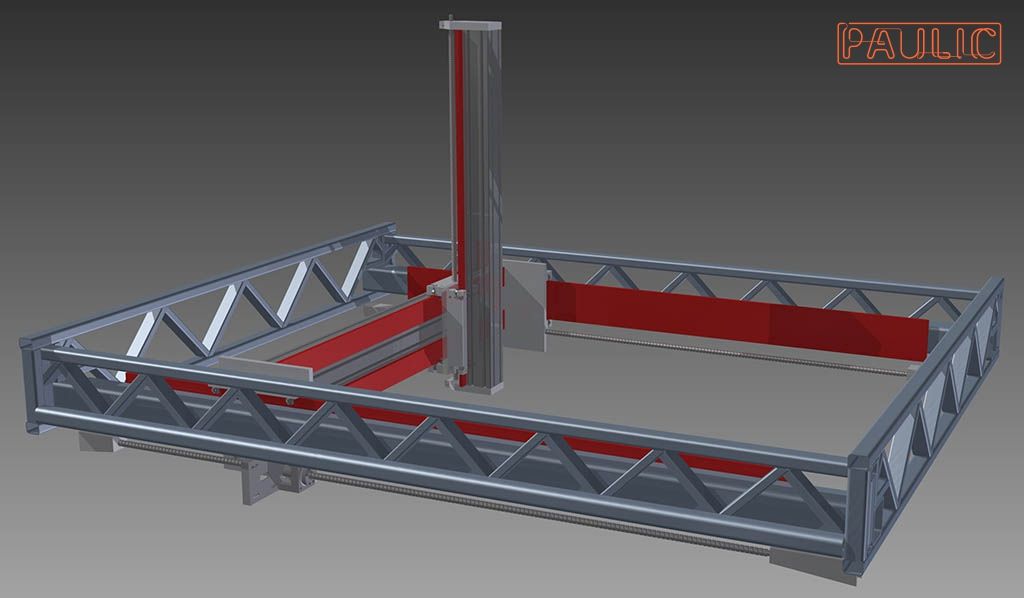
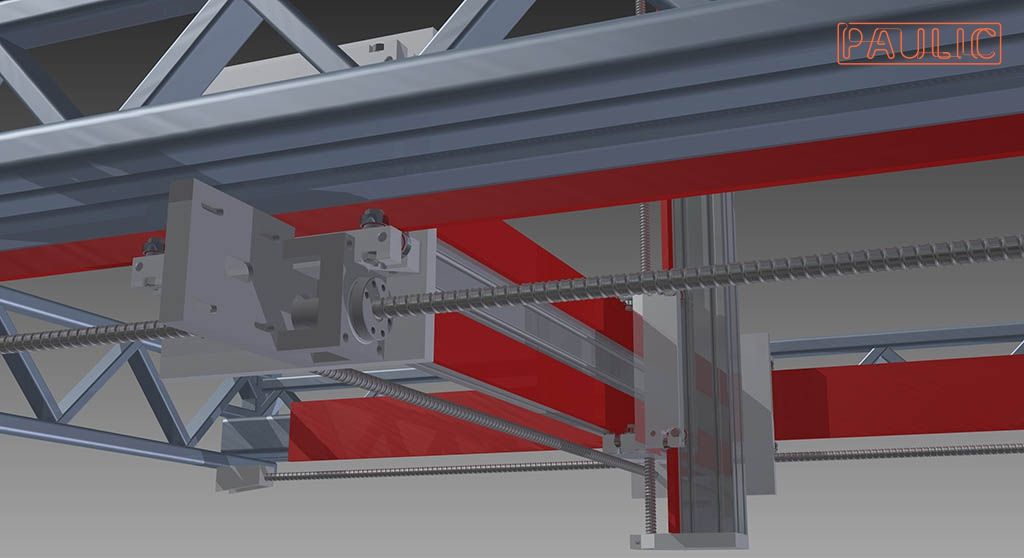
and here are some 3D renderings of my final design
-
07-17-2013, 05:51 PM #9
Registered
- Join Date
- Jan 2009
- Posts
- 265
yeah, welding distorts the hell out of everything. Even top tradespeople have problems with it, and square hollow section pipe usually is all over the place with taper and twist.
But don't give up, if you are committed to the build, you can shim under guides with strips of coffee tin, coke can or roof iron, 3 very useful sizes! Careful with the tin snips and fingers.
Also, maybe look for a slab of granite kitchen table offcut for a reference surface for measuring from. Cheap and flat.
I had ideas of rolling an angle grinder with cup wheel fitted and a few skate bearings along the granite, a portable surface grinder! Hah, just had the light bulb moment!

 Reply With Quote

Similar Threads
-
Need some direction to build a small machine to allow me to build a larger one
By Dman65 in forum DIY CNC Router Table MachinesReplies: 3Last Post: 01-05-2013, 05:24 AM -
Want To Build 4-Axys DIY CNC Milling/Router Machine
By mesyin in forum DIY CNC Router Table MachinesReplies: 7Last Post: 05-29-2011, 09:34 PM -
Newbie - To build or not to build Router/Plasma Table
By dfranks in forum Waterjet General TopicsReplies: 10Last Post: 04-08-2011, 05:16 AM -
CNC Router-20"x20"x4" Build or buy machine?
By cbstephenson in forum DIY CNC Router Table MachinesReplies: 3Last Post: 06-04-2010, 08:02 AM
