


Electronics:
420 oz/in steppers (3)
Keling 4030 drivers (3) I have them set to 1/4 microstepping.
Standard breakout board.
36v 6.6a power supply.
Controller software is emc2 run on Ubuntu 8.04
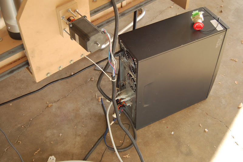
I wired four 12v PC fans into the supply for cooling. Not sure what voltage they're getting, but it's enough to run them all, so thats ok. Shopvac foam filter on the front for dust control. The case is just an old pos dell PC case.
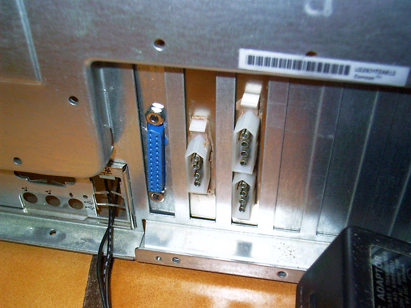
The motor wires are fitted with molex connectors. Since they're pretty long, I looped them through some RFI chokes a couple of times, too. Here's the brackets I made and the back of the case with the female molex connectors.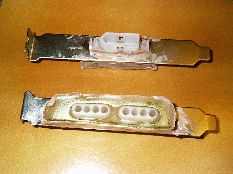
And of course, I have my SHINY BIG RED BUTTON just in case I mess things up real bad. Which has been known to happen with cnc machines.
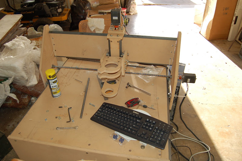
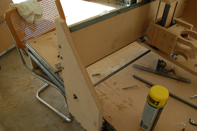
Machine mechanics...
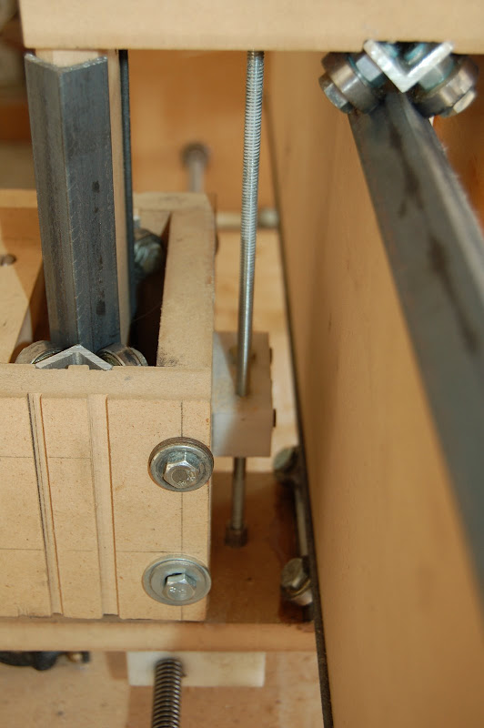
The rails are all 3/4x3/4x1/8 steel angle. All the parts are machined from 3/4 MDF. I (somewhat) accurately cut them out and drilled most of the holes using my first CNC machine, which I built by hand.
The linear bearings are aluminum angle (same size) with holes drilled and tapped to allow ball bearings to be fastened to them. In this case, your basic el cheapo roller blade ball bearings. I went with aluminum because it's easier to tap, accurately.
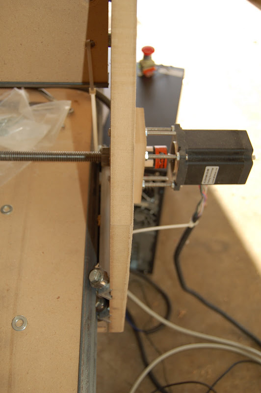
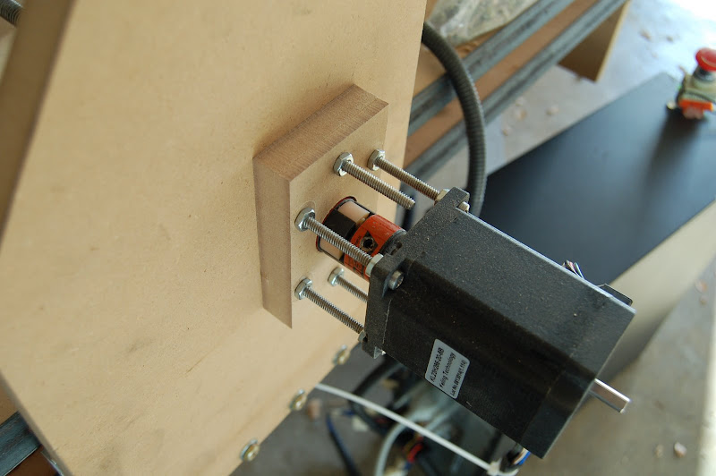
This machine, is a moving gantry style. Motion is supplied by turning a leadscrew against a transmission nut with a stepper motor.
X-axis transmission is 1/2-10 acme threaded rod.
Same for y-axis.
Z-axis is 1/4-20 allthread, tho I plan to replace that with 3/8-12 acme rod.
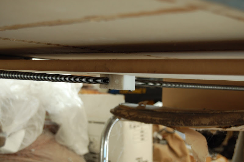
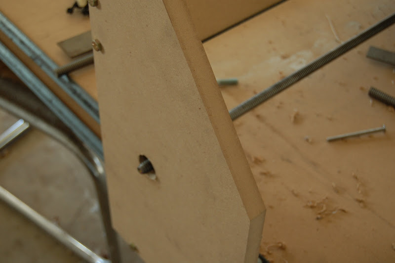
The transmission nuts are all homemade from acetal (type of plastic). I chose acetal because it's fairly hard but its also fairly slippery. So far, (though I haven't measured it yet with a dial indicator) I'm fairly certain there is NO backlash in any of the axes. Mostly because nothing is perfectly aligned. However, I have designed my transmission nuts to be anti-backlash nuts.
Diagram: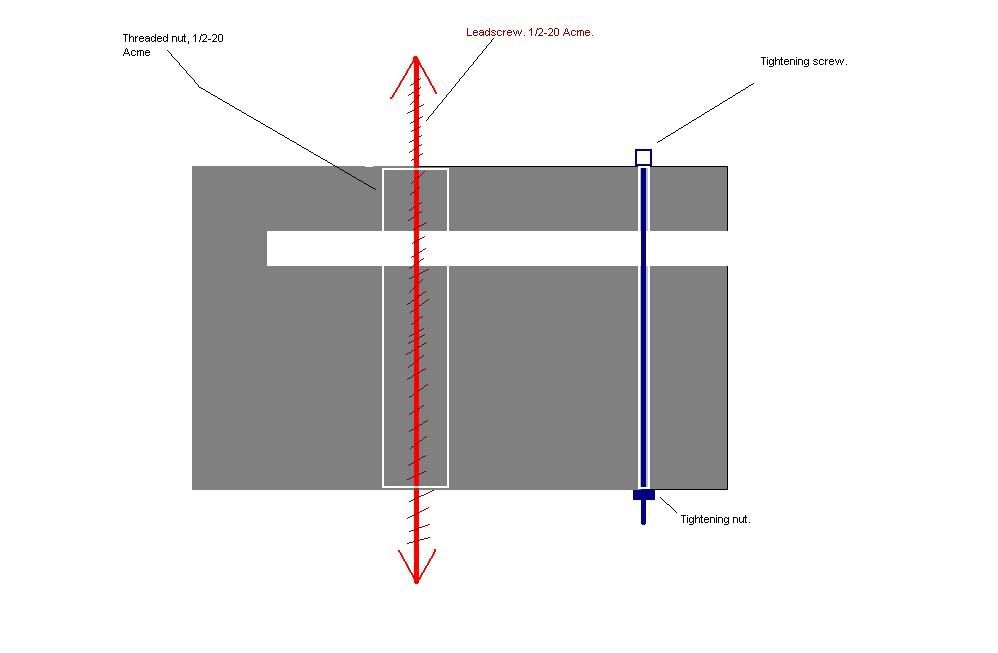
The tightening screw at the end of the "mouth" allows me to carefully bind the threads of the nut against the leadscrew. I ripped the idea off of someone else here on cnczone, so don't think I'm some kind of creative person. I isn't.
The table is a torsion box to prevent bowing as the gantry travels down the x-axis.
Oh yeah, final travel for each axis:
X-Axis ~49"
Y-Axis ~35"
Z-Axis ~9.5"
Now, the pics:
Machine results!
Mind you, it still needs some tweaking so everything is aligned a bit better but even so...
Top speeds before motors stall:
X-axis:96IPM!!!
Y-axis: 90IPM!!!
Z-Axis: 18IPM That's still better than the old machine but I'm going to replace it with a length of 3/8-12 Acme that I've got on order.
Compare that to my old machine which I had running at 18ipm, 18ipm, and 12ipm. I could probably get even better speeds, but my transmission nuts are not quite perfectly aligned between the holes for each axis. So the leadscrews are slightly binding against the threads of the transmission nuts.
The x-axis is the best, because I was able to drill and screw it to the bottom of the gantry while it was threaded onto the leadscrew. It was kind of a pita to do, tho. A flexible head flashlight would have helped a great deal.
I couldn't do that for the Y and Z axes. Not enough room to get a drill or screw driver in there. So I had to make pencil marks and then take it apart to attach the acetal transmission nut.
The z-axis... hm. What I think I'll do is ream out the holes on either end of the leadscrew. The holes that the outer race of the transmission bearings are supposed to ride against. Then I'll assemble the entire transmission with motor so that every part of the transmission is sitting where it wants to be. Then I'll fill in the space I reamed out between the bearings (top and bottom, both) with epoxy.
I can't really do that with the y-axis, because the bearings are facing horizontally to the earth. Sometimes I hate gravity. But I think I can live with 90IPM. Hell, I can't really machine anything but foam at that speed, anyways.
Stay tuned for a GOOD quality video of the beast in action in the near future. I stuck a crowbar in my wallet and ordered a logitech 9000 pro webcam. Mostly, I'm going to use it for 3D laser scanning. Yes, frikken lasers. Say it like Dr. Evil.
So what do ya'll suggest for fixing the binding issues I'm having? Do you think my epoxy-repair of the z-axis bearing blocks will work?
Results 1 to 5 of 5
-
01-09-2009, 05:26 AM #1
 Registered
- Join Date
- Jun 2008
- Posts
- 52
My second cnc build. Lots of pictures. A couple of problems.
-
01-09-2009, 08:28 AM #2
Registered
- Join Date
- Jun 2005
- Posts
- 179
Looking Great
Keep the photo's coming look forward to the video.
Andy
-
01-09-2009, 10:16 AM #3
Registered
- Join Date
- Oct 2008
- Posts
- 242
hey cool, your specs are very similar to mine, but better made :rainfro:
you're doing better than me, so I probably can't help much. I do have a question though - even though I have around 9 inches of z travel, the thickness of the material being machined will be restricted by the height of the y-screw. In reality, I can only put less than 3 inches of material under the gantry before the y-screw blocks it.
do you have a solution for this?
-
01-09-2009, 11:04 AM #4
Registered
- Join Date
- Jun 2008
- Posts
- 52
You could move the y transmission up and back. Have the y-axis transmission screw attached to the back of the "box" rather than to the bottom like it is on mine. Originally Posted by Jack000

You'll have to extend or attach bearing blocks and motor mount so they stick out behind the gantry, but that shouldn't be too big of a problem.
Or, you could just keep it the same, but have the Y axis rails higher from the table. Don't go too high, tho, as that will change the center of the gravity.
eta: come to think of it, really the second option is the only thing that will do what you're wanting. Simply getting the transmission screw out of the way will still leave you with the bottom y-axis linear bearing/support in the way. Just remember to lengthen your gantry and your x-axis linear bearings if you're going to move the y-axis up. This will give it a bit more stability.
-
01-09-2009, 08:16 PM #5
Registered
- Join Date
- Oct 2008
- Posts
- 242
thanks. I figured I might have to do that.
again, nice build!


 Reply With Quote
Similar Threads
-
lots of problems
By EHA in forum EdgeCamReplies: 11Last Post: 07-30-2008, 07:19 PM -
Started build on CNC Mill. Lots of pics, sorry.
By EvanZ in forum Uncategorised MetalWorking MachinesReplies: 3Last Post: 02-17-2008, 02:24 PM -
Couple of EMC2 G-code problems.
By MagooT in forum Post Processors for MCReplies: 11Last Post: 12-26-2007, 06:27 PM -
Steel C-channel Build - Questions and pictures
By olskool in forum DIY CNC Router Table MachinesReplies: 10Last Post: 07-07-2007, 07:31 AM -
Lots of Problems after reinstalling Galil card
By 69owb in forum CamSoft ProductsReplies: 10Last Post: 05-07-2007, 03:09 AM
