


I have designed a large moving table CNC router and would appreciate any observations about it's design and mechanical connections. The cutting volume is 1.5m x 3m x .95m. I intend to cut 3d shapes from low and medium density foam for theming which I will coat with epoxy or other hard skin.
I also posted the images of this design as part of another thread: http://www.cnczone.com/forums/showpo...3&postcount=10 but have added them here too if that's OK to get some design input.
Basically, the drive mechanism is R&P on all axes ala Mechmate with 7.2:1 geared Nema 34 steppers. Two steppers drive the moving table. The z axis is assisted against gravity by two cable retractors. The linear motion is comprised of Dual Vees riding on steel angle spot welded at 45deg on the support members. I've calculated the deflection on the gantry to be about .015 in approx based on 150lb y axis car and z axis assembly.
The moving table assembly will be bolted to the slab and leveled with the mounting bolts and aligned to the fixed gantry above. It seems like the most critical part of the construction is to align the angle iron tracks to the beams and to themselves. The gantry uprights as they exist don't seem to be a very elegant solution. The gantry gets it's rigidity form a friction bolted connection on each end.
I've not connected the gantry structure to the table because it results in a lot of extra steel and connections. I've noticed that a number of the large CNC machines rely on the slab connection. I'm only looking for a tolerance of about 1 or 2 mm. I expect to sand the finished product lightly before finishing it.
The areas I'm not so sure of in this design are the connections between the gantry and the uprights and the construction of the moving table. Any and all input is welcomed.
David
Thread: Need input on my design...
Results 1 to 5 of 5
-
02-22-2010, 09:04 AM #1
 Registered
- Join Date
- Dec 2006
- Posts
- 48
Need input on my design...
-
02-22-2010, 09:12 AM #2
Registered
- Join Date
- Oct 2005
- Posts
- 2392
Why not build one like this;
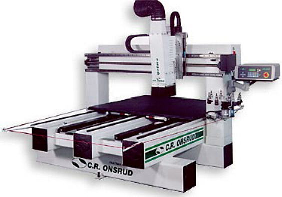
Absolute simplicity of chassis with welded steel tubing all the same size. I think it would be easier to build than your design and much more rigid etc.
-
02-23-2010, 01:43 PM #3
Registered
- Join Date
- Dec 2006
- Posts
- 48
Thanks for the pic. I looked at a few of the commercial moving table machines but decided to use less steel because I don't need the rigidity they have because I'm only cutting foam. The downside is that my thinner uprights would tend to vibrate when the gantry stopped suddenly, the reason I've braced them. But, I agree, they are beautifully simple machines. Most of the complexity in my design is in the y car and z axis. Originally Posted by RomanLini

-
02-24-2010, 02:50 AM #4
Registered
- Join Date
- May 2006
- Posts
- 804
Are you going to shape surfboards?
If so remember the cost factor,
The guy here does them for $55 per board
Can you build a machine and be price competitive?
We'll send you the work.Been doing this too long
-
03-05-2010, 03:57 PM #5
Registered
- Join Date
- Feb 2007
- Posts
- 54
My first thought is why not have the moving table move along the longest axis. That would reduce the length of the gantry beam by nearly half, and reduce deflection by almost a factor of four (deflection is proportional to beam length squared). Maybe you don't have enough floor space?
Second thought has to do with the design of the rollers/rails. It doesn't look like you have any compliance (spring action) on your rollers. It will be hard to make the distance between the upper and lower rail be exactly the same over the full length of the beam. If the rollers are all rigidly mounted, it will wind up very tight in some places, and wobbly in others. I'd mount the upper rollers rigidly, but make the lower ones spring loaded with some fairly heavy springs.
Third thought - increase the distance between pairs of rollers that ride on the long beam. Ideally the distance between those rollers would be close to the maximum vertical distance from cutter to the beam (when the cutter is all the way down). If you are extending the cutter down by 1.5 meters from the top of the beam, and the rollers are only 0.5 meters apart, the roller force is 3x the cutter force, and the cutter deflection is 3x the roller deflection.
Fourth thought - the machine seems fairly rigid for forces along the Y axis (the beam), especially if you increase the roller spacing as mentioned above. But imagine that the Y carriage is in the center of travel, Z is all the way down, and you apply a force in the X direction to the tool. The resulting force wants to twist the Y axis beam, and any twisting will be greatly magnified at the tool tip. The strongest beam shape for twisting is a circle, followed by a square, and then a rectangle. As the rectangle gets thinner, the beam gets more flexible. Any open shape, such as a channel or angle, would be much much worse than the closed rectangle you have. Welding end caps onto the beam will help. Making the beam shorter will help more, which gets back to the first suggestion.

 Reply With Quote
Similar Threads
-
design grad project: new breed of CNC design, need input
By nicanor76 in forum DIY CNC Router Table MachinesReplies: 11Last Post: 09-22-2009, 10:53 PM -
3 phase input VFD for single phase input?
By Redhead in forum Phase ConvertersReplies: 4Last Post: 02-27-2008, 05:30 PM -
design input for a CNC 'engraving' machine
By postvmvs in forum Uncategorised MetalWorking MachinesReplies: 2Last Post: 03-17-2007, 09:41 PM -
Looking for input on CNC table design
By yellow73bb in forum Waterjet General TopicsReplies: 2Last Post: 10-16-2006, 05:20 PM -
Second design attempt. Input wanted!
By ljoe1969 in forum DIY CNC Router Table MachinesReplies: 7Last Post: 09-13-2004, 12:23 AM
