


First off, thank you for looking at my idea for my new machine.
Will build it with MDF and progress to plastics
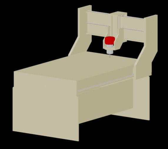
Total Spindle travel: 3'-1" in the Y, 4'-9" in the X, 8" in the Z
I plan on turning the nut on the X lead screw instead of turning the screw.
I already have acme 1/2-10 screws. One is 6', the other is 4' since I knew I would be using those two sizes. The Z axis has not been bought yet.
The main issue I am wanting to talk about is the gantry, and if I will be able to achieve 8" (I am really wanting 6 at a min).
I am willing to explode any part of this design so people an see what I am doing, I am an engineer so I want to get it right during design instead of trying to do it on the fly (even though I know that will happen as well).
Once again, thank you for looking.
Results 1 to 20 of 28
Hybrid View
-
03-24-2009, 11:31 PM #1
 Registered
- Join Date
- Aug 2008
- Posts
- 33
Just want some constructive criticism
-
03-25-2009, 03:33 AM #2
Registered
- Join Date
- Aug 2008
- Posts
- 33
Ok, so people are looking but nothing constructive to say about it...I guess that's a good thing. What do the (at last count) 31 members that have looked at this, think about the gantry? Do you think I will get 8 inches of travel without any problems? Screws are my friend here, and I have design enclosure in the past, so I knew how to make something ridged.
Here is some more info...
The gantry is 3' tall from the bottom tip to the top tip and 4'-2" wide. The side pieces will be doubled to help with strength. The skirts of the side pieces are 16" in length. I am thinking this will be wide enough to support such a tall gantry. This and the 16 bearings per side...
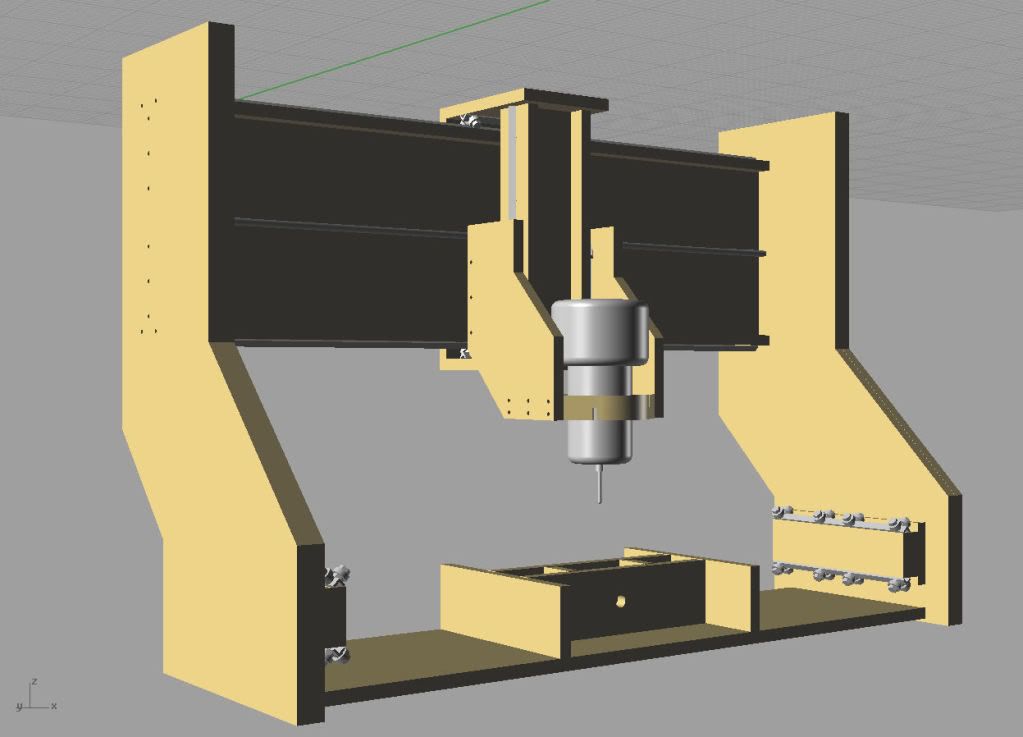
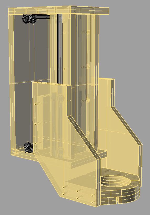
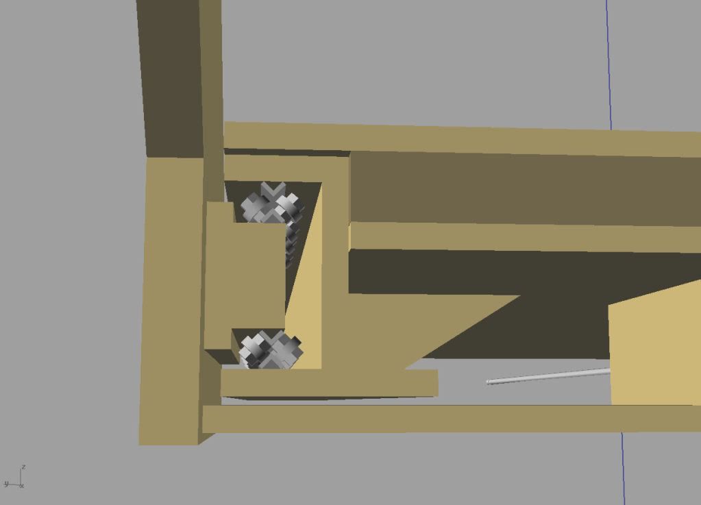
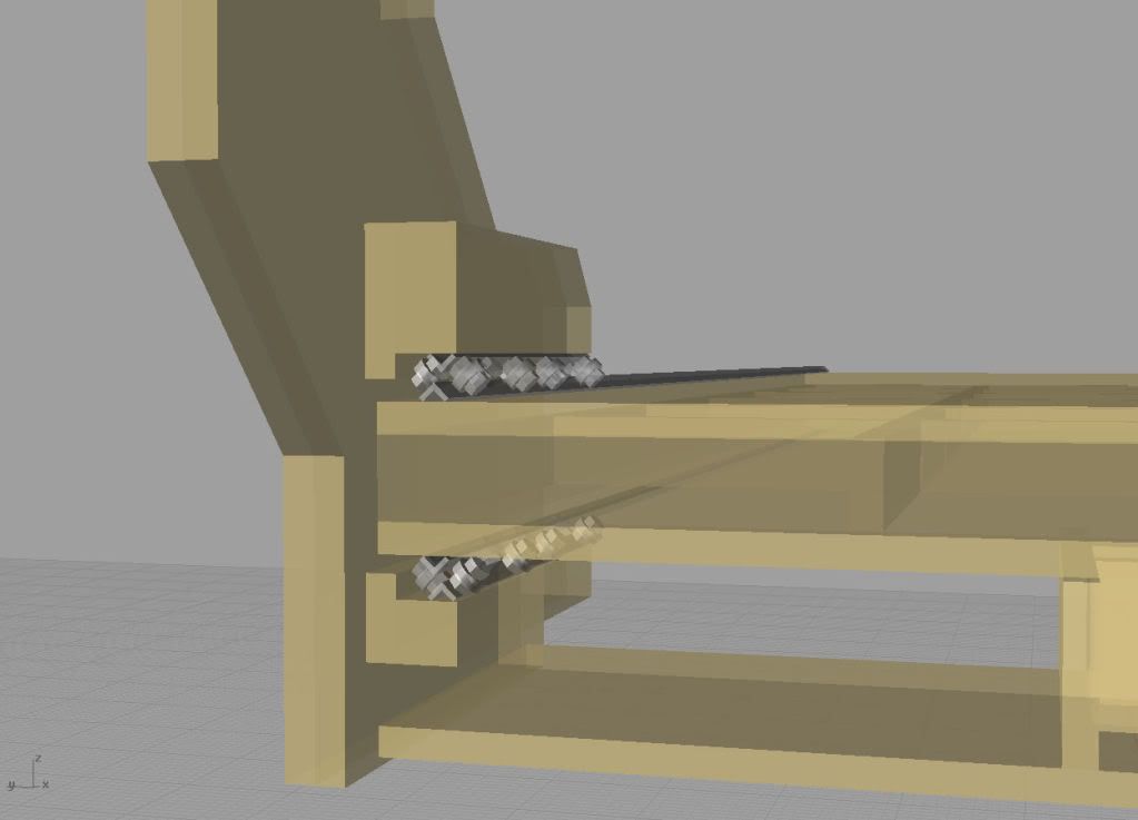
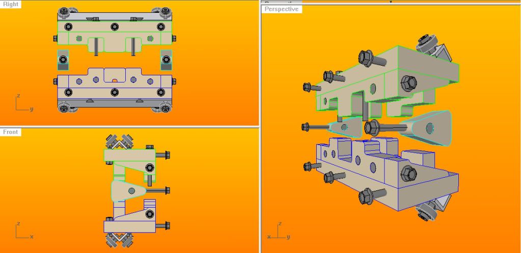
I plan on putting 16 bearings per side, 8 on top, 8 on bottom as shown in the picture below. I feel as though this will help evenly distribute the gantry weight along the rail for a smooth ride. This picture also shows the enclosure for the stepper motor, belt drive and acme nut (not pictured at this moment):
The Shuttle has a 4" in diameter hole for a router, is 8-3/4" wide, 11" deep, and 12" tall. The Shuttle will ride on 4 bearings on each side.
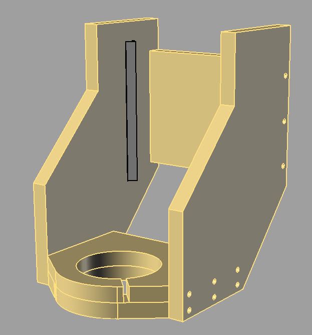
The Z axis allows for 8-1/2" of total travel, but my stopping point is 8". The Z axis shuttle will ride on 4 bearings a piece on both top and bottom in the 7 axis:
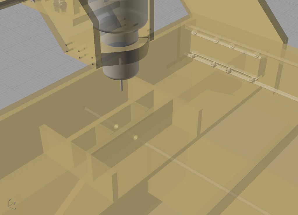
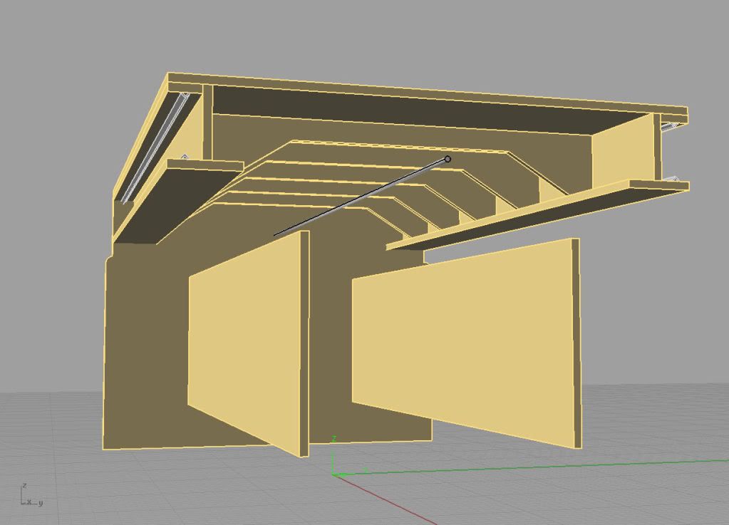
To give a better idea of how to solidify the table, I have removed the side to show a "gut shot". Here you can see the ribs holding the table. I gave it a rib effect so that the lead screw drive box will be able to pass under the ribs without any problem. The thinnest point of the rib is 2".
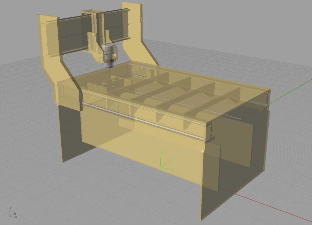
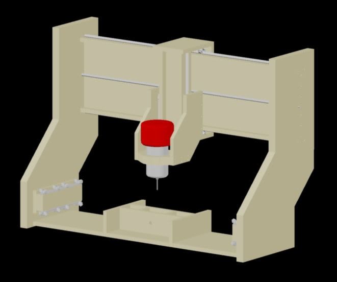
Finally, here is a ghost image of the whole table:
-
03-25-2009, 07:10 AM #3
Gold Member
- Join Date
- Dec 2004
- Posts
- 1865
Looking good.
The only real problem that I see is that all the weight of the gantry will be resting on the bottom v rail. The v-rail is mounted to the bottom web of your "I" beam. The "I" beam is made from MDF and will either tear it self loose or be way too flexible.
You could brace from the I beam flange to the center cross brace boards or even better, move them to be underneath the flange.
I think that the 16" wide base of the uprights will be wide enough to support the gantry.
I would also consider rounding some of those corners where you will drag your skin across them while using the machine. Even if you are cutting the machine with a circular saw at least dice the corners at 45 degrees to make it more comfortable to use.
If you don't already have a roto zip, get the one with the metal nose housing as the plastic ones will flex noticeably under the stress of an 1/8" cutter.
MikeWarning: DIY CNC may cause extreme hair loss due to you pulling your hair out.
-
03-25-2009, 03:55 PM #4
Registered
- Join Date
- Aug 2008
- Posts
- 33
...and those are thing things I am talking about. You can stare at something long enough that you lose track of the simple things. As soon as you mentioned that, I brought up my drawings and realized I had not supported the lower brace. Originally Posted by TOTALLYRC

Me moving the braces on the bottom to under the I beams would allow me to also do my next step of putting drawers under the machine for storage.
Now it makes me wonder what else I forgot... :-(
-
03-25-2009, 04:32 PM #5
Community Moderator
- Join Date
- Mar 2003
- Posts
- 35538
You need to add a bottom panel to create a torsion box. Just the ribs alone will not be enough to keep it from warping and twisting. But a torsion box will remain flat, even with a lot of weight on it.
Gerry
UCCNC 2017 Screenset
http://www.thecncwoodworker.com/2017.html
Mach3 2010 Screenset
http://www.thecncwoodworker.com/2010.html
JointCAM - CNC Dovetails & Box Joints
http://www.g-forcecnc.com/jointcam.html
(Note: The opinions expressed in this post are my own and are not necessarily those of CNCzone and its management)
-
03-25-2009, 05:05 PM #6
Gold Member
- Join Date
- Dec 2004
- Posts
- 1865
Hi GER21, now that you mention it, and since I am sitting in front of mine, that is exactly how mine is built. wooden I beams with sheets top and bottom. Originally Posted by ger21
MikeWarning: DIY CNC may cause extreme hair loss due to you pulling your hair out.
-
03-25-2009, 07:25 PM #7
Registered
- Join Date
- Aug 2008
- Posts
- 33
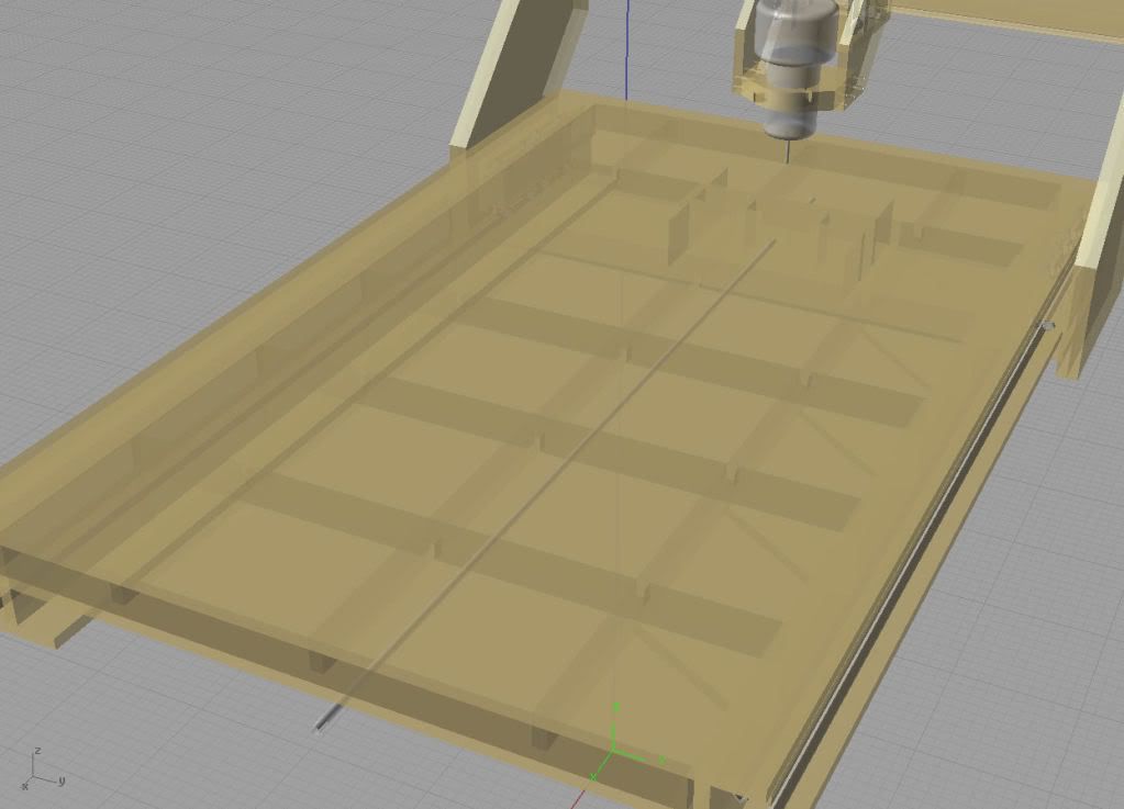
Taking the advice given so far, I have went back and modded the table to be a torsion box under the cutting area (between the rails). If you think the whole table top should be a torsion style box, then I will rethink what I'm doing:
But my issue now is still the rails and what Mike said about the rails and the amount of weight that would be put onto the bottom part of the I beam.
I originally was going to put supports under the I-beam until I remember that the gantry's bottom has to pass under them. So I'm still thinking about what to do. I thought about trying to integrate the rails into the torsion box, but then realized that I would be faced with (kinda) the same problem as now and that I would be putting strain on where the sides of the gantry meet the rails because that would go from 3" inches down to an 1"...
-
03-25-2009, 07:37 PM #8
Registered
- Join Date
- Aug 2008
- Posts
- 33
Ok, so staring at the design long enough...I MIGHT have found a solution to my problem...will post again soon.
-
03-25-2009, 08:12 PM #9
Registered
- Join Date
- Aug 2008
- Posts
- 33
Well, I thought I had fixed the problem...and I did, but now I have caused another "problem":
I moved the rails from under the table, and integrated them onto the top and bottom of the torsion table (since I knew that would hold it), but now I do not like the fact that the rails are exposed to traffic. I feel as though if I left them like this, they will get damaged in my shop.
Oh well, still looking for ideas. Will keep you posted...
-
03-25-2009, 08:44 PM #10
Registered
- Join Date
- Mar 2007
- Posts
- 122
X-axis Rails
Hi J,
In your Post #7 above, bottom picture, have you considered making the torsion box deep enough so that the bottom of the torsion box would fit just under your setup for the rails?
In this way, you would have double the wood you now have. If it comes to push and shove, you could add angle iron between the bottom rail and the torsion box.
Of course, this would require you to lengthen the legs of the gantry to accommodate the extra depth.
It's just a thought and may not work for you or be to your liking.
Al
-
03-25-2009, 08:49 PM #11
Registered
- Join Date
- Aug 2008
- Posts
- 33
See, that makes me feel better...I was in the middle of modeling that whenever you posted. I feel as though now I am going down the right path. Originally Posted by Santa Fe Al
Thanks Al!
J
-
03-25-2009, 08:29 PM #12
Registered
- Join Date
- Aug 2008
- Posts
- 1166
Is the gantry top cross bar just one piece of MDF with small pieces at the top and bottom for the Y rails? If so, you might want to think about making that into a torsion box type structure as well. But it really just depends on how rigid you want your structure to be.
On your Z-axis, in my somewhat limited experience (just getting my router going), even if you have 8" of Z travel, the question is can you use it all on the part you're cutting. The answer is not likely. It looks like you've taken care of getting the stationary portion of your Z axis high enough above the table. However, it doesn't appear you have enough room for a long cutter to clear your material. So you could have 8" of Z travel with a short cutter, but this would limit your cutting area / depth based on your part geometry. As you went deeper, your router and router holder would start running into the material around it so you would not be able to cut in any location - only in the middle of a pocket, for example.
-
03-25-2009, 08:48 PM #13
Registered
- Join Date
- Aug 2008
- Posts
- 33
Ok, so I'm a DA and I can't help it...I realized what everyone was trying to tell me:
-
03-25-2009, 11:58 PM #14
Community Moderator
- Join Date
- Mar 2003
- Posts
- 35538
You need a way to adjust tension (compression?) on the bearings. As shown, the MDF will bend down on the bottom where it's carrying the weight. Some type of reinforcement underneath might help. You might also have an issue with the top layer curling up.
Gerry
UCCNC 2017 Screenset
http://www.thecncwoodworker.com/2017.html
Mach3 2010 Screenset
http://www.thecncwoodworker.com/2010.html
JointCAM - CNC Dovetails & Box Joints
http://www.g-forcecnc.com/jointcam.html
(Note: The opinions expressed in this post are my own and are not necessarily those of CNCzone and its management)
-
03-26-2009, 02:46 AM #15
Registered
- Join Date
- Aug 2008
- Posts
- 33
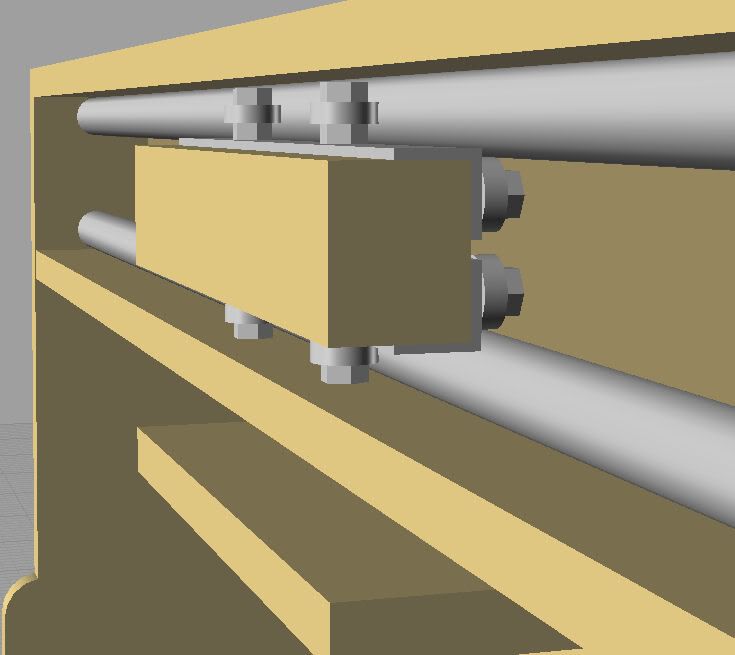
If I use steel pipe, like shown in this model, would I still need the tension screws? Originally Posted by ger21
-
03-26-2009, 04:11 AM #16
Gold Member
- Join Date
- Dec 2004
- Posts
- 1865
You are going to want some adjustability because it it made from wood and it is inherently less thermally stable than say steel. It will be affected by moisture too.
Keep drawing, you will get it the way you want eventually.
MikeWarning: DIY CNC may cause extreme hair loss due to you pulling your hair out.
-
03-28-2009, 03:05 AM #17
Registered
- Join Date
- Jun 2008
- Posts
- 203
Rabbithole
After sealing the MDF, I haven't noticed any problems with 'curling' and my build is very simular. Originally Posted by ger21
My advice for tensioning the bearings is to keep it simple, you would be amazed at the rabbit hole you can fall down if you start over thinking details. This is something you can rework for real rather that speculate over details that are almost impossible to execute. I have two washers currently tensioning my bearings. Here is my rabbit hole, however...
-
03-28-2009, 11:06 PM #18
Registered
- Join Date
- Aug 2008
- Posts
- 33
Yeah, I have decided on just doing washers for now...
and yeah, you are definitely looking at a deep, Alice in wonderland, rabbit hole...
-
03-26-2009, 12:10 AM #19
Registered
- Join Date
- Sep 2007
- Posts
- 740
If you haven't already look at Joes2006. There are a lot of good ideas in that machine that you could adopt for yours.
-
03-26-2009, 04:20 PM #20
Community Moderator
- Join Date
- Mar 2003
- Posts
- 35538
It's very unlikely that you'll be able to build it so precise that no adjustment is necessary. That, and you'll want to preload the bearings tightly to the rails or pipe. If you don't have them preloaded, flexing of the machine will allow some of the bearings to move away from the rails. You don't want that.
 Gerry
Gerry
UCCNC 2017 Screenset
http://www.thecncwoodworker.com/2017.html
Mach3 2010 Screenset
http://www.thecncwoodworker.com/2010.html
JointCAM - CNC Dovetails & Box Joints
http://www.g-forcecnc.com/jointcam.html
(Note: The opinions expressed in this post are my own and are not necessarily those of CNCzone and its management)

 Reply With Quote
Similar Threads
-
Review/Criticism requested on photos of G201 Wiring
By Gerald_D in forum Gecko DrivesReplies: 3Last Post: 07-17-2005, 06:03 PM
