


Alright. It was just something I was thinking aboutOriginally Posted by FandZ

As for a question asked earlier, how thick of aluminum should I use? Would 3/8" be sturdy, or should I just spend the extra on 1/2"? I know the stronger the better, but I would like to save some money where possible, without skimping on the quality of the machine.
I'm working on centering the Z-Axis over the pillow blocks the best I can at the moment. Will post results once I'm done.
Any more suggestions for modifications to my design? Any ideas for "feet"? Does it really matter what I do?
Thanks,
- Jesse
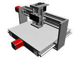
EDIT: Just reworked the design and swapped the Y-Axis with an 18" leadscrew. That brings the Y Travel up to about 13.5". This gives me a working area of approximately 10.75"x13.5", which is significantly larger, with very little extra material. May consider going this direction.
Results 21 to 40 of 69
-
02-28-2010, 09:14 AM #21
 Registered


- Join Date
- Aug 2009
- Posts
- 392
-
02-28-2010, 10:41 AM #22
Registered
- Join Date
- Nov 2009
- Posts
- 106
You could also just extent the table out past the rails to get the lost space back. That's what I'm planning to do with my machine anyway. Originally Posted by FandZ
-
02-28-2010, 10:52 AM #23
Registered
- Join Date
- Nov 2009
- Posts
- 106
I'm just the opposite, I like the belt setup better. I don't see any disadvantages over a direct drive and I can name a few advantages. Originally Posted by FandZ
1. Ability to change out the pulleys for gearing up or down.
2. Alignment is less critical as the belt is more forgiving than a coupler.
3. Keeps the height of the machine low. The higher up that 2lb motor is the more moment its going to cause when accelerating back and fourth, may not sound like much but try holding a 2lb weight centered in your hand and move it back and forth quickly then try it again holding a shaft with the weight positioned a couple inches above your hand.
-
02-28-2010, 05:18 PM #24
Registered
- Join Date
- Oct 2008
- Posts
- 1147
Why not just design it right the first time? It doesn't add much complexity to the build. Besides, having your bit between your X axis will make a stronger machine and your X axis rollers will thank you for it. Your cuts will be better too. Originally Posted by stangtjk
1. gearing up and down is good for servos. The up part at-least. I believe he is going with steppers and a G540. Originally Posted by stangtjk
2. Motor Alignment is not critical. The alignment of the drive screw is and that won't change with a belt.
3. Any sort of balance you get will be thrown off by the spindle. It may even work better for rapids. It could counter balance your spindle. Most people don't raise the Z axis to the top or middle when you rapid. You do it just above your stock to save time.
Gears do make for a nicer presentation. Having a more compact machine is nice. Using gears to drive two drive two screws can be great. On a Z it just seems like a waste of time to me.
-
02-28-2010, 09:18 PM #25
Registered
- Join Date
- Nov 2009
- Posts
- 106
I'm not sure I agree with that, maybe I'm looking at this wrong but the way I see it all forces resulting from the cutting tool are going to be transferred to the x-axis through your gantry beam. Therefore it would be more important to have the gantry beam centered between the x-axis bearings than it would be for the spindle. The further from center the gantry beam is from the x-axis bearings the more moment its going to cause. Originally Posted by FandZ
I think it would be useful for steppers as well. If you pick a 10tpi lead screw for the z and after using it for a while you decide you want more speed its a lot easier to swap the pulley than the lead screw.1. gearing up and down is good for servos. The up part at-least. I believe he is going with steppers and a G540.
Not sure about that, flex couplers can only compensate for so much misalignment.2. Motor Alignment is not critical. The alignment of the drive screw is and that won't change with a belt.
In general that makes sense. But with the z axis travel of this machine the spindle is not going to drop low enough to compensate.3. Any sort of balance you get will be thrown off by the spindle. It may even work better for rapids. It could counter balance your spindle. Most people don't raise the Z axis to the top or middle when you rapid. You do it just above your stock to save time.
I feel like I'm arguing with everything you say lol. Just want to say that is not my intentions I'm only expressing my personal opinions.
-
03-01-2010, 12:21 AM #26
Registered
- Join Date
- Oct 2008
- Posts
- 1147
The forces at the spindle work up and around to the x axis rollers like a big question mark "?" ... It's a lever effect. the closer in the middle the better it'll all play. Originally Posted by stangtjk
I'm using 1/2 10 acme screws on my Z axis with my router. I can rapid on it at the max my current pc will allow. 135ipm. But of course I don't do that. I think I turned it down to 90 or 75ipm. I keep playing with the plunge speed. I will be upgrading it to a faster screw to get more force and speed at a lower RPM range for working in metal. The thing I can tell you is once you get your machine squared and your software calibrated, you don't want to change anything out.
You have to trade resolution for speed with steppers. If 3d is your thing and you are using a stepper then you will not want to sacrifice resolution. A 2 start screw works out to a nice balance. If 3d is your main thing then servo's are a much better choice.
Right now my steppers are mounted against plates that have holes that don't match, meaning that they are aligned as good as I can get them and then bolted down as tight as I can. I'm getting cuts that are in the .005 range for accuracy. Being off a couple of degrees won't hurt anything with a good coupler.
-
03-01-2010, 04:26 AM #27
Registered
- Join Date
- Nov 2009
- Posts
- 106
I understand how the forces work, I just graduated with a BS in mechanical engineering. It's been a while since I've taken statics so if I'm wrong about this someone point it out and I'll kick myself in the ass and go brush up on my statics.
This is going to be difficult to describe in words so bear with me. Regardless of where the spindle is relative to the x-axis bearings there with be resultant forces and moments acting on the gantry beam. Imagine the sides of the gantry are L shaped with the 2 bearings on the bottom of the L on each end and the gantry beam is connected to the top of the L. The resultant forces from the spindle are going to be acting on the top of that L whether the spindle is between the 2 bearings or not. Now think of the gantry side as an upside down T again with bearings on each end and the gantry at the top. Now those same forces are going to be acting evenly between the 2 bearings. So like I said before it would be more important for the gantry beam to be centered between the bearings than the spindle. Centering the spindle would give you more cutting area if your rails are the same length of the table but to get it back you would just need to extend the table a little past the rails.
-
03-02-2010, 05:17 AM #28
Registered
- Join Date
- Aug 2009
- Posts
- 392
Thanks for all the opinions everybody. The only reason I like the belt and pulley option is for the reason mentioned: if I decide I want faster Z-rapids, I'll be able to gear it with a pulley that costs a couple dollars, rather than hunt down a new lead screw.
I messed around trying to compress the Z axis the best I could, and angled the gantry uprights a bit. Ideally I'd like to get it back ~1" or so further, but it's closer to centered than it was.
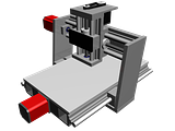
I also quickly threw together a rig with an 18" lead screw replacing the 12" on the Y-Axis, and this gives me a lot more cutting area. Both designs are under consideration.
Thanks,
- Jesse
-
03-02-2010, 05:33 AM #29
Registered
- Join Date
- Oct 2009
- Posts
- 272
Size does matter...
Jesse B,
Just ask any women. I kid. No I don't.:devious:
Seriously, I don't think building the bigger Y-axis will increase your build cost all that much. However, building a second machine to obtain that cutting envelope WILL cost much more. Just MHO.:idea:
Randy,I may not be good....
But I am S L O W!!
-
03-02-2010, 05:40 AM #30
Registered
- Join Date
- Aug 2009
- Posts
- 392
You always give the best advice:cheers: Originally Posted by DIYaholic
On a more serious note I'm seriously considering switching over to the larger design. I'm still trying to figure out what I'll be doing with this thing, which will be a pretty major part of my decision. I'll also have to work out the difference in cost between the two machines. As little as it may be, every dollar counts when you're poor
Thanks,
- Jesse
EDIT: Did some quick calculating. Assuming I didn't miss anything, it'd cost me $61.18 + additional shipping for the upgrade. So let's say $100. Not too bad if you ask me
-
03-04-2010, 04:21 PM #31
Registered
- Join Date
- Aug 2009
- Posts
- 392
A question I asked earlier, but seems to have been overlooked.
Is 1/2" aluminum overkill? Would 3/8" be enough, or should I stick with 1/2"?
Thanks,
- Jesse
-
03-04-2010, 09:10 PM #32
Registered
- Join Date
- Nov 2009
- Posts
- 106
It really depends on what you're expecting from your machine. You're not going to see really high cutting forces milling pcbs so for that application you're probably not going to see a noticeable difference between using 3/8" or 1/2".
Deflection is calculated using 4 parameters:
1. Force being applied (not sure what the cutting forces will but its not effected by your design so consider this fixed)
2. Length (determined by your design so unless you want to change designs consider it a fixed number as well)
3. Modulus of elasticity (depends on the material being used in this case it's aluminum so again this is a fixed number)
4. Moment of Inertia (This is the one number you have the most control over)
The moment of inertial is calculated using the cross section of the object, in this case a piece of plate. The moment of inertial for a solid rectangular cross section is I=bh^3/12, b being the base and h the height. So the moment of inertia of a piece of plate will be much higher standing on its edge than laying flat. In turn a piece of plate is going to have much less deflection in one direction than the other. That shouldn't come as much surprise, lay a ruler flat and you can bend it downward really easy, turn it on its edge and you cant. Now take 2 rulers stacked on top of one another and you get the same results. Try again holding one ruler perpendicular to the other like a T, you still have the same amount of material but you've increased the stiffness in the weak direction substantially.
That was my long winded way of saying adding a rib or gusset to the back side of a 3/8" plate would increase the rigidity of the machine a lot more than switching to 1/2" plate.
-
03-05-2010, 02:07 AM #33
Registered
- Join Date
- Oct 2009
- Posts
- 272
 Use the force Luke!
I haven't looked into deflection, forces and etc., but everything stangtjk said seems to make sense. I would go with the 3/8" plate (a rib or gusset), and if your resulting cuts are not to your liking... "Just blame stangtjk". lol.
Sorry stangtjk, I hope getting thrown under the bus didn't hurt much.:wave:
Jesse B
You say that now..... Just wait till I'm wrong.You always give the best advice:cheers:
I thought I was wrong once...But I was mistaken. lol.
Randy,I may not be good....
But I am S L O W!!
-
03-05-2010, 02:39 AM #34
Registered
- Join Date
- Aug 2009
- Posts
- 392
Awesome, thanks for the help guys. I'm working on changing my design to incorporate this new feature
One quick question however. I realize what you mean by gusset, but what materials are we talking about here? Do we mean just another piece of 3/8" aluminum perpendicular to the existing pieces, or simply some aluminum/steel angle bolted on?
Thanks,
- Jesse
-
03-05-2010, 03:29 AM #35
Registered
- Join Date
- Feb 2010
- Posts
- 331
could be either. another 3/8" piece would be stronger. thats probably what i would do. Originally Posted by Jesse B
also i can say x2 on what stangtjk said. i have been calculating the forces on mine and that is how i am doing it.
-
03-05-2010, 05:28 AM #36
Registered
- Join Date
- Oct 2009
- Posts
- 272
Here's my angle on this!
I'd let a deflection calculator make the decision between the 3/8" plate and the angle for a gusset. Just a hunch, but I would think angle would be more ridgid than a similar size/weight peice of plate.
I could be wrong, (it's happened before, but not usually). lol.I may not be good....
But I am S L O W!!
-
03-05-2010, 05:31 AM #37
Registered
- Join Date
- Aug 2009
- Posts
- 392
http://www.engineersedge.com/beam_be...m_bending2.htm
That's the calculator I was using. I can find all the variables except Moment of Inertia. How do I derive this number?
Thanks,
- Jesse
-
03-05-2010, 05:41 AM #38
Registered
- Join Date
- Nov 2009
- Posts
- 106
Each of these would accomplish the same thing. With out doing the calculations and knowing what amount of deflection is acceptable to you I cant really say what you should use. I big thing to keep in mind is how you're going to attach it. If you can weld aluminum you could easily attach another piece 3/8" plate. If you're bolting it together it would probably be easier to bolt on a piece of angle or two. If you're bolting something on it wont matter if you use steel or aluminum but here's something to think about, the modulus of elasticity of steel is 3x higher than that of aluminum and there for 3x stiffer for a part of the same dimensions. Weight for weight its pretty much a wash between the 2 but you need roughly 3x the amount of aluminum to equal steel.Do we mean just another piece of 3/8" aluminum perpendicular to the existing pieces, or simply some aluminum/steel angle bolted on?
-
03-05-2010, 05:43 AM #39
Registered
- Join Date
- Aug 2009
- Posts
- 392
I was just thinking of drilling/tapping holes for the alum plate, but angle would work just as well. Originally Posted by stangtjk
The weight difference between 3 feet of steel angle and 3 feet of aluminum angle is negligible.
Thanks,
- Jesse
-
03-05-2010, 05:50 AM #40
Registered
- Join Date
- Nov 2009
- Posts
- 106
The moment of inertia will depend on the shape and orientation. As I said before the moment of inertia for a solid rectangular cross section is I=bh^3/12. For a hollow rectangle its the same equation but you subtract the moment of inertial of the hollow space. For other geometries it gets more difficult especially for unsymmetrical stuff like a T. Google area moment of inertia, That should get you on your way. DON'T mistake this for mass moment of inertia, totally different thing. Originally Posted by Jesse B

 Reply With Quote

Similar Threads
-
Need input on my design...
By glintid in forum Mechanical Calculations/Engineering DesignReplies: 4Last Post: 03-05-2010, 03:57 PM -
design grad project: new breed of CNC design, need input
By nicanor76 in forum DIY CNC Router Table MachinesReplies: 11Last Post: 09-22-2009, 10:53 PM -
G540 input not working?
By stoneyreef in forum Gecko DrivesReplies: 1Last Post: 05-08-2009, 07:52 AM -
design input for a CNC 'engraving' machine
By postvmvs in forum Uncategorised MetalWorking MachinesReplies: 2Last Post: 03-17-2007, 09:41 PM -
Looking for input on CNC table design
By yellow73bb in forum Waterjet General TopicsReplies: 2Last Post: 10-16-2006, 05:20 PM
