


Hi Folks,
I am an engineer working on my own design for a CNC hotwire machine for my own use. I have been talking to a couple of people in my area about their hotwire and router machines and have received some great input with regards to my machine. Let me first lay out my goals:
I am designing and planning to fabricate my own composite homebuilt airplane (You know, use those silly Aero/Mechanical degrees I got). I am more interested in the journey than the final product, so I do not mind taking time along the way to get it right (obviously safety is #1). One of the ways I hope to get it right is by using hot wire CNC. Here's what I'd like my machine to do.
I want a machine that can cut full sized tapered wing panels that will be build up to a full-scale wing. These panels would be probably 3 feet wide at a time, with a maximum chord of 5.5 feet (at the root of the wing). I will likely put a linear twist into the airfoil, so I think this will require 4-axis control. Each 3 foot section will be placed into reference fixture, finish sanded, then glassed up into molds. Since the airfoil shapes are the most important, it is paramount that the XY coordinates be very close to the actual airfoil contour.
I also want to be able to cut my fuselage out on the hot wire machine. I will have a compound curvature fuselage, and so I envision taking the 3D contour, and cutting it into pie slices, then having the CNC cut out 4 inch long cross-sections and then I stack them longitudinally. Again, the same general desciption for the wing cores should suffice for requirements. The fuselage could get as tall as 5-6 feet.
I also want the machine to have 2 independent sets of carriages so I can unbolt each side (X and Y) and move them. Also, I designed the box beam assemblies to easily accept lengthened X-axis travel in case I want to upgrade length.
With that in mind, I have consulted with the people I know, and they seem to think the Probotix HT23-280-8 Unipolar motors, and the standard driver kits that come in the 4-axis pack for $410 should be sufficient to drive the machine using Mach 3 as the computer software.
I found a box beam cheap for $25 at a steel scrap yard that was in good condition. It's a solid 3X6 X 1/4" thick and 64 inches long. I designed my first pass at my X-axis (Horizontal) carriage assemblies off the fact that I can get 4 15" sections out of that rectangular box beam. In the presentation I describe my current approach to this carriage design.
What I am hoping from you, the community, is honest and civil feedback on my current design. I am particulary interested in any lessons learned with this configuration, and I am open to suggestions : ). One thing I have not sorted out yet that I know of is how to secure the ACME threaded rod end on the side without the motor. I have it supported by a bearing, but don't have anything restraining it axially. Thank you so much for your time, patience, and advice! I am really excited to finish a good design and start cutting metal for my hotwire device!
-Chris Z.
Thread: My First Design
Results 1 to 7 of 7
-
03-14-2010, 07:45 AM #1
 Registered
- Join Date
- Mar 2010
- Posts
- 0
My First Design
-
03-14-2010, 11:50 PM #2
Registered
- Join Date
- Oct 2005
- Posts
- 58
Chis Z.
I think your design will not be rigided enough on the unsupported rails and 6' span. I built one simular to yours from 3/4"square tubing which I scraped, had to much give spring and it was only 3'. I'm designing another one on a Cad program using v-grove bearings, 1/8" flat stock and 2" steel post for the y vertical axis.
If you are not member of the CNCFoamcutters, you should join they are a great help with anyone having problems with their cuts or problems. http://tech.groups.yahoo.com/group/CNCFoamcutters/
As for the software most use GMFC for cutting. http://gm.cnc.free.fr/en/index.html
Some use Foam Works from Design Computing System. http://www.foamwork.net/index.html
Anker Berg-Sonne wrote his own for his company, was free for you to use can be down loaded from his web site. http://www.stealthplaneworks.com/FoamCutter.aspx
Here a hobbist built a cutter using Super-Strut from local hardwar store. Part I & II.
http://www.rcuniverse.com/magazine/a...rticle_id=1155
http://www.rcuniverse.com/magazine/a...rticle_id=1190
Here is a site that has an 4 axis system complete, 305oz steppers, power supply and all cables. http://www.mikebeck.org/index.html
Sorry for the bad input but you will need supported rails for your length of span.
Regards,
Harold
-
03-15-2010, 03:05 AM #3
Registered
- Join Date
- Mar 2010
- Posts
- 0
Harold,
Thank you very much for your generous constructive criticism : ). I am glad you brought up the stiffness point. Maybe if I switch to 2 steel angle irons for the rails or 2X4 steel box beam I could build up the stiffnes....? If I do that I will have 2 flats I can use with in-line skate bearings on the Z-axis carriage... I think I am going to go with the probotix 4-axis kit with the driver boards. I'll check into the software programs you are describing over the next week or so. In the meantime I will give some more thought to how to add stiffness to the X-axis. Thank you so much for the advice, what do you think of my 2X4 box beam or angle iron ideas?
-Chris
-
03-15-2010, 08:00 AM #4
Registered
- Join Date
- Oct 2005
- Posts
- 58
Chris,Maybe if I switch to 2 steel angle irons for the rails or 2X4 steel box beam I could build up the stiffnes....?
I think the thick wall steel box beam will give the stiffness that is needed. If you go to http://gm.cnc.free.fr/en/index.html and click on Olivier Segouin's home page, index CNCNET you will see a light duty beam and skate bearings. Its in French and needs to be translated. If your tool bar is Google it will translate it for you, or use http://babelfish.yahoo.com/ to translate it.
Most of the foam cutting software needs a driver controllor with a timing circuit built on the board and auto heat control for the wire like the driver board kit, that HobbyCnc sells http://www.hobbycnc.com/products/foa...ver-board-kit/.
Here is another free foam cutting software from Aeropassion http://www.aeropassion.net/index-en.php.
Harold
-
03-15-2010, 03:50 PM #5
Registered
- Join Date
- Aug 2009
- Posts
- 11
Hi Chris,
I am also working on a hot wire foarm cutter. I will cutting wings and complete RC modells (Depron and epp)
The Software I will use is GMFC, Jedicut (timer needed) CNCworkbench and Mach3 with cut2g.
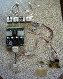
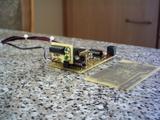
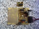
Last week I finished my electonic components.
I use a 4 axis TB 6560 driver board, with 4 Bi-directional Minebea 17 Stepper-motors.
I made a small modification on the driver board, I changed the 8 resistors for 0,8 amp phase.
For the heat controll I use a modified ver. from the BB2001. The two switches are for heat on/off and man/pc and
the poti is for manuall temp.. The timer for GMFC or Jedicut is also includet, but I can also use a external
timer modul for example with a NE555. I have all tested and all works ok with GMFC, Jedicut and Mach3.


Matthias
-
03-17-2010, 12:34 AM #6
Registered
- Join Date
- Mar 2010
- Posts
- 0
Matthias,
Thank you for the comments! That's a really neat project! how big is your cutter going to be? I just found some really nice angle irons I'm going to make into brackets. I have gone to a new design I will post probably this weekend for my x-axis. The brackets will be put on each side of 2 2X4 steel box beams running on either side of my X-axis screws. These brackets will rest in 2 slots that I can slide back and forth to gain parallelism between the 2 Axes. I'll show it in pictures this weekend I hope!
-Chris
-
03-17-2010, 03:30 PM #7
Registered
- Join Date
- Aug 2009
- Posts
- 11
Hi Chris,
my project looks like yours. I will a little bit edit this Fil_chaud_Morel.pdf
For my x axis I use a 2.10 x 1,14 x 0.12Inch Aluminium profile with two
mounts for 0.63 Inch linear waves.

The motor will mount from the backsite like yours.
I will make the X axis 37.40 Inch. Y is variable from 19.68 - 59 Inch I think. Z axis 24 Inch I think.
I will use slide bearings from this site
http://www.igus.de/iPro/iPro_02_0004....htm?c=DE&l=en
and this for the drive shafts
http://www.igus.de/wpck/default.aspx..._EFOM&CL=DE-de
Matthias

 Reply With Quote


Similar Threads
-
New design - Quick question about my design
By guerd87 in forum DIY CNC Router Table MachinesReplies: 1Last Post: 02-14-2010, 07:35 PM -
New Machine Design book from Alexander Slocum (of Precision Machine Design)
By toastydeath in forum Uncategorised MetalWorking MachinesReplies: 10Last Post: 11-25-2009, 05:37 PM -
design grad project: new breed of CNC design, need input
By nicanor76 in forum DIY CNC Router Table MachinesReplies: 11Last Post: 09-22-2009, 10:53 PM -
Finding Engineering Design Software For Automatic Machine Design
By hellokitty in forum Uncategorised CAM DiscussionReplies: 0Last Post: 01-06-2008, 07:39 AM -
Please help with CNC design
By nsiters in forum DIY CNC Router Table MachinesReplies: 3Last Post: 12-28-2006, 06:35 PM
