


Hi, my Honeywell hall switches arrived and I figured it might be good to start an open-source thread on using electronic hall switches for home sensors (or limit sensors).
Please contribute to the thread! Especially if you have any experience with electronic (contactless) sensors on your CNC machine, I've searched this forum a couple of times and there seems to be a lack of information on them.
Hall Effect Switches.
I chose the Honeywell SS441 sensor as it seems common enough and has some decent features. There is also a SS541 sensor, that seems to be the same device but in a surface mount package that requires a special PCB.
The SS441 is probably easier to use for most people as it has legs that are more easily soldered.
There are a few sensors in the range. The SS441 is "unipolar" meaning it just needs the presense of a magnetic field to operate. The "bipolar" sensors can detect if a magnetic field is North or South, which is not needed for limit switches.
The SS441 is suited for lower strength magnets, and is temperature compensated. It's temperature compensation matches that of lower strength (older style) magnets.
My initial testing showed that the new super magnets give a greater sensing distance from magnet to sensor, but this seems to reduce sensitivity as we need to detect a close precise distance. So unless testing proves otherwise it seems that older style low-power magnets are the best for this application.
Results 1 to 20 of 1243
Hybrid View
-
03-21-2010, 12:20 PM #1
 Registered
- Join Date
- Oct 2005
- Posts
- 2392
Electronic home switches made easy!
-
03-21-2010, 12:45 PM #2
Registered
- Join Date
- Oct 2005
- Posts
- 2392
Where to buy them;
I bought them from Farnell, they were $3 each in the catalogue but when I phoned to order they were only 78 cents each.
311-1477 Honeywell SS441A SENSOR, HALL EFFECT
Datasheets;
SS441 Datasheet;
Honeywell SS441 Hall Switch.pdf
SS541 (surface mount version) Datasheet;
Honeywell SS541 Hall Switch.pdf
How to test the sensor.
The SS441 and SS541 have 3 legs;
+ (+5v power)
- (0v ground)
O (Output)
The datasheet says 4v to 30v is ok for power, but I used +5v regulated as that is available on my CNC machine (and most machines) and using regulated voltage for the power eliminates one variable that might affect the sensing characteristics.
The easiest way to understand these sensors is to see the output like a switch to ground, whenever the magnet is present.
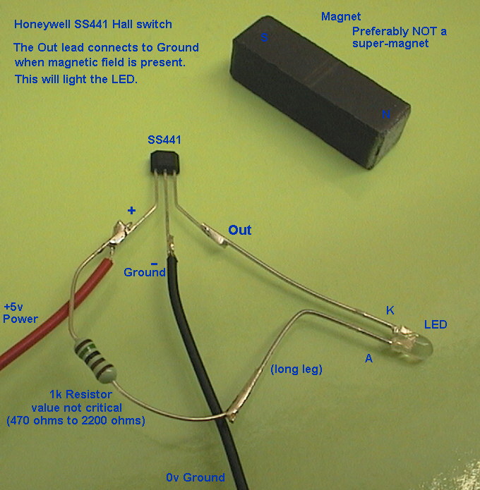
This is a very simple test rig that only needs a resistor and a LED. When the magnet is present the Output leg switches to ground and the LED lights up. The test rig took about 30 seconds to make, and was powered from +5v and ground via the Red and Black wires.
Test rig results
This worked well. I used a 1.5k (1500 ohm) resistor and a high brightness LED but the resistor value is not critical nor is the type of LED.
The sensing surface of the SS441 is the front (or back) face. When a magnetic South field is present near the front face it switches on (Output connects to ground). Likewise it switches on the same if a North field is near the back face of the device.
The front face has the writing and sloped sides. The back face is flat.
I tested a few magnet types and settled on 2 small bar magnets that operated the sensor from about 5mm (3/16"). Hysteresis was about 3mm (1.8") or less.
Hysteresis means that once the sensor turns on, the magnet must be withdrawn a certain distance for it to switch off again.
Using a lower strength magnet means the magnet must be closer to activate the sensor, and the hysteresis is much smaller, and the repeatability of the "on" trigger point is better as this is over a smaller physical distance.
-
03-21-2010, 12:58 PM #3
Registered
- Join Date
- Oct 2005
- Posts
- 2392
Mounting the sensors
If you have the smaller, surface-mount SS541 sensors they will need small PCB made, or some tricky soldering.
But I deliberately bought the SS441 to allow easy soldering. They can be soldered onto standard 0.1" stripboard ("veroboard" brand or similar) but in a pinch you could just solder the 3 wires to the 3 legs and secure the lot with a blob of epoxy.
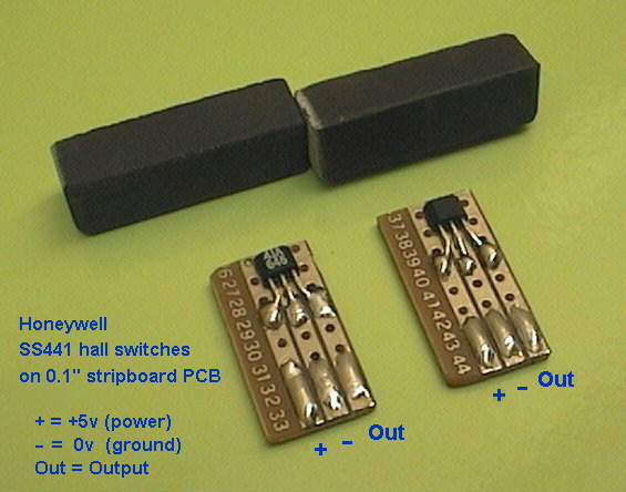
I cut 2 small pieces from 0.1" stripboard, leaving just 3 strips (to solder to 3 legs). The little PCB are about 10mm x 20mm (3/8" x 3/4").
When bending the legs make sure you bend them out AND down, so only the points at the end of the legs touch the PCB strips. This makes it easier to solder and has less chance of shorting between legs.
-
03-21-2010, 01:14 PM #4
Registered
- Join Date
- Oct 2005
- Posts
- 2392
First tests on the CNC machine
I glued the little sensor PCBs onto small pieces of plastic using non-acetic (non corrosive) silicone as the glue. This will allow testing but also allows for removal and repositioning if needed.
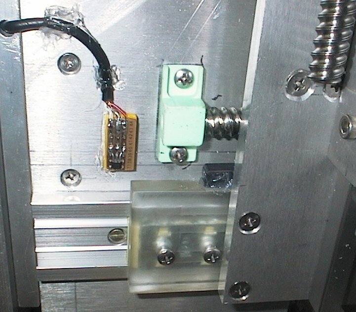
For the X axis I glued the magnet onto the moving part and the sensor PCB onto the gantry.
The end of the magnet just covers the face of the SS441 sensor when at the home position. There is about 2mm gap between. It triggers the sensor when approaching, about 10mm (3/8") before it reaches the home position, about 5mm between the end of the magnet and the edge of the SS441.
This will allow a safety margin of up to 10mm when moving home just in case it has skipped some steps in either way.
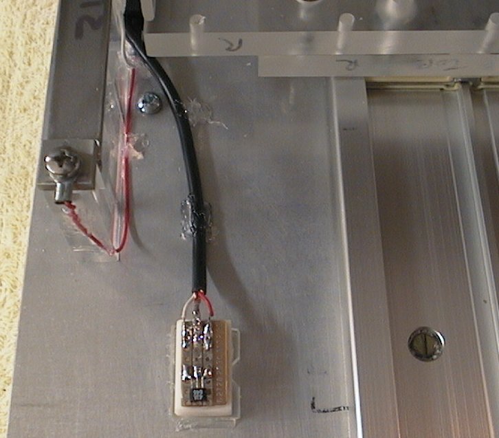
On the Y axis I glued the magnet onto the moving table, and the sensor PCB to the machine's base plate. The distances are similar to the X axis setup, it triggers the sensor when approaching, about 10mm before reaching home.
I'll let the silicone glue set a bit overnight and tomorrow I'll write some software to test the repeatability of both sensors with the machine moving home at different speeds.
-
03-22-2010, 12:45 AM #5
Gold Member
- Join Date
- Jun 2003
- Posts
- 2103
Roman I will be watching this thread. I only wish I had something to give to it, but alas.....electronics is not my strong point.
MikeNo greater love can a man have than this, that he give his life for a friend.
-
03-22-2010, 09:55 AM #6
Registered
- Join Date
- Oct 2005
- Posts
- 2392
Thanks for the interest guys!
Actually that makes your viewpoint very valuable to the thread! As an electronics guy I know roughly what info to provide to help electrical people use these sensors but I don't know how scary this looks to a person from a non-electrical background. I've been trying to explain it simply and would appreciate feedback on whether I am making sense and making the sensors seem easy to use, or if it seems too hard or I am explaining it badly etc. Originally Posted by turmite

-
08-23-2017, 07:21 PM #7
Registered
- Join Date
- Jan 2017
- Posts
- 9
Re: Electronic home switches made easy!
Hello Roman,
Could you please reply;
1) is the triggering done in position A or B on the sketch -
2) Can you indicate the distance in mm ?
3) how far beck you need to go to get out of Hall sensor to be in "Green" again ?
I am looking for solution on my Pick & Place where space is very limited....
Thanks
Mike
-
08-23-2017, 07:57 PM #8
Community Moderator
- Join Date
- Dec 2003
- Posts
- 24221
Re: Electronic home switches made easy!
Yes, he has been also absent from other forums he belonged to since around 2013, also his web site has not been updated since then. https://www.romanblack.com/ Originally Posted by Mike58
Al.CNC, Mechatronics Integration and Custom Machine Design
“Logic will get you from A to B. Imagination will take you everywhere.”
Albert E.
-
03-22-2010, 12:59 AM #9
Registered

- Join Date
- Feb 2009
- Posts
- 1290
Very nice write up.
For a inexpensive 5VDC power supply, I used an old cell phone AC Adaptor with my optical home switches.
-
03-22-2010, 11:01 AM #10
Registered
- Join Date
- Jan 2009
- Posts
- 72
Thanks for this thread Roman,
I am looking forward to understanding a little bit more about electronics
All Australian Politicians should serve two terms
One in Parliament
And one in jail
-
03-22-2010, 02:33 PM #11
Member
- Join Date
- Jan 2005
- Posts
- 15362
Hi RomanLini
This has been use before, but like you say not much imformation on them any were, that is because they have very limited use on metal cutting machine, they would be ok on wood working machines,were you only have wood dust to deal with
The magnets get covered with metal chip, so you know what happens next, & there's no way to stop this from happening
There are lots of machines that use proximity sensors ,but they don't use magnets as there trigger
You have done a great write up on this, that should help anybody that wants to try itMactec54
-
03-22-2010, 10:50 PM #12
Registered
- Join Date
- Oct 2009
- Posts
- 272
RomanLini,
I too will be watching this thread!
You have done a great job explaining/describing these sensors (even I understand your explanations). You made/make it seem as though even I could make these quite easily.
If I had an apple, I would give it to you for being such a good teacher (perhaps a cold one will do)! :cheers:
Randy,I may not be good....
But I am S L O W!!
-
04-27-2010, 04:24 PM #13
Registered
- Join Date
- Jun 2004
- Posts
- 35
Those switches are an excellent choice for being used as homming switches. Now with that being said let me point out that they shouldn't be used as overtravel switches because of the fact that the are sinking or "normally open" switches and not sourcing or "normally closed" switches. It is good practice to use a normally closed switch in an e-stop type of situation. In the even that you have a wire break the machine will shut down when using a normally closed switch. Thank you for the open source design it is in fact a great idea to use for homing a machine and keeping the tolerences closer:cheers:
Is the voice in my head bothering you?
-
02-05-2011, 03:24 AM #14
Junior Member

- Join Date
- Jun 2007
- Posts
- 31
Reed switch
Hello, I am not sure a reed switch works the same way as the switch in this thread. I am having problems with a switch that retracts the tool magazine in my machine. The switch is mounted outside the piston cylinder and when it activates the magazine retracts. Would it be a good idea to go DIY?
http://www.boschrexroth.com/pneumati..._p41066_en.pdf
This is the spec sheet for the part number. The machine I have is an Okuma ES-V3016
Thank you.
-
02-05-2011, 03:40 AM #15
Registered
- Join Date
- Dec 2009
- Posts
- 528
Reed sensors should work. I've played with the Hamlin reed sensor (see attached) and they work. The accuracy is as good as the hall effect sensor with the added benefit of not having to need a power source. Also, you can get them as Normally Closed vs the Normally Open switch for the hall effect sensor. Originally Posted by brujo
Not sure about effect of temperature but from the searches I've done, reed sensors don't seem to be affected by temperature.
-
02-05-2011, 02:25 PM #16
Registered
- Join Date
- Oct 2005
- Posts
- 2392
Originally Posted by jsantos
Reed switches will work as home and limit switches but I would never expect the accuracy you can get from the hall sensor.
The reed switch is mechanical and may be subject to contact wear and spring wear, also they are not temperature compensated and because they mechanically move to make a contact they perform differently with different changes in field strength over time, ie if your machine moves fast the reed switch will operate at a slightly different point than if the machine is moving slowly.
I agree their simplicity might make them attractive but really they are a big step down in performance. Considering that the hall switches are only a couple of dollars each (or less) and a few people have already posted DXF files of the mounts you can cut for free, I would really advise just going for the best right from the start.
Reed switches are better suited for simple applications like detecting when the burglar opens your door.
-
03-08-2012, 08:58 PM #17
Registered
- Join Date
- Dec 2010
- Posts
- 0
At the beginning of this topic (post9)
Originally Posted by RomanLini
My ideas about increasing homing accuracy is in the line from my question about putting Hall sensors in serial connection and the idea is simple: trigger on angular position.
Just as example:
- place on the spindle an disk with a magnet on a pitch diameter (Dp) of 40mm
- the thread on the spindle has a pitch (p) of 5mm
- the accuracy (acc) of the sensor is +/- 0.01mm
This means in one turn of the spindle:
- the axis has moved 5mm
- the traveling distance of the magnet inside the disk (Mt) is pi * Dp = 125mm
- the accuracy of the axis home position has become: acc * p / Mt = 0.01 / 25 = +/- 0.0004mm
To do this, place in travel direction a swicth (A) thats closes contacts just before homing position and powers up the Hall sensor. After a short time the Hall sensor should be operated and sets homing position. Before the spindle has made one turn, the contacts of switch (A) are opened to prevent from having more then one homing position.
Advantage of setting the homing position by this method is:
- increased accuracy
- the angular position of the spindle is not influenced by lineair expansion as a result of raising temperature.
- the sensor for angular position can easy build into a housing so its isolated from dirt, steel chips etc.
Regards, Leo
-
03-23-2010, 03:54 PM #18
Registered
- Join Date
- Oct 2005
- Posts
- 2392
That is a good point mactec54, these sensors are not very useful in a machine that will be cutting steel or ferrous metals. Originally Posted by mactec54
But I think they are ideal for router type machines cutting wood, plastic, aluminium. Even with the small chance of getting metal shaving stuck to the magnets (which would change the sense distances) they are still more accurate and reliable than any type of mechanical microswitch.
I want to make that point again that the best type of magnet for these sensors is a small one with a weak magnetic field, this gives closer sensing and better distance accuracy. Small weak magnets are also less likely to collect trash, and can be designed for easy cleaning as only one end of the magnet needs to be accessible to trigger the hall switch, the rest of the magnet can be buried inside a wood or plastic block.
-
03-23-2010, 04:26 PM #19
Registered
- Join Date
- Oct 2005
- Posts
- 2392
Making mounts for the hall switches
I know people don't want to go sticking sensors all over their machines with silicone (like my test setup above!) so this evening I put aside some hours to make some mounts out of clear acrylic (some scrap I had lying around).
I roughed out some simple designs that can be cut out easily from 10mm (3/8") acrylic and from 6mm (1/4") acrylic.
This mount above is 10mm, and has a deep pocket to hold the wiring, solder connections etc. There is also a shallow pocket of 2mm depth to hold the hall switch, to it is close to the surface and allows the magnet to come close to the hall switch.
One drawback is that it needs to have a small hole drilled to insert the wires, and a special height pocket for the hall switch so there are 3 heights to be cut. Another drawback is that it needs more epoxy to fill it, and people using 5-minute araldite would be better with a small pocket that needs less filler.
Above is my second design, I tried to simplify the mount to the simplest features possible. It is made from 6mm acrylic and only needs one height cut, for the shallow pocket and screw area are both cut about 2.5mm deep.
It only needs a small amount of filler epoxy, and is more compact in general. The down side is that it is fiddlier to solder the wires because it is smaller and it is not as sturdy as the 10mm mount.
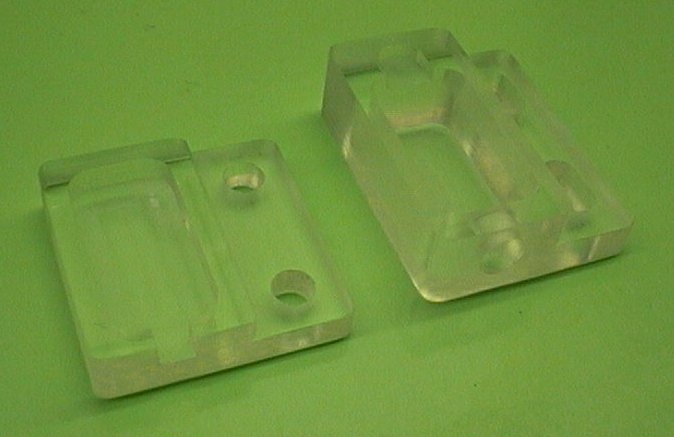
Above is a (fuzzy) photo of the 2 mounts, on the right the 10mm mount shows the hole drilled for the wires, and the deep pocket for the soldering, and uoi can just see the tiny shallow pocket for the hall switch.
On the left is the much simpler mount, with just one height cut for the pocket and screw recess. The wires are inserted by the simple slot.
Below shows that I made 3 of the smaller mount, because these are smaller than the 10mm mount I think they will be better for my small machine.
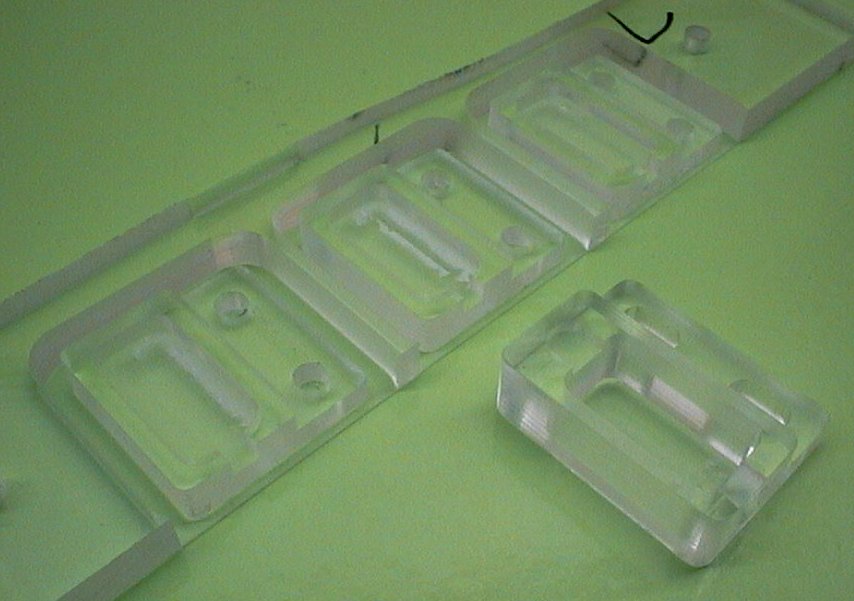
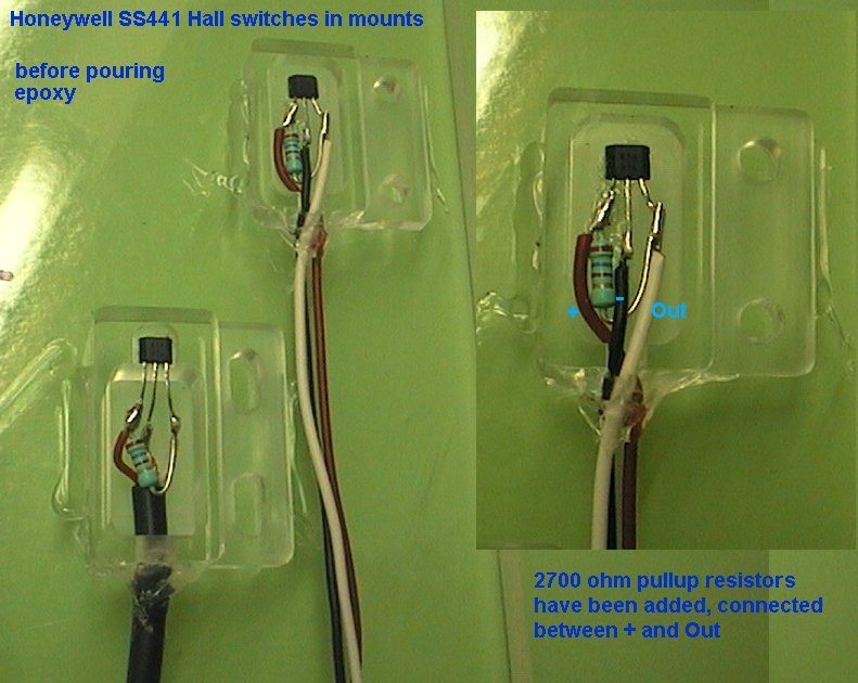
Next I soldered the wires to the hall switches and inserted them into the mounts. I added 2700 ohm resistors directly on the hall switches, there is room in the mounts to do this and it means I don't have to add resistors later.
The hall switches were quickly glued down with a little spot of superglue.
Then the wires were sealed with a hot melt glue gun so the epoxy won't leak out before it sets! You can also see where i glued the mounts onto a flat piece of plastic to hold them neat and level while pouring the epoxy. I put an extra glue blob on the wires too to hold them steady.
I used a shielded 2-core cable for the larger mount. This is cheap microphone cable, red+white+copper shield. It's quite tough, very flexible, and the shield is nice to have on longer cable runs.
On the small mount I used 3 wires, red, black and white. This will only have wires about a foot long so the shielding is not needed and was easier to solder in the confined space of the small pocket.
The epoxy is setting at the moment, i'll post photos of the finished mounts tomorrow.
-
03-23-2010, 07:33 PM #20
Registered
- Join Date
- Oct 2009
- Posts
- 272
Small (switches) Business Startup!
RomanLini,
Too bad, you already posted the instructions for these swithes. People would've had to buy them from you! I see people (all thumbs, like me) willing to buy them from you anyway. You should come up with a price and offer them for sale!
BTW, great job documenting the design and assembly!I may not be good....
But I am S L O W!!

 Reply With Quote
Similar Threads
-
Omni tech CNC 1212 does this machine have Limit switches and Home switches.
By zlswain in forum Chinese MachinesReplies: 3Last Post: 11-05-2013, 02:54 AM -
Home made electronic for Spindle control
By dinko in forum CNC Machine Related ElectronicsReplies: 1Last Post: 05-31-2012, 02:52 PM -
Auto backlash sensing with electronic home switches!
By RomanLini in forum Open Source CNC Machine DesignsReplies: 8Last Post: 11-14-2011, 02:36 PM -
The relationship of limit switches to home switches.
By MikeAber in forum CNC Machine Related ElectronicsReplies: 4Last Post: 11-04-2004, 08:28 PM -
Home made CNC mill (and some products made by it)
By gcamlibel in forum DIY CNC Router Table MachinesReplies: 23Last Post: 04-05-2004, 11:54 PM
