


I found this in a different post, I was just wondering if the grounding at the driver end meant connecting to pin 2/3/4 on the gecko in this 1st page of the diagram - or if it meant connecting to pin 12 as it is in the 2nd pageOriginally Posted by Crevice Reamer

http://www.kelinginc.net/G540WD.pdf
I am trying to figure out how to setup the home switches. I assume that I would use input 1-3. Any advice would be appreciated
Results 21 to 40 of 47
-
04-26-2010, 05:17 PM #21
 Registered
- Join Date
- Apr 2010
- Posts
- 0
-
04-26-2010, 06:53 PM #22
Registered
- Join Date
- Mar 2008
- Posts
- 3655
Yes! Connect the drain wire to one of the 2/3/4 pins. Insulate it with some heat-shrink tubing. You don't want that bare wire shorting against a motor terminal. Originally Posted by John V
Connect the home/limit switches NC and all in series. That way you will connect one end to input one and the other to ground, and leave your other inputs for future expansion. Mach3 knows when a switch is triggered, and whether it is a home or a limit.I am trying to figure out how to setup the home switches. I assume that I would use input 1-3. Any advice would be appreciated
CR.http://crevicereamer.com
Too many PMs. Email me to my name plus At A O L dot com.
-
04-27-2010, 01:12 AM #23
Registered
- Join Date
- Apr 2010
- Posts
- 0
First off... I am an idiot... I had bookmarked the gecko manual and glanced over it... needless to say it has all of my questions answered within the first page... So thanks for hanging in there and not (flame2)
After reading through it and seeing what has been said elsewhere I came up with this..
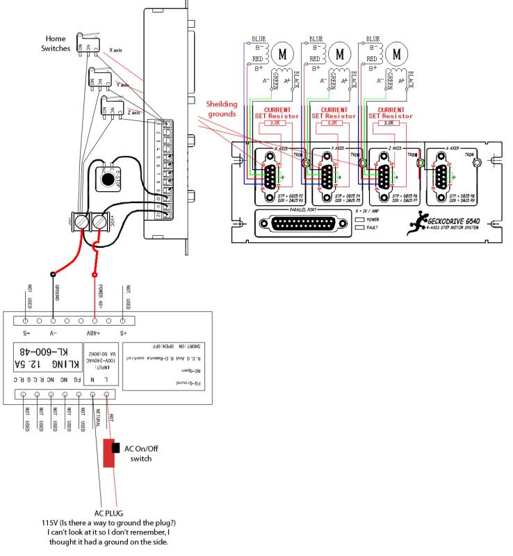
The 3.3K resistors are all that I have availiable right now without ordering anything and I would like to test it out on a board now. Before everything is put in a box with a fan I will change them to 3.48k's.
The ground for the plug is referring to using a 3 prong plug.
How do people usually wire a fan in the box with the Power supply and gecko board?
Feedback as always is appreciated. :cheers:
-
04-28-2010, 01:14 PM #24
Registered
- Join Date
- Apr 2010
- Posts
- 0
I found some other resisters so I'm going to run them at 3.47K..
Also any input on the electronics diagram? I think I'll be ok.. but I just want to make sure.
-
04-29-2010, 01:58 AM #25
Registered
- Join Date
- Dec 2009
- Posts
- 45
You have your home switches wired in parallel in your diagram. All three would have to open to change the pin 1 signal.
-
04-30-2010, 01:32 AM #26
Registered
- Join Date
- Apr 2010
- Posts
- 0
Man I'm making a fool of myself on here lol
:withstupi
Thanks. I don't know why I did that either.
Started machining Hoss's kit.
-
06-01-2010, 10:45 PM #27
Registered
- Join Date
- Apr 2010
- Posts
- 0
Just waiting on some of hoss's couplers then all of the assembly regarding the machine will be complete.
-
06-02-2010, 01:29 PM #28
Registered
- Join Date
- Oct 2009
- Posts
- 446
Im going to take a seat and enjoy your show . Please post as many pictures and details as possible,
Thank you
Anthony
-
06-09-2010, 02:20 AM #29
Registered
- Join Date
- Apr 2010
- Posts
- 0
Well this is where we are at today...

Still waiting on the shielded wire that was ordered last week, after its received everything can be wired up!
(you can see my driver box under the monitor, gotta love using old stuff that was sitting around in a buddies garage! Old junction box - Free, Emergency stop switch - Free, Powder coat at home - Free - I'm pleased with how it came out)
Just a side note the machine will not be ran as it is in the picture, I have an old drill press stand that will be used with a under tray and Plexiglas sides/doors.
-
06-12-2010, 12:52 AM #30
Registered
- Join Date
- Apr 2010
- Posts
- 0
Need help - stepper motors buzzing but no movement
I just found out today that my wire has not shipped, so I took some regular wire I had laying around - 4strand 1 cable, and hooked it up to the stepper motor and the 9pin connector for the gecko, along with the resistors.
I am using the settings as seen here for mach 3.
1. First you need to go to Config/Ports and Pins/ Motor Outputs and enable the axis' you want to configure, X Y and Z in this case.
2. Enter the Step (2 for gecko) Dir pin (3 for gecko)
3. Enter the Step Port and Dir Port #, This will be 1 for a single BOB or maybe 2 if you added a 2nd parallel port with a 2nd BOB.
4. The Step Low and Dir Low Active will vary from system to system. If the motor spins in the wrong direction, you can change the Dir Low Active checkbox later. If the motor doesn't spin at all at first, change the Step Low Active checkbox. Click Apply and close.
5. Go to Config/Motor Tuning. The Axis you enabled before will have buttons available in the Axis Selection. We'll setup the X, the rest will be the same just be sure to click
Save Axis Settings before moving to another Axis.
6. Enter the Steps Per #, This is the number of steps your system needs to pulse to get the axis to move 1 inch. For the KL-4030 using 1/2 step mode and ballscrews, enter 2000.
The motor moves 200 steps/per rev. 1/2 step mode microstepping pulses twice as many steps as full step mode, (1/8 microstepping pulses 8 times as many) the ballscrew is .200 pitch which is 5 Turns Per Inch (TPI). So 200 x 2 x 5 = 2000. If you are using a G540
enter 10000. It uses 1/10 microstepping.
7. Velocity is the IPM (Inch Per Minute) speed for the Axis. Start out using 100. Test the axis by using the jog buttons to rapid it from one end of travel to the other. If it runs smooth, doesn't stall and doesn't make a loud buzzing/grinding noise ( sign that it's missing steps) increase the number by 25 and repeat. Continue till you do hear the telltale noise, than back off to the previous setting. If you hear it at anypoint, the speed is too fast and you need to back off.
8. Acceleration varies the time it takes for the motor to get up to rapid speed.and slow back down. A very low number will have longer Acceleration/Deceleration rate. A higher number will start and stop the motor almost instantly. 5 is a good baseline.
9. Step and Dir Pulse are typically 1 and 0.
10. Repeat for the other Axis' making sure to Save Axis Setting each time and click OK
You should be ready to put power to your motors and use the Arrows and Page Up/Down
keyboard keys to jog the Axis'. Page up should move the Z axis up and the
Z DRO #'s goes positive, the Right Arrow should move the X axis to the left, the X DRO # goes positive and the Up Arrow moves the Y axis towards the front with the Y DRO # going positive.
The motor moves a tiny bit (Barely see the handle I made move a step,disconnected from the table) but does not move like it is healthy at all. It also is making a soft humming noise whenever power is applied. I assume that noise is normal.
What can/should I check?
Using 4wire 381in oz motors, 48V Keling power supply, G540, MACH3
Help would be appreciated!
Thanks
-
06-12-2010, 02:05 AM #31
Registered
- Join Date
- Sep 2006
- Posts
- 509
Does it rotate at all?
Sounds to me that it is likely one of 2 problems: either the motor is wired up wrong or you've got the step/dir wires crossed.
Double check your connections and try changing the step / direction wires 1st to see if that fixes it.
Mike
-
06-12-2010, 02:25 AM #32
Registered
- Join Date
- Apr 2010
- Posts
- 0
I am using this wiring diagram. http://www.kelinginc.net/G540WD.pdf Originally Posted by ninefinger
This is what gets me.. from the gecko initial setup - NOTE: If you have a motor wired incorrectly, the G540 will not exit FAULT mode. Connecting the
motors one at a time will help identifying which motor in particular is wired incorrectly if it enters FAULT
mode at this step.
Mine does not fault out....
-
06-12-2010, 06:59 PM #33
Registered
- Join Date
- Mar 2008
- Posts
- 3655
Hi John.
Open up your Db9 connectors one at a time. Check for any wires touching each other, loose or cold-soldered joints. Even a tiny stray strand of wire can cause problems.
CR.http://crevicereamer.com
Too many PMs. Email me to my name plus At A O L dot com.
-
06-12-2010, 07:09 PM #34
Registered
- Join Date
- Apr 2010
- Posts
- 0
I was just downstairs looking at it. I left the connectors open as I am still waiting for the other wire, however there are no wires touching, all are good connections. Originally Posted by Crevice Reamer
Should I hook up a different motor and see what it does?
I am using the 381in oz motors with 3.47k combined resistance (2 resistors) for the g540, see any problems there?
The wire to the motor is connected in one strand, and not shielded.. could this lead to an undesired effect of this magnitude? After reading on here I was under the impression it wouldn't be a problem..
Is there also a way to tell which version G540 you have easily? I looked on here last night and couldn't find any solid answers... My charge pump switch says on/off if that is a clue at all.
-
06-13-2010, 12:24 AM #35
Registered
- Join Date
- Mar 2008
- Posts
- 3655
Ordinary unshielded wire should be fine for motors. I assume you are using the UPPER diagram to wire the motors. Motors should lock up when power is applied. Where did you get your parallel cable? Have you verified that it is a "straight thru" type?
CR.http://crevicereamer.com
Too many PMs. Email me to my name plus At A O L dot com.
-
06-13-2010, 12:34 AM #36
Registered
- Join Date
- Apr 2010
- Posts
- 0
Ok, Yes that was the diagram I used. The upper with the motors going to the g540. Originally Posted by Crevice Reamer
It does lock up when power is applied.
Virtual PC's in town. Pin 1 ohm's out to Pin 1 on both ends of the cable, same with Pin 2 to Pin 2 etc.
I took a video of what the stepper motor is doing. I'll upload it shortly.
Link to the vid [nomedia="http://www.youtube.com/watch?v=7lY11jpzI6A"]YouTube- VID 00001-20100612-1932.3GP[/nomedia]
-
06-13-2010, 02:06 AM #37
Registered
- Join Date
- Apr 2010
- Posts
- 0
So I restarted the computer and re attached the 25pin cable and moved some of the wires around and now everything works....

I am glad everything works.. but still a little confused at what actually made it work.
-
06-13-2010, 05:18 PM #38
Registered
- Join Date
- Feb 2010
- Posts
- 0
a cold solder on one of the plugs will do it. I had the same issue, and after a full night of soldering realized that I did a not so great job the next morning. when you are talking about "jiggle the handle" gremlins there is usually a stray hair, or your wire is stripped too far out and able to lean over and touch ground. Sometimes a bad connector will send its neighbor (next channel over) into err mode.
Get a cheapo voltmeter with continuity check-hold one end on ground and move to each pin independently for each side and wiggle the cable/plug connection. It will be worth it when you figure out which cord it is. And will show up any other weaknesses elsewhere.
-
06-13-2010, 06:06 PM #39
Registered
- Join Date
- Mar 2008
- Posts
- 3655
Good advice Matt!
One of these would do the job:
http://www.harborfreight.com/7-funct...ter-90899.html
CR.http://crevicereamer.com
Too many PMs. Email me to my name plus At A O L dot com.
-
06-13-2010, 06:43 PM #40
Registered
- Join Date
- Apr 2010
- Posts
- 0
I got everything set up and working today.
I did end up redoing the first cable I did.
[nomedia="http://www.youtube.com/watch?v=wm4eLIwwj0U"]YouTube- VID 00004-20100613-1332.3GP[/nomedia]
Just gotta get the home switches in and will start attacking the list of projects for it!

 Reply With Quote
Similar Threads
-
Buying first Mill thoughts, Need feedback
By Seltzer Customs in forum Uncategorised MetalWorking MachinesReplies: 6Last Post: 11-21-2009, 11:28 PM -
New design idea - feedback appreciated
By lsteele in forum DIY CNC Router Table MachinesReplies: 0Last Post: 12-04-2008, 01:49 PM -
New Laser Engraver...Your thoughts and Feedback??
By velocitygraphix in forum Laser Engraving / Cutting Machine General TopicsReplies: 7Last Post: 10-30-2008, 01:12 PM -
Any advice appreciated - newbie
By TB300 in forum MetalWork DiscussionReplies: 1Last Post: 12-27-2007, 07:19 PM -
newbie question - help is appreciated
By tarsier in forum Commercial CNC Wood RoutersReplies: 3Last Post: 08-03-2007, 01:08 AM
