


I'm in the process of setting up everything in Mach3 still a little unclear on a few things and need conformation on others.
System: Mach3, C35 BOB, PS-KL-600-48 48V/12.5A, 5056D drivers, 570oz Steppers direct drive.
How should I set the dip switches on the 5056D drivers? Is UP on?
I powered the board off the 5v output from the PS. There are no warnings not to do this.
Mach3
Motor outputs- do I want Dir lowactive & step low active checked? BTW What does LOW mean?
I have ballscrews 5tpi and 0.200 in/rev for all 3 axis
Motor Tunning-What should I enter in all the boxes for reasonable performance? Where does 1/2 microstepping & 2000steps/" come in to play.
Thomas
Results 1 to 20 of 21
-
12-09-2011, 05:07 PM #1
 Registered
- Join Date
- Feb 2006
- Posts
- 44
C35, 5056D, Mach3 Setup Questions
-
12-09-2011, 06:27 PM #2
Registered

- Join Date
- Jul 2006
- Posts
- 887
you can power off of the 5v rail of the power supply.
If I remember right, up is off (towards the outside of the drive) there is an arrow and the word ON on the blue dip switch housing to tell you.
1Off 2on 3off is 10 microstepping if I remember right.
Attached is a picture of the non digital 5056 in one of my controllers.
Your motor tuning steps per will be dependant on the whole drive train. Motor steps per rev. 1.8 degree are 200 steps per rev. .9 degree are 400 steps per rev. on my systems with ball screws .9 degree steppers and 10 microstepping I run 800 steps per mm. the same setup with 1.8 steppers will be 400 steps per.
The silkscreen (I do believe) is the same dipswitch setting as the new digital ones, only on the old ones it tells you the microstepping.
I have a few of the 5056`s in some of my controllers. The non digital ones.
I also have 4 new digitals in a controller that I have not yet finished building.
-
12-09-2011, 06:39 PM #3
Member
- Join Date
- Apr 2006
- Posts
- 8159
I'll confirm that up is off, you can see the arrow in the pic showing which way the switches go for ON.
You can read about the high low thing here.
Step and Dir signals
Most times I leave my step low x'ed, I'll have to double check that but keling recommends step low active fwiw.
For your setup if you set the jumpers on the 5056d to 1/2 step (5 OFF, 6,7 and 8 ON)
you'll put 2000 in the steps per box.
Try a Velocity of 200 and and accel of 35 to start, you'll likely be able to go much higher on velocity.
Mine hit 525 on the X.
Good Luck,
Hosshttp://www.hossmachine.info - Gosh, you've... really got some nice toys here. - Roy Batty -- http://www.g0704.com - http://www.bf20.com - http://www.g0602.com
-
12-09-2011, 06:39 PM #4
Registered
- Join Date
- Jun 2011
- Posts
- 0
Unfortunately the answer is it depends on how you wire everything.
Last I looked at kellings diagrams, they are all designed for for active low.
Low active means that the signal lines are normally high (5V) and pulled down to indicate an "on" state.
In stepper drivers it means you measure the pulse width as the time from low to high rather than high to low.
-
12-09-2011, 08:32 PM #5
Registered
- Join Date
- Feb 2006
- Posts
- 44
Thanks for the help everyone. I already have the drivers mounted and apparently in such a way as to obscure the arrow. I'm looking forward to an evil laugh and yelling "It's ALIVE"
-
12-12-2011, 05:15 PM #6
Registered
- Join Date
- Feb 2006
- Posts
- 44
Still no evil laugh although there was some swearing. Still no movement.
When I turn on power to the PS and drivers I hear a faint thump on the axis motors.
Working backwards:
1) I have verified the dips are in the correct positon. Green lights across all drivers.
2) Inputs to drivers should be correct. Using c34 dapters that use cat5 cables to C35board. En+/Gnd pins at drivers have 2.5v at X&Y and for some reason 3.1v at Z. Voltage taken at BOB input not PS input (45v)
3) C34 dapters have pin jumper for hard or soft enable. I have it set for Hard. Tried both ways no change with respect to axis movement, only En+/gnd at Drvr input went to 0.5v with soft enable.
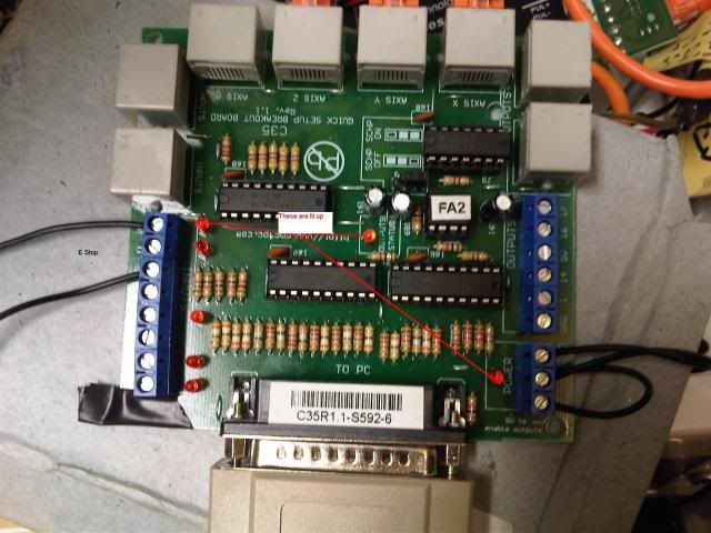
4) C35 BOB LEds lit at Estop, Pwr, & output status. I hit the estop and the led goes out at estop & output status.
5) Mach3 ver 3.043.037
1) port 378 verified, 25000hz checked
2) XYZ checked, dir low & step Low checked (tried both ways no change)
3) input estop port 1 pin 10 OK
4)Charge pump checked pin 17
Tried roadrunner g code and axis in mach were running.
How do I verify which pins on the input output screen match the BOB for the XYZ under the motor tab?
How do I verify that signal is going to and coming out of the BOB??
-
12-12-2011, 07:52 PM #7
Registered
- Join Date
- Nov 2009
- Posts
- 116
Do you have the common set to gnd or 5v? Should be 5v with those drivers I think.
I had this same problem and that's what fixed mine (I'm running C10 BOB though) - but otherwise my setup is very similar. (8056D drivers and 570 nema motors)
Good luck
-Doug
-
12-12-2011, 08:25 PM #8
Registered
- Join Date
- Jul 2006
- Posts
- 887
post up some pictures of how its wired.
Does the led on the break out board come on?
Do you also have the 5v going to each of the drives?
is the printer port a card or on board?
ECP mode?
verified the cabe is 1 to 1 pass thru?
can you use a jumper wire to one of the input pins as see a led light up in the diag screen?
estop setup? if you trigger the estop button do you get "Estop requested" in the status line?
-
12-13-2011, 12:10 AM #9
Registered
- Join Date
- Feb 2010
- Posts
- 114
Are you using the C34KLD or the C34KL ?
-
12-13-2011, 03:52 PM #10
Registered
- Join Date
- Feb 2006
- Posts
- 44
I have the C34KL, but on cnc4pc's website there is no difference in the 2. I talked to and sent pics to Arturo when I was originally hooking them up, because the wording was different between the driver & C34. He said it was fine and to just flip the board over and bend the pins to fit. Can anyone verify the difference in the C34kld & KL? I'm not sure about he common to 5v either. Is it in mach3 or does it not apply on the C35 BOB.
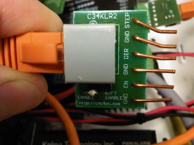
C34 flipped upside down so pins align. (note ignore dips position in pic I edited an old pic)
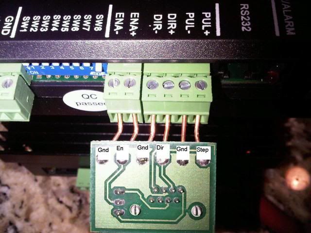
C35 BOB
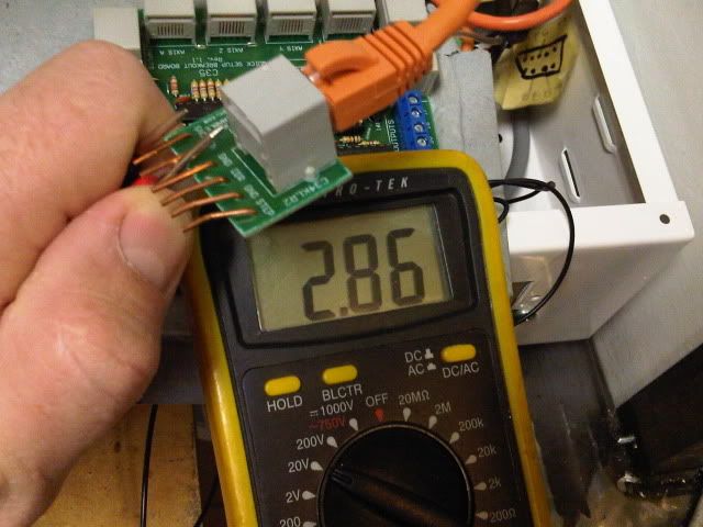
Voltage across EN/Gnd pins coming from BOB to Driver. Seems to vary between 2.5v & 3.1v and my meter has been having some issues internally, but it never goes above 3.1v.
-
12-13-2011, 04:42 PM #11
Registered
- Join Date
- Sep 2010
- Posts
- 46
To use the C34KL for my 8056D (very similar to 5056D (which I originally ordered but keiling upgraded me to 8056D for free since 5056D was back ordered.)I had to cut the end of CAT5 cable and remake an end switching two wires.
http://www.cnczone.com/forums/1009687-post52.html
I followed those directions and got my motors up and running in no time. If you dont have the CAT5 crimper tool you could always just strip the ends of the CAT5 cable and insert the bare wire ends to test things out.
The full thread that I found discussing this in great detail is located below the driver wiring discussion starts on page 2:
http://www.cnczone.com/forums/bencht...version-2.html
Also I didnt use the EN pins they end up not connecting to anything when you do this anyway as you flip the C34 upside down and it hangs the EN pins out in the air. (its in the link above)
-
12-13-2011, 06:32 PM #12
Registered
- Join Date
- Nov 2009
- Posts
- 116
Sorry...my board (C10) has a jumper to easily select this. According to the CNC4PC website and the manual for the C35 it says: Originally Posted by Thomasn

• The common terminal to pins 2-9 can be ground or +5vdc. In the RJ45 terminal, there are wires with GND or +5vdc to allow using drivers that require +5vdc or GND as a common.
I think this is what is going wrong with your setup - which is what was wrong with mine and EXTREMELY frustrating. Everything appears to work, even the voltages across the step and dir pins work as they should when you jog...but no motion on the motors. Mine was an oversight of the jumper.
Yours looks to be a bit harder to fix...
Check the voltage between gnd and PUL+ and DIR+ pins; that needs to be 5v. I'm guessing as yours is setup now you will not get 5v...probably zero.
Reading what ahaidet says sounds like that was the problem with the RJ connectors - have to get the 5v to the common.
Sorry your having a tough time with it...you'll be elated when your motors finally start turning!
-Doug
-
12-13-2011, 09:16 PM #13
Registered
- Join Date
- Feb 2010
- Posts
- 114
Here's a picture of the C34KLD

http://imageshack.us/photo/my-images/859/c34kld.jpg/
-
12-13-2011, 10:10 PM #14
Registered
- Join Date
- Feb 2006
- Posts
- 44
I think I have it now or at least an idea for a few mods. I will most likely abandon the C34's and clip the wires and insert them directly into the driver. I can always unhook them from the BOB end if I need to make changes down the road.
-
12-14-2011, 03:58 PM #15
Registered
- Join Date
- Feb 2006
- Posts
- 44
Still no Bueno. I did find that my PS was only putting out +/-3V instead of the 5v labled on it. So I cut and old usb cable and powered the 5V directly from the computer to the BOB. Now I get 5v to the drivers. In the C35 manual for RJ45-1 (x axis) pin 2 is P.P. pin 2. That corresponds to Step + (pul+ on Drvr) on the C34 board. Pin 6 is P.P. Pin 3 that corresponds to Dir+ (Dir+ Drvr) on the C34. Pin 4 is ground and pin 5 is enable +5v when I hook my meter to this I get -5v meaning the ground is actually +5v and the En pin 5 is actually ground. I get +5v when I connect the meter to Pin 4neg & 5pos and then when I connect Pin 4 neg & pin 7pos which the manual says pin 7 is not used. So I connected Pin 4 +5v to Pul+ and Pin 2 to Pul-, Pin 7 +5v to Dir+ and Pin 6 to Dir-. In Mach3 under motor outputs I set Pul to Pin2 and Dir to pin 6 hoping that those numbers acutally corespond to the appropriate pins. The more I diagnose and try different combinations the more F.U.B.A.R.'d I think I'm making the system. BTW when I hooked the driver up as above I do not get 5V across the Pul+ & Dir+ pins I get 0 because there is no ground involved. I get ~0.5v across the pul+ & pul- and the same with the Dir+/-. Should I be hooking the ground up to the ground on the driver so it completes the circuit? I can try that, but did not think about it till now. I reached a point last night I had to lay everything down and go fix a drink and call it quits for the night.
-
12-15-2011, 02:56 PM #16
Registered
- Join Date
- Feb 2006
- Posts
- 44
IT'S ALIVE :bat:
For the next guy who has this problem and runs into this thread.
Set pins in Mach3 to correspond to C35 Manual ie P.P. pin 2 (X axis) means puls 2 in mach3 under ports & pins /motor tab. Dir is 3 in the case of the x axis. If you have C34KL all you have to do is clip or pull out the EN & Gnd (just the one next to the EN) pins so they do not fit in the driver. Flip the board solder side up and insert in the driver.
All 3 axis bind at some point in travel so now to tear it all back down and fix that. Mechanical issues are cake so it shouldn't be long.
-
12-15-2011, 10:04 PM #17
Registered
- Join Date
- Feb 2010
- Posts
- 114
Good to hear Thomasn that you figured it out. My hardware from Kelng inc arrives sometime this evening and I was going to hook mine up on the table to help assist once all my components arrived.

.
-
01-02-2012, 02:09 AM #18
Registered
- Join Date
- Feb 2010
- Posts
- 114
What default settings did you start off or end up with on your X/Y/Z for Mach3?
-
01-03-2012, 08:48 PM #19
Registered
- Join Date
- Feb 2006
- Posts
- 44
If your referring to ports & pins tab under options. I'll have to check but I think it was: Originally Posted by Signal9
x 2 3
y 4 5
z 6 7
-
01-04-2012, 12:42 AM #20
Registered
- Join Date
- Feb 2010
- Posts
- 114
Actually I was looking for both dip switch settings on the 5056D you are using and the Steps/Velocity/acceleration ?
I have mine set for 200/500/35 sitting on my project table. They make a lot of racket when the motor stops and starts.

 Reply With Quote
Similar Threads
-
Keling 5056D, Keling C10 BOB and Mach3 problem.
By DrewSmith007 in forum Automation Technology ProductsReplies: 37Last Post: 04-27-2013, 06:21 PM -
Mach3/Gecko G540 setup questions
By mlabruyere in forum Gecko DrivesReplies: 7Last Post: 12-14-2009, 11:05 AM -
Mach3 and servo motors Setup Questions!!
By happytriger2000 in forum Servo Motors / DrivesReplies: 3Last Post: 09-01-2007, 05:59 AM -
More Mach3 Setup Questions
By bill south in forum Mach MillReplies: 2Last Post: 05-08-2006, 04:10 PM -
Mach3 setup
By mlaws1172 in forum Mach Plasma / LaserReplies: 6Last Post: 11-30-2005, 05:14 PM
