


I started the CNC conversion of my new Milling Machine in a rather random place, with a pneumatic drawbar. This was rather prompted by this thread:
http://www.cnczone.com/forums/showpo...37&postcount=1
In fact I started off posting in that thread (http://www.cnczone.com/forums/showpo...&postcount=124), but have now decided that I should start a new one, as I am not actually making a spindle, just the drawbar. The intention is a full CNC conversion running EMC2. (I have already done one machine, which is working as well as can be expected for the starting machine).
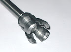
The drawbar fits in place of the standard drawbar with no modifications to the spindle. It uses a finger-style gripper:
From Gibbs
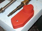
which is released by a specially-made pneumatic cylinder:
From Gibbs
and is held clamped tight by a stack of Belleville washers in the conventional way.
[nomedia="http://www.youtube.com/watch?v=pxrzJ_KfcQ0"]YouTube- Drawbar[/nomedia] shows the drawbar in action.
Results 1 to 20 of 35
Hybrid View
-
07-29-2010, 11:35 PM #1
 Member
- Join Date
- Sep 2008
- Posts
- 229
Harrison Universal Miller Conversion
-
07-30-2010, 08:57 AM #2
Gold Member
- Join Date
- Aug 2006
- Posts
- 1602
That is fantastic!

Very nicely mace, simple and even quiet in operation!
I'm really looking forward to seeing the rest of your conversion
-
08-04-2010, 11:02 PM #3
Member
- Join Date
- Sep 2008
- Posts
- 229
Sectional view of the solid model:
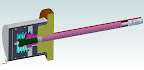
From Gibbs
-
08-05-2010, 02:20 AM #4
Registered

- Join Date
- Feb 2007
- Posts
- 592
 Question
Andy - is there any way you could show in that cut away view which parts rotate with the spindle and which are stationary. Some hatch lines or ??? Also is there any sort of bearing between rotating parts or just an air gap?
Looks great!
-
08-05-2010, 10:10 AM #5
Member
- Join Date
- Sep 2008
- Posts
- 229
I can describe it in words, if that helps?
The orange/brown part is the top of the milling head, comprising the bearing cap and the top of the rotating spindle. I didn't bother modelling it as separate parts as it didn't matter to me.
The red/pink parts and the dark green part all rotate with the spindle. As do the collet segments and the actuating rod.
The grey parts and the spring are stationary. There are no bearings, just an air gap of at least a couple of mm. It is intended that the spindle should always be stationary when the drawbar is released.
When air pressure is applied the piston moves down until a hardened steel plug (not shown) presses on the top of the drawbar central rod. Then the whole cylinder assembly floats upwards until the lower plate contacts the underside of the collar on the top of the drawbar, and then the drawbar is "squeezed" open.
I have seen many bits of advice that the spindle bearings are "not designed" to take axial loads so decided to use this "pinching" action.
As it happens, I am totally unconvinced about that "fact": The taper rollers in my spindle are rated for something like 50kN static axial load according to the manufacturers.
-
08-30-2010, 08:22 PM #6
Member
- Join Date
- Sep 2008
- Posts
- 229
Z-Axis
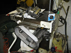
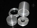
I found that steel (or Alu) blanks of sufficient size for the Z-drive conversion were quite expensive, so I decided to go for iron castings like the original machine builder did.
I made the patterns by gluing together 18mm MDF into blocks, then machining, hand-carving, filling, sanding etc. Then a couple of coats of spray-filler and red-oxide paint.
I then sent the patterns off to a foundry in Birmingham and the castings came back a week later, for £25 each.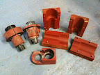
From Gibbs
From Gibbs
-
08-30-2010, 09:26 PM #7
Registered
- Join Date
- Feb 2007
- Posts
- 592
Wow, your lucky.
I have not been able to find a decent foundry that will do small lots in iron.
-
08-30-2010, 09:36 PM #8
Registered
- Join Date
- Jul 2003
- Posts
- 1754
andy: great work. We have looked at getting local castings and they don't seem too expensive.
what is your plan for cnc'ing the axis?
sam
-
08-30-2010, 10:17 PM #9
Member
- Join Date
- Sep 2008
- Posts
- 229
I am keeping the Acme screw (I think a ballscrew would need a brake, and I am sure the weight of the knee is more than any conceivable upwards cutting force). Originally Posted by samco

Currently the machine has a rotating screw and a static nut on top of of the machine base.
I am converting to a rotating nut in the same location, with the motor in the machine base rotating the screw through a drive tube coaxial with the screw. I will then fit a locking pin to the existing manual feed (and possibly one to the CNC axis too, to retain the possibility of manual drilling)
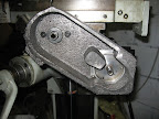
The casting that there are two of is a motor mount, it clamps round an extended bearing housing that pokes into the machine base. The motor fits into the part-circle on the top of the casting.
-
08-10-2011, 10:47 PM #10
Member
- Join Date
- Sep 2008
- Posts
- 229
It turned out that the leadscrew had too much friction for the motors with the weight of the table on there, so I converted to ballscrew:

From Gibbs
I am rather pleased with how the ballscrew-end machining came out:
From Gibbs
Installed in the machine it looks like this:
From Gibbs
With the motor and drive underneath (this is a rotating-nut arrangement)
From Gibbs
Having spent so much on the other parts, it seemed daft to not protect them, and as the original bellows was worn out, split, and the wrong shape, I spent £50 on a spring cover:
From Gibbs
-
08-10-2011, 10:53 PM #11
Registered
- Join Date
- Dec 2006
- Posts
- 839
Your pics are not coming through for me. BTW your work looks great. Be interesting tosee this machine working.
Jess
-
08-10-2011, 10:54 PM #12
Registered
- Join Date
- Dec 2006
- Posts
- 839
Well after posting the pics started showing.
Jess
-
08-10-2011, 11:52 PM #13
Member
- Join Date
- Sep 2008
- Posts
- 229
With the Z finished, time to start on Y.
Actually, Z isn't finished, I need to find a way to lock the Z at the top (I decided to retain manual Z for quick drilling jobs), but that is a job for another day.
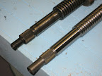
The ballscrew conversion of the Y axis was a bit of a challenge. The Acme leadscrew was originally screwed into the nut after the table was fitted. Not really an option with a ballscrew. However, due to assembly order constraints the screw has to be fitted with the knee mounted on the machine, so the ballscrew has to go in from the top, and can only be fractionally longer than the slot it lives in.
I needed a way to connect an extension to the ballscrew with good concentricity, no backlash and access only from one end, with very little radial clearance.
So, I stole an idea from the way that Wohlhaupter attach the shanks to their boring heads. A hex socket grubscrew/setscrew with two sections of different diameter and different thread pitch (actually, the diameters could be the same). You screw it all the way in, screw down the mating part, then back out the screw. The screw screws into the coarse threaded part faster than out of the fine-threaded part, and pulls them ever so tightly together.
I machined a 6 degree taper on the end of the end of the ballscrew (assuming that Stephen Morse had done his homework) and made a dual-threaded screw.
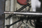
From Gibbs
Then it is a case of screwing the screw fully home, then screwing on the extension piece not-quite home (so that the screw pushes it off to release it in the future). Then the screw is backed out with an allen-key down the central bore, and it all snugs up tight, concentric and backlash-free.

From Gibbs
How likely am I to remember a few years down the line that that is how it works? Not very, I think, so perhaps a note taped to the inside of the cover is required.
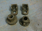
The last castings went well, but preparing the patterns in MDF was painful, it was too porous and hairy. So, I CNC routed the next pattern from a stack of glued plywood:
From Gibbs 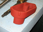
From Gibbs
Part-machined and test-fitted it looks like this:
From Gibbs
I was experimenting with knifing putty at that point, the surface finish of this casting was unimpressive, but for £30 it is hard to complain too loudly.
From Gibbs
-
10-04-2011, 01:20 PM #14
Registered
- Join Date
- Apr 2011
- Posts
- 0
andypugh
How did your conversion progress?
I purchased a Harrison mill with vertical head earlier this year and still looking for a manual. The machine is doing well.
___________
Danie
-
10-04-2011, 03:06 PM #15
Member
- Join Date
- Sep 2008
- Posts
- 229
The conversion is going slowly. I keep getting distracted by other vaguely-related things (like software drivers for IO cards) Originally Posted by Ratau
[QUOT]I purchased a Harrison mill with vertical head earlier this year and still looking for a manual.[/QUOTE]I bought a manual from eBay, it wasn't terribly expensive. Harrison Horizontal Milling Machine Manual | eBay
-
10-05-2011, 09:33 AM #16
Registered
- Join Date
- Apr 2011
- Posts
- 0
Thanks,
I will seek for the manual.
_________
Danie
-
12-22-2012, 12:57 AM #17
Member
- Join Date
- Sep 2008
- Posts
- 229
Two sorts of spindle feedback.
I am amazed that it is so long since I updated this thread, and equally amazed how little progress the actual machine has made in the last year.
This is partly because I spent a lot of time sailing (crossed the Pacific) and partly because I have been working on the software side of things.
So, an update. I have one axis working. But to get the other axes working with the drivers I have I need to update their firmware, and there is no Linux tool for that, so I am writing one.
I will post about that, with pictures and possibly video later.
The subject of this message is spindle feedback. It is handy for closed loop spindle-speed control (though I don't think spindle speeds have to be _that_ accurate). It is imperative for rigid tapping and gear hobbing though.
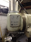
The Harrison Mill is a "Universal" mill, with a horizontal spindle and a vertical adapter. The mills came with two options of motor-to-gearbox pulleys and two vertical adapter ratios. With both fast ratios you have 100 to 2500 rpm. Guess which ratios I have? I have 47 rpm in the lowest gear, and 1000rpm in the highest. The VFD lets me boost that a bit.
In the long term I hope to make a pair of the high-speed vertical gears. You simply swap a 51:51 set for a 36:66 set inside the head rotate housing. However, that means that the spindle feedback needs to be in the head.
I decided to use some Allegro ATS667 devices running off the gears in the head:

From CNC-unsorted
These are (as far as I can tell) unique sensors that contain a magnet and a Hall device, and can detect anything magnetic with logic output.
Allegro MicroSystems - ATS667LSG: True Zero-Speed, High Accuracy Gear Tooth Sensor IC
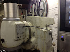
I bought some from eBay as I could not find a UK stockist. Then I mounted them in a bracket on the head cover:

From CNC-unsorted
The one at the bottom is for the index, it picks up off of a screw I put in a handy tapped hole on the spindle.
Because the sensors are running in oil, I needed an oiltight connector. Lemo connectors are lovely things, and vacuum-tight, so I used one of them.
From CNC-unsorted
Hang the expense!
From CNC-unsorted
It works very nicely, and I have spindle speed feedback and an interlock which prevents the pneumatic drawbar activating when the spindle is spinning.
-
12-22-2012, 01:55 AM #18
Member
- Join Date
- Sep 2008
- Posts
- 229
My axis motors came from ebay. They are fairly nice Lenze motors, and at £50 for three of them seemed a bargain. That special sort of bargain that then makes you decide to buy a decent base machine to use them on…
One slightly awkward thing about these motors is that they have Resolver feedback. Resolvers are lovely things. Tough, accurate, reliable and noise-resistant (even if they glitch, the position is correct next time. An incremental encoder keeps a false-count until it powers down.)
What Resolvers aren't is easy to interface to a PC. They are analogue devices. Worse still they are high-frequency AC analogue devices. I made a converter to read the three resolvers and output quadrature pulses using an Arduino: LinuxCNC Documentation Wiki: ResolverToQuadratureConverter But that seemed to throw away a useful feature of the Resolvers (they are absolute) so I set up a 1Mbps serial link from the Arduino to my Mesa 5i23 to send absolute positions.
One of the things that I did while not converting this machine was to write a driver for the Mesa 7i49 6-Resolver interface card, nothing to do with me) even though I wasn't using it. The Mesa card reports angles to 24 bit resolution, my Arduino thing was precise to 10 bits and accurate to 8 bits. When something went wrong with it, I didn't bother trying to find out what it was, I just bought a Mesa 7i49. (Curiously I managed to write the driver without ever seeing the actual hardware).
I do wish I had used a 7i49 from the start (not that that was possible, as it didn't exist then). It's just so much better. Suddenly the motors (which are brushless and use the Resolver for commutation) are smoother and easy to control.
The switch to Resolver feedback did have one drawback. Suddenly I had no encoder counters to connect the spindle to[1].
So, I now needed Resolver feedback on the spindle. Luckily a chap on the LinuxCNC list had a couple going spare after a conversion. He even sent them to me for free. Clint Washburn, you are a truly nice chap.
There really is no easy way to mount a resolver in or on the vertical head. But after some thought I decided that I only really want the feedback for gear hobbing, and I am likely to do that in the horizontal spindle. The rear-end of the horizontal spindle is easily accessible. I was going to use a belt drive, but noticed that that would be unusual for a resolver, and likely to apply belt tension loads that they are not designed for. It then occurred to me that if I used a gear drive then it could be a miniature version of the vertical head gearing, and that a 51:51 and 36:66 0.8 mod gear set would both fit, and run at the same centres, and so I could simply swap gears if I ever changed between ratios.
It didn't take long to find that 51T and 66T 0.8mod gears are not off-the-shelf items, but that's OK, I can already make gears:
[ame=http://www.youtube.com/watch?v=ZhICrb0Tbn4]Hobbing (Gear cutting) on a Mini-Mill with EMC2 - YouTube[/ame]
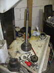
I decided to use Delrin, and made both the 51:51 and 66:36 set:

From CNC-unsorted
The 66 tooth gear, as the eagle-eyed might have noticed, demonstrates what you get if you make a 66 tooth gear with the dividing ratio at 12… But I decided to finish it anyway. It has zero addendum, but still seems to work. I will worry about making a better one if and when I swap the vertical head ratios.
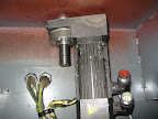
I then just needed to machine a register on the spindle rear bearing locknut, make a clearance slot in the existing rear cover, and mount the Resolver:
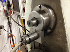
From CNC-unsorted
I wish I had a roundover bit, that bracket is ugly.
In this photo you can see the gear engaging with the spindle:
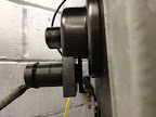
From CNC-unsorted
Tomorrow I might go to the optician, I thought I had deburred that gear.
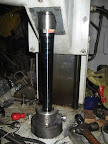
Next job, the X-axis drive. I fancy a static ballscrew so that the wires are not dangling in the breeze: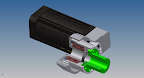
From CNC-unsorted
This design rather commits me to making my own T5 belt pulleys. Luckily I have spindle position feedback now, so I can hob them.
[1] This is only partly true, My setup is a D510MO Intel motherboard with a Mesa 7i43 board, connected to a 7i44 which connects to the three 8i20 drives, and the 7i64 which handles all the GPIO. Then the Resolver feedback is handles by the 7i49 card which also controls the spindle VFD, and then there is a 7i39 board to drive the rotary axes. This has quadrature encoder counters, but they are taken…
-
12-24-2012, 03:13 AM #19
Registered
- Join Date
- Apr 2007
- Posts
- 521
Super. Thanks.
-
08-03-2013, 01:06 AM #20
Member
- Join Date
- Sep 2008
- Posts
- 229
It's been a long time, largely because I found lots of other interesting projects along the way. But I now have 4 CNC axes on my Harrison Universal and a setup which lets me hob gears too.
This video shows it going through its paces:
http://=http://www.youtube.com/watch...QFvOublovDYoTQ
Other videos in the same gallery show it hobbing a timing pulley and a gear pinion.
Photos of the build process are in this gallery:
https://plus.google.com/photos/10816...88686374813281
I am more than happy to loan the patterns to anyone else wanting to do the same conversion.
Any questions?

 Reply With Quote
Similar Threads
-
Harrison 280 CNC interface
By Rufan in forum DNC Problems and SolutionsReplies: 0Last Post: 11-02-2011, 09:03 AM -
Harrison 600 Universal Miller info
By Ratau in forum Uncategorised MetalWorking MachinesReplies: 2Last Post: 05-15-2011, 01:00 PM -
harrison vs450
By evo123 in forum Uncategorised MetalWorking MachinesReplies: 0Last Post: 11-09-2009, 03:51 PM -
Harrison Lathe
By bugzpulverizer in forum CNC (Mill / Lathe) Control Software (NC)Replies: 2Last Post: 05-19-2009, 11:01 AM -
Harrison Alpha 400 HELP!!!!!
By themachinest in forum Community Club HouseReplies: 4Last Post: 02-26-2009, 05:44 PM
