


If you are concerned, add a 2-3 amp fuse. It will protect the motors.Originally Posted by pudzian

Do not use the series configuration. Use parallel. Moving torque is more useful than holding torque.
Results 661 to 680 of 900
-
01-23-2013, 01:47 AM #661
 Gold Member
- Join Date
- Jan 2005
- Posts
- 1695
-
01-24-2013, 12:30 PM #662
Registered
- Join Date
- Nov 2012
- Posts
- 0
Thanks for the advice. I could find any fuse at home so took a shot and tried to assemble averything. Nothing worked and since I never had a working system I'm not sure of what may be wrong. Originally Posted by H500
This is my setup:
Desktop:
Intel e2140
2 GB RAM
160GB SATA
PCI controller with a Parallel port LCS-6019 configured as EPP+ECP in BIOS
Steppers and Driver:
3 Axis TB6560AHQ without any mod yet
3 NEMA 23 3.1Nm Steppers ( http://cnc4you.co.uk/resources/60BYGH301B.PDF )
12v 20A Power supply
I'm using these stepper motors as Bipolar series which according to the documentation will draw 2.1A and because of these I have configured the DIP switches like this:

1 AND 5 OFF and all of the others ON. 1OFF | 2ON is supposed to give me 50% of current = 1.5A. This is not the 2.1A of the documentation but I was afraid of using the 75% which is equivalent to 2.25A, 1.15A over the limit.
I know the power supply is weak, but I'm still waiting for my 24v power supply to arrive. In the meantime this should be enough just to see the steppers moving :-(
The first thing I did was to download the linuxcnc live CD and run it. The configurations I downloaded from the linuxcnc wiki ( LinuxCNC Documentation Wiki: TB6560 ). I then connected the driver to the PC WITHOUT any stepper motor just to see if I could see the access leds blinking while moving the axis.
The first thing it happens is that three leds lights up as soon as I connect the parallel cable to the PC and turn the power supply on. If I connect the driver without the power power supply and just the parallel cable the same three lights turn on dimly. When I connect the power supply they get very bright.
Without the PS on:

With the PS on:

I loaded a G code sample and started the operation and nothing happened :|
The multimeter confirmed that no voltage was geting to the A+-/B+- of any pin axis. Because I wasn't sure that the parallel port was correctly detected and configure under linux (even though I had the /dev/lp0 and /dev/lp1 available).
Then I installed Windows XP Home 32bits and MACH3. The LPT port is correctly detected but I had the same problems: No activity leds blinking :-(
I then decided to take the risk and connect a stepper motor. The Z and Y axis are dead, but the X axis shows 6 volts between A+ and A- without any command sent from the MACH3. The stepper does some noise when connected and it looks like static noise.
The computer, parallel controller, steppers, driver and PSU are all brand new so I have no idea on how to troubleshoot this system.
Is there any way of testing all of the elements separately?
-
01-25-2013, 12:51 AM #663
Gold Member
- Join Date
- Jan 2005
- Posts
- 1695
I'm not really familiar with the board, but be sure you assert the enable pin, or there will be no motion.
-
01-26-2013, 09:24 AM #664
Registered
- Join Date
- Sep 2012
- Posts
- 0
You may have fried your driver chips. You should never power up the board without the motors connected.
-
01-27-2013, 11:07 AM #665
Registered
- Join Date
- Nov 2012
- Posts
- 0
Hi, Originally Posted by Dirty Steve
After all that I've read here I thought that the only thing I shouldn't do is to connect the steppers to the driver if the driver is already powered on.
Anyway I've found out that the problem was due to a damaged 74hc14 and a problem with the parallel port.
I was using a PCI parallel port that for some reason cannot have the legacy I/O addresses assigned. I tried the DOS configuration tool nmdosin.exe, but the settings keep beeing reseted after rebooting the computer.
I'm going to try to find another PCI Parallel controller or switch computer.
-
01-28-2013, 10:30 PM #666
Registered
- Join Date
- Dec 2012
- Posts
- 8
The jumpers you show will probably not work for the enable lines. On a 3-axis board they need to go straight across rather than diagonal. see circuit on second page of thread. Originally Posted by pudzian
You can leave the optos in for the enable lines if you like. This will make the mod simpler.
Else it looks good. the 10k resistor removal will lower your noise. I suggest trying each mod one at a time.
-
01-28-2013, 10:34 PM #667
Registered
- Join Date
- Dec 2012
- Posts
- 8
I suggest using this technique to check if your port and parallel cable are working properly. You only need a multimeter and trial of mach3. Originally Posted by pudzian
[ame=http://www.youtube.com/watch?v=uglCm_qsojk]CNC Electronics 5 -Testing the Parellel Port.wmv - YouTube[/ame]
-
01-29-2013, 12:01 AM #668
Gold Member
- Join Date
- Jan 2005
- Posts
- 1695
That will not harm the drivers. I do it on a semi-permanent basis. Originally Posted by Dirty Steve
-
01-29-2013, 06:04 AM #669
Registered
- Join Date
- Sep 2012
- Posts
- 0
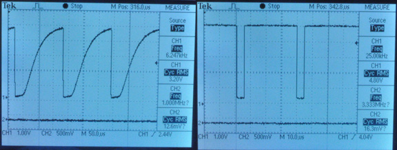
Is there any modification that can help smooth out higher feedrates? I've jumpered the step optos, removed resistors, and replaced timing caps. All these helped. Haven't tried jumpering all optos.
I get a jittering from my steppers at higher speeds requardless of microsteps, or current setting percentage. This creates a vertical pattern in my pieces, not relative to part geometry, also has jitter pattern in straight X or Y passes. Less pronounced at lower speeds, very faint pattern at 5mm/s.
1.8 degree motors, almost seems like the motor higher torques or 'snaps' into magnetic alignment as it passes each tooth of the rotor.
Running constant velocity Mach3, going to test LinuxCNC tomorrow.
-
01-29-2013, 12:10 PM #670
Registered
- Join Date
- Nov 2012
- Posts
- 0
Hello Neon22, Originally Posted by Neon22
Thanks for your response.
I've managed to get the PCI parallel port to work. It was a driver related problem and now everything works, but I think it is extremely slow!
I tried to use a jumper wire between pin 2 and 4 of each optos without success (nothing happens). I tried to search the schematics to remove the optos on 2nd page as you said but couldn't find anything.
I could find though, another post that is sugesting the same thing I did:
This time I'm just going to jumper those three optocouplers and see what happens. Originally Posted by Karl_Williams
Anyway, I have another issues ...
I bought a 24v 15A but while it doesn't arrive I'm using the 12v rail from an ATX PSU to test the steppers. Also, since I cannot use the steppers in bipolar parallel mode because it would draw 4.2A each I'm using them in bipolar series mode.
But the tb6560 settings don't allow me to go near the 2.1A. 25, 50, 75 and 100% are 0.75A, 1.5A, 2.25A and 3A respectively (I'm using the 3A as MAX current to calculate the percentages, not the 3.5A peak, is this correct?) so I'm using the 1.5A setting which is far below the required 2.1A? Could this be the problem?
I've seen people that replaced a resistor from the dip switches to use a right amount of current for their steppers, could someone do the same thing for me?
Just one more question: If I used the 2.25A setting would this kill the steppers?
Thanks!
-
01-29-2013, 05:15 PM #671
Registered
- Join Date
- May 2005
- Posts
- 1397
Get a decient stepper motor driver? Originally Posted by Dirty Steve
James hosts the single best wiki page about steppers for CNC hobbyists on the net:
http://www.piclist.com/techref/io/steppers.htm Disagree? Tell him what's missing! ,o)
-
01-30-2013, 12:56 AM #672
Gold Member
- Join Date
- Jan 2005
- Posts
- 1695
The old round motors are not really made for microstepping. The steps tend to be uneven. However, I would not expect it to be as noticeable at high speeds. Do you have a video? Originally Posted by Dirty Steve
-
01-30-2013, 01:21 AM #673
Gold Member
- Join Date
- Jan 2005
- Posts
- 1695
Bipolar parallel will not draw 4.2A. It would draw whatever your drive is set to. Originally Posted by pudzian
Bipolar series with a 24v supply is a capital crime. If your motor inductance is greater than 1 mH, don't use it unless you enjoy watching your machine stall at low speeds.
-
01-30-2013, 12:09 PM #674
Registered
- Join Date
- Nov 2012
- Posts
- 0
Originally Posted by H500
You are absolutely right. I have no idea why I wrote that since I knew that that is probably the main funtion of the driver: chopping current.
About the bipolar series, I wired them that way because I was expecting to configure the driver to give the exact 2.1A that the steppers need using that configuration but since I can't (I have no idea of which resistors to replace to provide this axact current value and therefor I'm using them with a 1.5A configuration) I'm going to set them up to bipolar parallel and set the driver to the maximum 3A (3.5 peak).
-
02-02-2013, 08:28 PM #675
Registered
- Join Date
- Jan 2013
- Posts
- 27
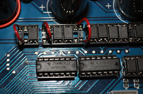
did you see a big improvement on the board when using the 74hc? i replaced my caps with 100pf and grounded my heatsink screws and noticed a HUGE difference in noise.I also removed the fan plug and wired it directly to the 12v psu. i removed the resistsors but steppers didnt like it at all.
I have some 74hc chips but i also have a new board and its a little different so i havent added the chip yet because i cant tell which lines to add the wires to.
I have the 3 axis board and apparently everything is different except for the cap mod.
I would also like to jump the isolators but there is some confusion on which way to jump them on the 3 axis boards(diagonally or straight up) so if anyone could clarify that would be great.
-
02-02-2013, 10:12 PM #676
Registered
- Join Date
- Jun 2011
- Posts
- 0
i have a few questions for the guys running these drivers.
i purchased(traded) for a 3 axis and 4 axis board. the dip switches i was told were set to properly run my motors(1-4 on, 5-6 off) and i was told not to mess with them. i am running a spectralight/sherline machine with the original round motors(see pic). i plan on running 24v 15a psu. but i believe the driver i got with the machines was only 12v(burned up driver when recieved) is this going to damage these motors? i was told no but i am just checking my source. i had to replace two can type capacitors on the 3 axis, one was leaking and another was installed backwards and bulged. i have not done any modifications apart from adding on leads to the input plug. what should i do to get this running correctly and reliably? i am currently getting ready to run with the 3 axis board.
pics of both boards when i received them and a pic of one of my mills is attached.
thanks.
Kevin.
-
02-02-2013, 10:31 PM #677
Registered
- Join Date
- Nov 2012
- Posts
- 0
The 100pf mod DID make a huge difference. Before that I could only run the steppers up to 240mm/m and after that I can use them with twice the previous velocity. Originally Posted by sharpen047
I also tried to remove the optoinsolators but using a jumper wire between the 2nd and 4th pin of each one of them didn't improve the results. I still need to remove the current resistor but I'm not sure of which resistor is because I have several 10k resistors on the board.
My steppers are rated for 4.2A but right now they are starving because this driver only gives them 3.0 at most. Anyway, at 12v I can use them at 600mm/m without problems. Not much I know, but still a big improvement. :-)
-
02-03-2013, 01:38 AM #678
Registered
- Join Date
- Jan 2013
- Posts
- 27
Now we need to find out how to incorporate the chip mod and see what happens. im stuck at 15.2 in/m or 386mm/m before i start losing steps. but that my be the power supply and i have current set pretty low. Originally Posted by pudzian
-
02-06-2013, 02:56 AM #679
Registered
- Join Date
- Jan 2013
- Posts
- 27
Ok just finished installing the 74HC14 and what an amazing difference!!! im at 24 ipm 1/16 with no missed steps! would like to know which way to jump the isos though on the 3 axis board.
Thanks everyone!
-
02-06-2013, 03:57 AM #680
Registered
- Join Date
- Jan 2013
- Posts
- 27
Ok just finished installing the 74HC14 and what an amazing difference!!! im at 24 ipm 1/16 with no missed steps! would like to know which way to jump the isos though on the 3 axis board.
Thanks everyone!

 Reply With Quote

Similar Threads
-
Chinese 3 Axis TB6560 & 300oz @ 24V too slow and not enough power
By KallDall in forum Stepper Motors / DrivesReplies: 12Last Post: 09-28-2016, 06:20 PM -
New (red version) of TB6560 chinese driver board
By hspalm in forum Stepper Motors / DrivesReplies: 19Last Post: 02-23-2014, 01:34 AM -
soc-robotics MK4cp OR chinese TB6560 driver
By 24ariel3 in forum Stepper Motors / DrivesReplies: 2Last Post: 04-09-2013, 04:24 AM -
Maximum Voltage with Chinese TB6560
By riphet in forum Stepper Motors / DrivesReplies: 9Last Post: 10-16-2012, 05:29 AM -
Just got my updated super Pid controller
By msimpson99 in forum DIY CNC Router Table MachinesReplies: 13Last Post: 12-22-2010, 10:35 AM
