


I've been lurking here for several years just reading the and soaking up the amazing amount of information that is available here. I've been dreaming of owning a plasma table for the past several years but the cost of a turnkey setup put it far out of reach. Thus I began researching the process to build my own. I looked at alot of different designs and companies for ideas. I had planned to start a small 4x4build months ago but, I landed a new job with a good amount of overtime so time has been rare lately.
I almost picked up a torchmate 2x2 for the ease of use but after further research I decided it would be more of a hassle than its worth. After reading many post from people saying they wished they had gone bigger I decided that I would learn from their mistakes and do it right the first time. I began talking to ron from perscion plasma and after his great responses and quick replies I took the plunge on a friday, wednesday I had my kit.
Here's the plans
Perscion plasma 5x10 kit
6" Rotary chuck
BladeRunner Aio 5 axis w/ 620 oz in motors
Hypertherm Powermax 45
Table built from 1/4" wall material
Custom Plate marker
Custom Pc w/ soildworks 2010
Cable track system
E stop Switch on either end of the table
Overhead gantry with lift magnet
Aircell refrigerated dryer
Plasmaspider 2 stage air dryer
I've got most of it figured out. I just need to save for the CandCNC setup and iron out a few details. I've been looking for cable track for a while now and think ive settled on the right type. Its from Igus series 25.4.100( 3x1(bend radius 3.5") I figure i'll need roughly 20" feet. Can any one give their opinion as to if this will work or is it too big? The price is right at bout $12/ft but after looking at many designs it seems its a little large in comparison. Can't wait to start on this!
Thanks,
Cory
Thread: Lonestar 5 x 10 Build
Results 1 to 20 of 29
-
09-04-2010, 01:10 AM #1
 Registered
- Join Date
- Sep 2010
- Posts
- 0
 Lonestar 5 x 10 Build
-
09-04-2010, 02:25 AM #2
Registered
- Join Date
- Jun 2010
- Posts
- 88
Sounds lie you have the plan figured out pretty well..
I ended up getting my Cable track from McMaster Carr.
Here is a link to my build using everything you are except I am only going 3x4 in size. My gantry also is from RON, great guy to deal with. Also my electronics all from Tom at CandCNC.
http://www.cnczone.com/forums/showthread.php?t=110827
Here is some info on my Cable track and for hole spacing on Precision Plasma's rail
Also for those using the presicion plasma gantry kit( non bolt together..)
Hole spacing on the rails is 3.15 or 80mm total holes for the 3x4 kit is 15 per rail.
Hole diameter .35
Also thank you to unixadm for giving me the Part numbers he used for the Cable track
I ordered 2-6 foot pcs and will make them fit my use.
1 4409T513 2 Each Open Hinged Cable And Hose Carrier, 0.98"h X 1.50"w Interior Size,2.17"bend Radius,6'l
2 4556T562 2 Pairs Mounting Bracket For Cable And Hose Carrier, Open, For 0.98"h X 1.50"w
-
09-29-2010, 05:54 PM #3
Registered
- Join Date
- Sep 2010
- Posts
- 0
Thanks for the info rock4x. I ended up picking up a few sections of igus cable track on eBay so ill make those work. BTW get well soon and back to your new table.
Well I've finally saved enough to order the controls and software from candcnc.com. I was curious as to if any one had any thoughts as to maybe any upgrades or added features that I should include when I place my order that others may have wished they would of included after putting the system into service.
Thanks
Cory
-
10-04-2010, 12:15 AM #4
Registered
- Join Date
- Sep 2010
- Posts
- 0
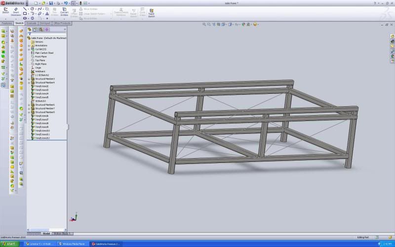
Heres the final design for the table. All the controls and software were ordered form candcnc.com Thursday afternoon. I'll make a cut list this evening so that I can get a total quantity of steel needed to make an order Monday.
Main structure 3x3x.250
supports and bracing 2x2.250 and 2x2x.125
Pc/controls/plasma cutter enclosure water tank and water table 16 gague
The table is a twist on the original design for Ron at precision plasma. I designed the water pan with a 1/4 slope every foot and a drain in the middle to assist with drainage. I plan to drain the table back to the tank each evening to try and keep the humidity down as I am a 1/4 mile from the gulf coast and I have enough problems with humidity as it is.
The lower tank will have a sump pump to help with refilling via the 3 1" holes on the edge of the water table. I'm planning to use a electric ball vavle to control drainage via a modified output in mach 3. Ill use a simple 0-90ohm float from a racing fuel cell I have lying around to keep an eye on the water level in the lower tank.
The pc enclosure will have a positive air flow being pushed out to prevent contamination from metallic particles.
Well tell me what ya'll think?
Thanks,
Cory
-
11-25-2010, 10:44 PM #5
Registered
- Join Date
- Sep 2010
- Posts
- 0
Well I finally got everything together to start building. Work has gotten extremely busy so I finally talked a friend into taking my truck and picking up my steel order.
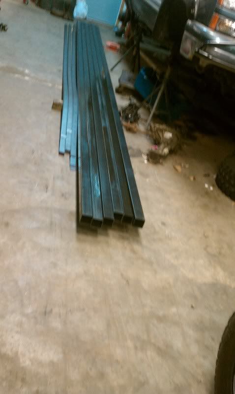
6 - 24' 3x3 x 10ga
25 - 20' 2 x 1/8" flat bar
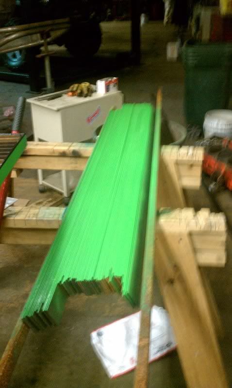
4 - 5' x 10' P&O 16 ga
1 - 6' x 12' 3/16"
For a total of $1,217...ouch. The price of steel is why I changed the design I posted earlier.
Well heres a few pics of the progress.
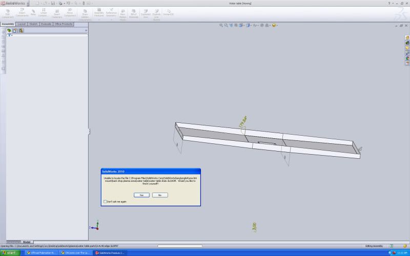
Simplified Solidworks drawing
Steel order
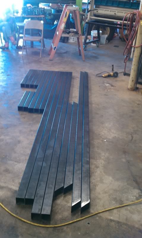
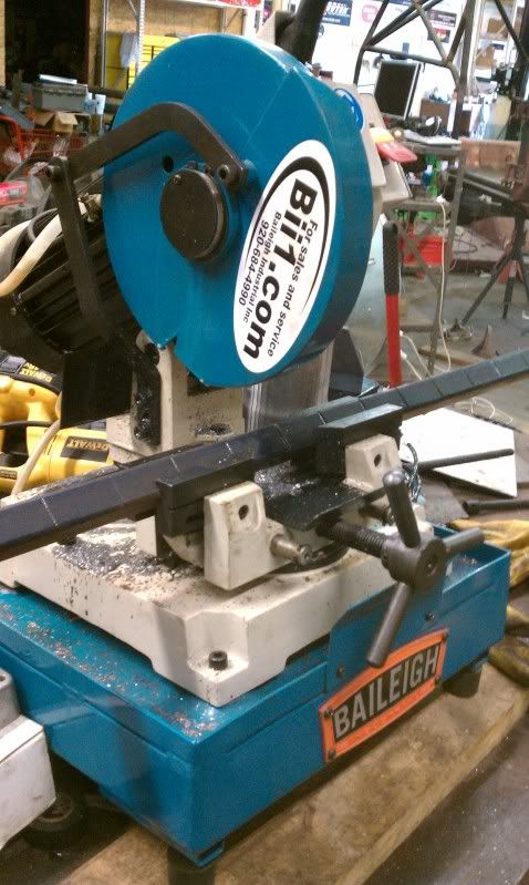
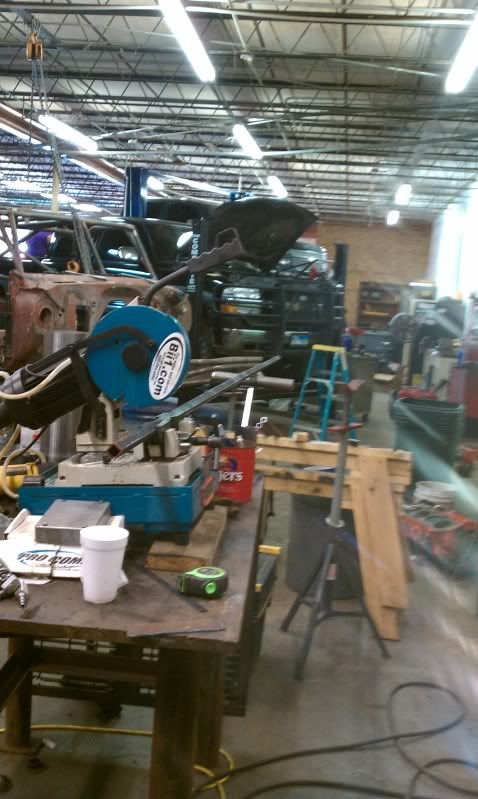
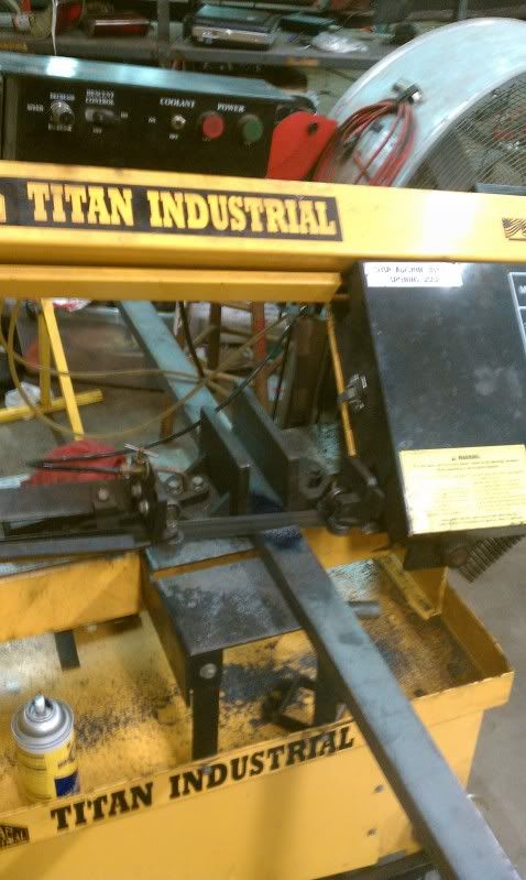
Setting up the band saw to start cutting everything down.
Everything cut out and ready to be assembled
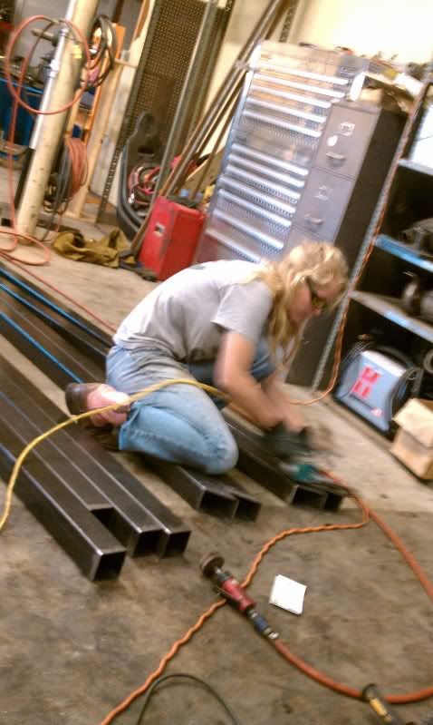
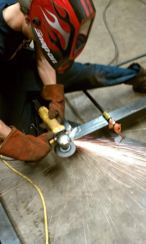
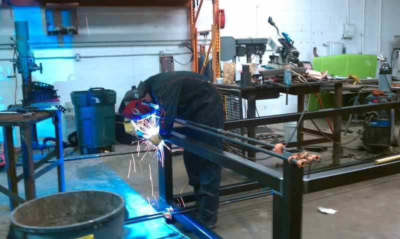
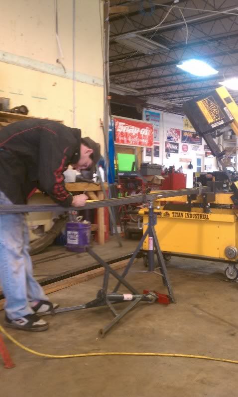
All the tubes being preped by my shop helper . Clean material for weld prep is critical for a sound weld and mill scale is the devil!
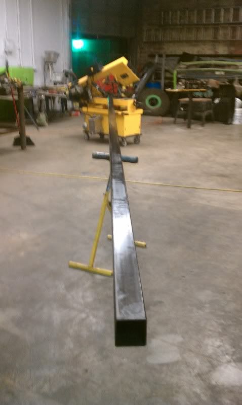
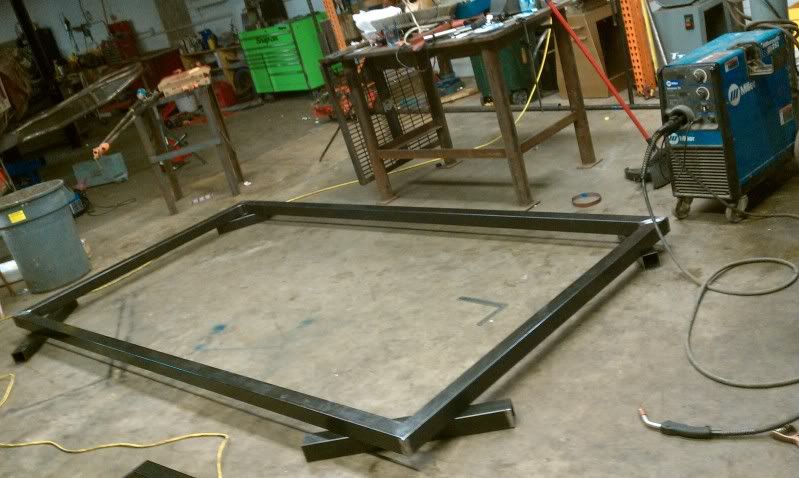
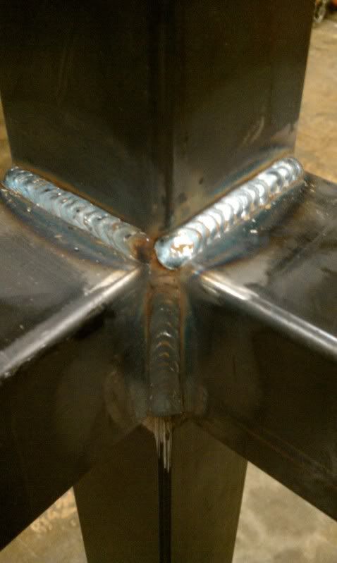
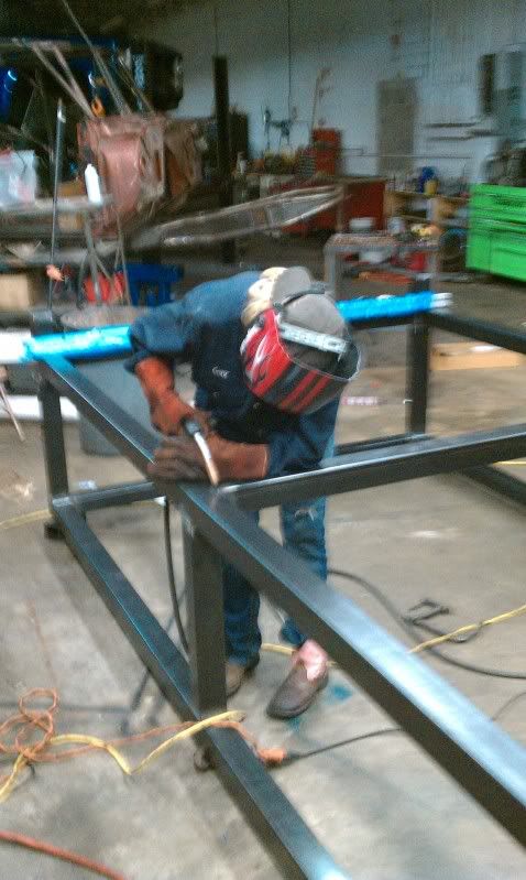
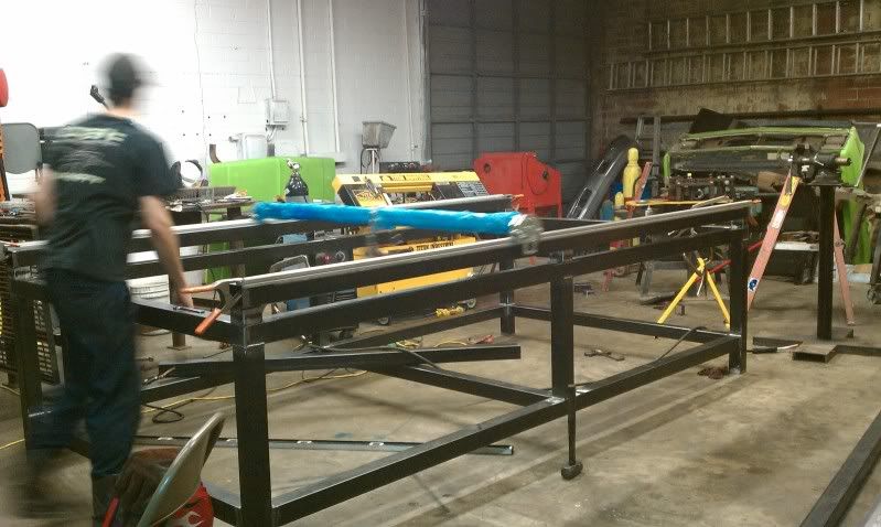
Heres the start of the frame going together. 45* at each corner for a cleaner look. Pipe clamps were used to keep everything in place as I laid the welds opposite of each other to minimize warping.
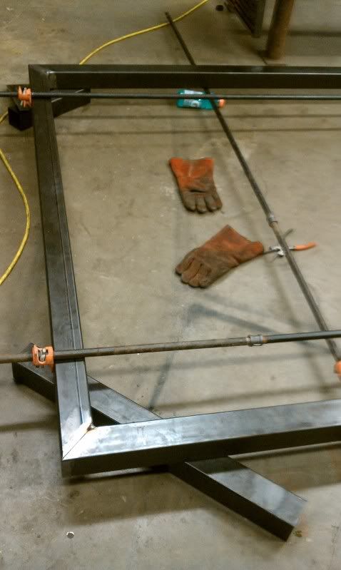
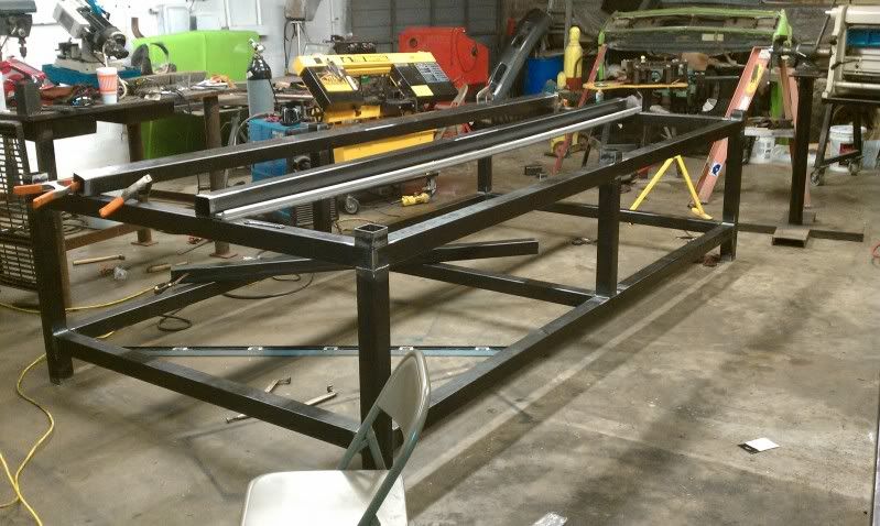
The base was then flipped to start attaching the legs.
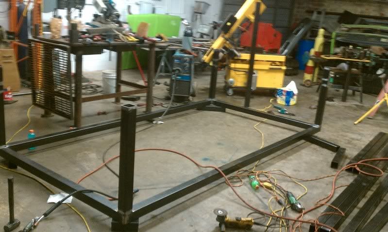
Then the rest of the structure was put into place.
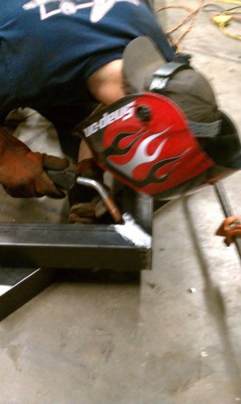
She had to put atleast one weld down on this or I would never hear the end of it.
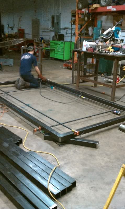
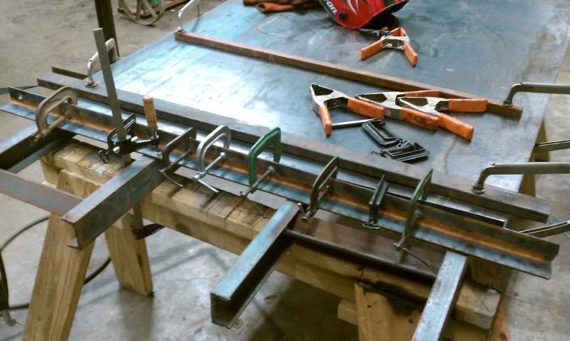
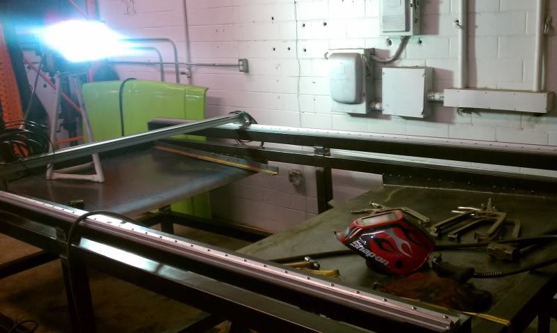
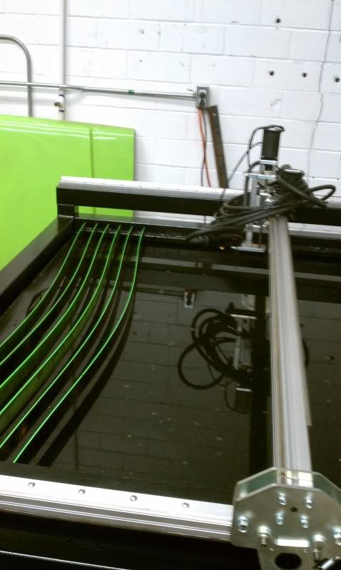
Once again the structure was flipped over and finished welded. Once finished the riser blocks were tacked in place and tubes that the linear rails will mount to were set and tacked in place. The rails were then clamped in place. The gantry was then assembled and put on the rails for a test run. A weight was added to help use the gantry a line up tool. As the gantry traveled down the rail it forced the rails square. This was a big help as the material I used had almost a 3/8" bend in it from one in to the other end.
I then measured opposite corners and verified the the rails were sq and parallel to each other. Once the position of the rails was set a transfer punch was used to mark 3 holes on each rail. Using the punch marks each hole was drilled out to a 7/ 32" and tapped to 1/4 - 20 to match the SS button head cap screws.
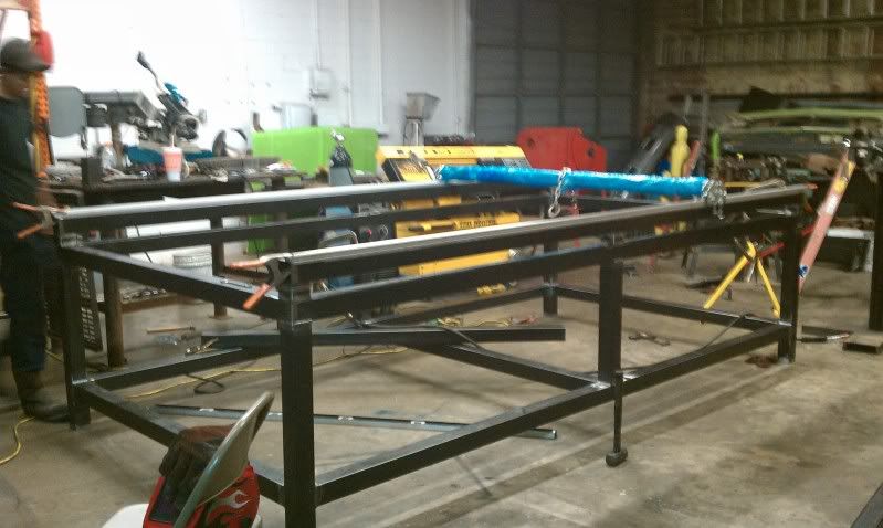
Well thats where I'm at now. I'll start again tomorrow. The goal is to complete everything by the end of the weekend. As always let me know what you think.
-
11-26-2010, 06:05 AM #6
Registered
- Join Date
- Feb 2005
- Posts
- 753
Looks good. Are you a welder by trade? Your welds look good.
-
11-26-2010, 09:25 AM #7
Registered
- Join Date
- Sep 2010
- Posts
- 0
Thanks, its been a long road to get this far. As far as welding I'm actually self taught, though I've considered making it full time. For now I just have part time performance and fabrication business in the corner of my dad's 4x4 shop. I'm hoping this table will help me tool up and start making enough to quit the day job of working on cranes.
-
11-26-2010, 03:42 PM #8
Registered
- Join Date
- Aug 2008
- Posts
- 21
Very good start to your table. An alternative to a holding tank for your water would be installing an air bladder. My table is pretty much the esame as yours, and I built an open tank that just fit inside the framework and seal welded it all around to the square tubing. I then built another inverted tank that is 1" smaller all around and the same distance off the bottom, and as deep as the slats will allow. In the corner by the controller, on top of the bladder I installed a 2" ball valve for the air discharge, and a 1/2" valve that is attached to shop air. With the 2" valve open, you can fill the tank with water to a level just below the top of the bladder (which will act as the bottom of your tank). This leaves very little surface area for evaporation to be a problem. When you open the air valve, the bladder will fill with air and displace the water inside. This will bring your water level up much faster than any pump. Opening the large valve will lower the water level each time you have to pick out small parts. It is a very efficient system that would work very well with your table.
Good luck, I am sure your customers will be impressed.
-
11-27-2010, 05:05 PM #9
Registered
- Join Date
- Sep 2010
- Posts
- 0
I'm trying to visualize your suggestion on the air bladder. So I need to build seal in the lower section of my table up to the rails. Then build a box inverted facing down with an air pocket under neath I would assume that by applying more or less air the middle box would rise and fall?
 If i'm understand this properly it wouldn't work in my situation. I need to be able to completely drain the table each night after use. The shop is less that a 1/4 mile from the Gulf of Mexico and the humidity is horrible. If I was to have a open water table sitting in the shop everything would turn to rust in a matter of days.
What I'm considering now is to find a 250 gal chemical storage tank that seems to b fairly common in my area and set it outside with a feed line running through the wall and up to the table. A simple submersible well pump should do the trick of moving the water back and forth in a timely manner.
Any one see a flaw in this plan? or a better way to construct a air bladder style water table? I really like the design plain ol bill used but, I didn't purchase enough material to complete a similar design.
-
11-27-2010, 06:41 PM #10
Registered
- Join Date
- Aug 2008
- Posts
- 21
The inner box which is inverted is fixed in position, and doesn't move. When you add water, it will fill close to the top. When you open the air valve, it pushes the water out and up the sides which are only an inch away from the walls of the main tank.Because of the large volume of water inside the inverted tank, and the small distance between the two walls, you can flood the tank very quickly. By releasing the air pressure and lowering the water below the top of the inverted box that your slats would be sitting on, you only have a 1" wide or less moat of water that would be exposed to evaporation. I have deflectors over this gap to prevent small pieces from falling down between the two, and this probably helps as well. We are in an extremely dry area, and as long as the water level is lowered when the table is not being used, we get very little evaporation. A lot more water is evaporated during the cutting of heavier plate than when the table is sitting idle. I hope this gives you a better idea of how the system works. The only mechanical components are the two valves, and of course a decent air compressor, which I assume you already have in place.
-
11-28-2010, 03:35 AM #11
Registered
- Join Date
- Sep 2010
- Posts
- 0
Ah that makes much more sense. Hmm.. I could see that being a very possible solution. I still have a question. Do you apply air to the inside of the inverted box thus pushing its water volume out and up the sides? If this is true then that would mean that the inverted box would need a vent for lack of a better word to allow the water to flow between the two areas. I would guess that by keeping the 2 boxed seal from each other with a valve in between is how it would be possible to control the water level?
And yes a large compressor isn't an issue. I have a 120gal speedaire with a refrigerated dryer inline.
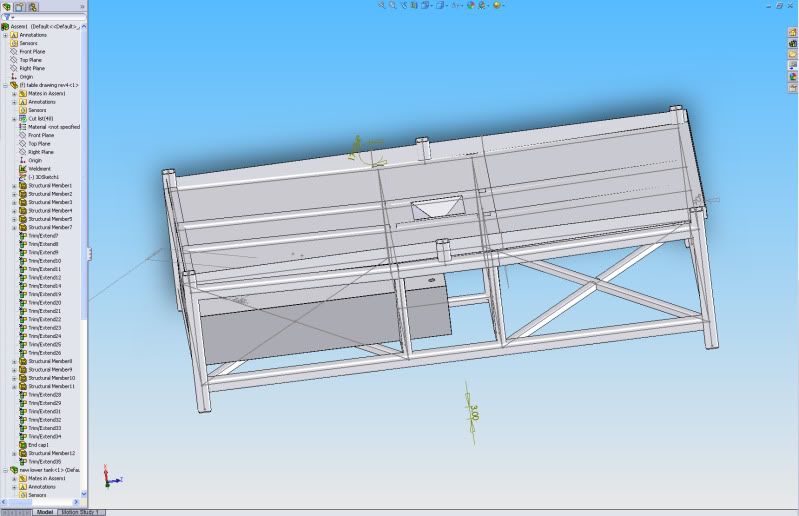
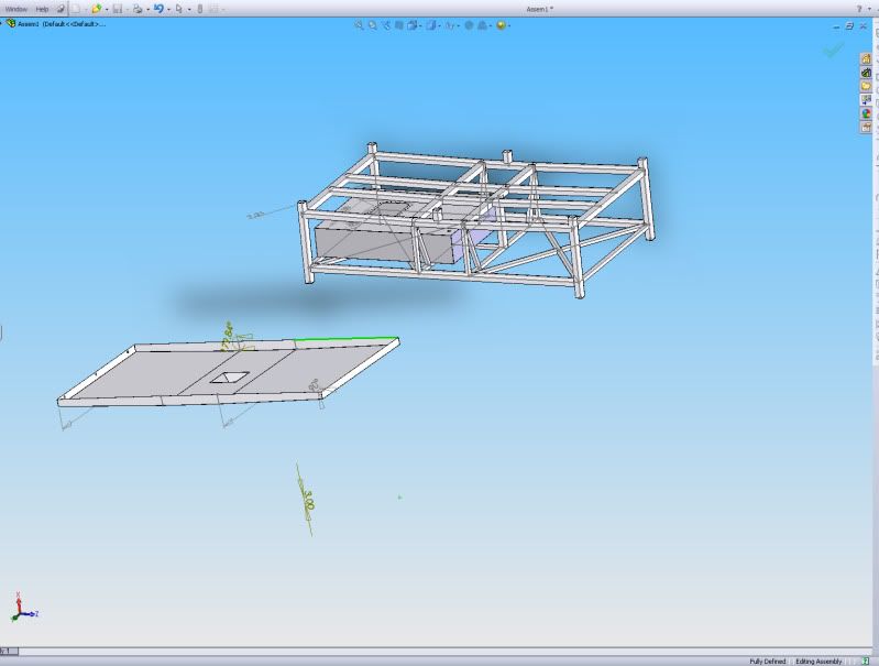
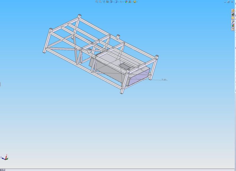
Heres a quick solidworks model I threw together. Am I on the right track?
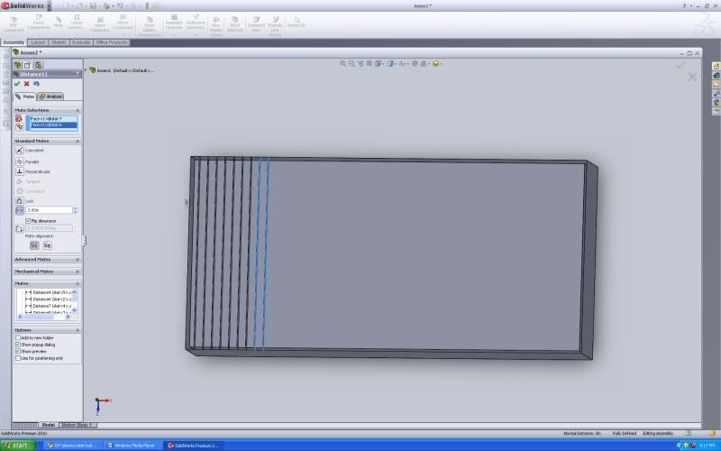
Thanks for the help.
-
11-28-2010, 03:48 PM #12
Registered
- Join Date
- Aug 2008
- Posts
- 21
I think you get my drift regarding the two tanks. The inner tank which is open on the bottom should be about 1" off of the floor of the main tank. The air inlet is on the most convenient corner (home position) on the top of the air bladder (inner tank). By opening the air valve the water is displaced very quickly. By closing the valve the water level will remain constant, assuming that you have no leaks. To lower the water level, simply open the 2" valve ( actually thelarger the better) to let the air escape, and the water will rush back in. When the large valve is left open, the water inside and outside will be at the same level. The larger the air supply line, the quicker it will build up pressure and force the water out and up. Also the less space between the two tanks, the quicker it will rise. The weight of the water will force the air out when you open the exhaust valve, but because there is a lot less pressure than you have with your air supply, a larger valve is required. When both valves are closed the water level will remain constant. If there isn't enough water in the tanks, air will be forced out when you are raising the water level, and will bubble violently around the edges. It probably gets more confusing the more I try to explain it, but it is really a simple and effective system.
-
11-28-2010, 08:06 PM #13
Registered
- Join Date
- Feb 2005
- Posts
- 753
Who makes those large clamps? I love them. Could come in really handy. Originally Posted by Txchevy

-
11-28-2010, 10:05 PM #14
Registered
- Join Date
- Sep 2010
- Posts
- 0
They are simple pipe clamps. One end screws on the end of a piece of 1/2" pipe while the other has a slip like most others. They work well for odd applications. To lengthen them just get another joint of 1/2" pipe and add a pipe coupler. They also make them in 3/4" sizes.
1/2"
Shop BESSEY 1/2" Pipe Clamp at Lowes.com
3/4"
Shop BESSEY 3/4" Pipe Clamp at Lowes.com
On a side note I have everything moving and started tuning the motors last night. I've stepped away from that to work on the water table and slat holders. I'll post more pics tonight.
-
12-08-2010, 09:55 PM #15
Registered
- Join Date
- Mar 2006
- Posts
- 489
Nice table build so far Tx.
I like the air bladder idea. Very simple concept, no pumps to wear out. Even if you used a chemical tank, I think you could apply the same principle by piping the outlet at the bottom of the tank to flood your water table using air only to displace the water in the chem tank. No?
-
12-14-2010, 07:59 AM #16
Registered
- Join Date
- Sep 2010
- Posts
- 0
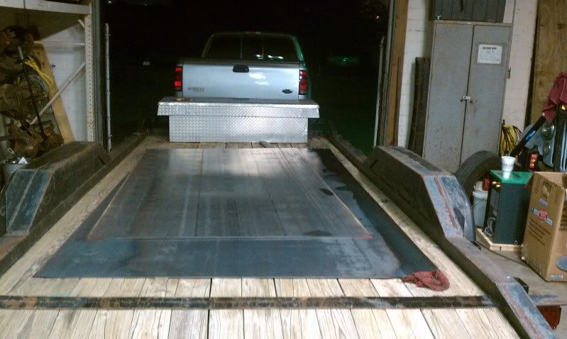
Well heres the update I promised. Things have slowed a bit due to work and life and general.
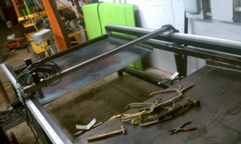
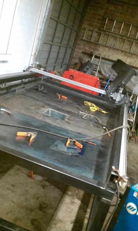
I really considered the air bladder concept but after, looking at the materials I had on hand and the overall design concept I started with I went with this design instead. I never seen another like it so maybe I'm way off in left field but we'll see soon enough.
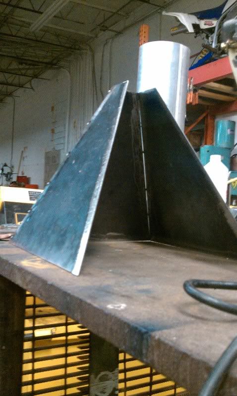
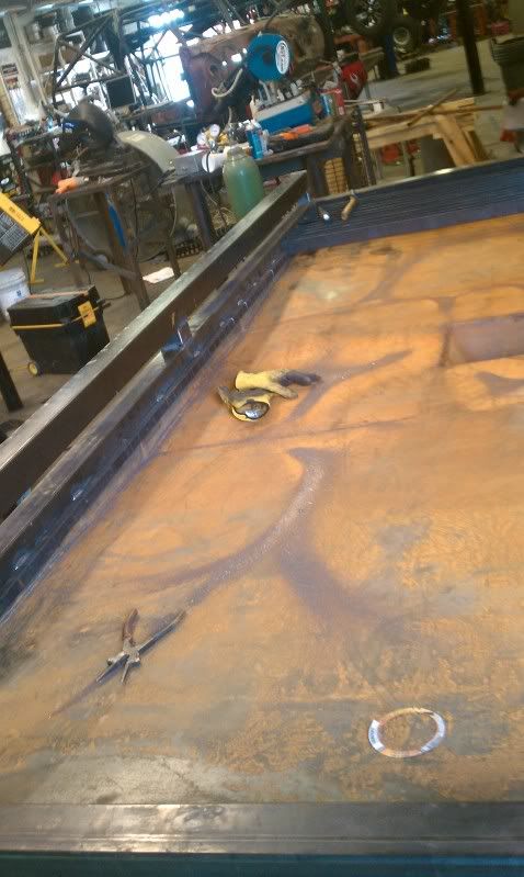
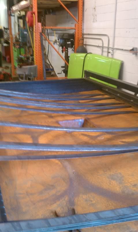
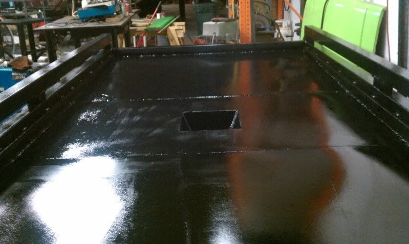
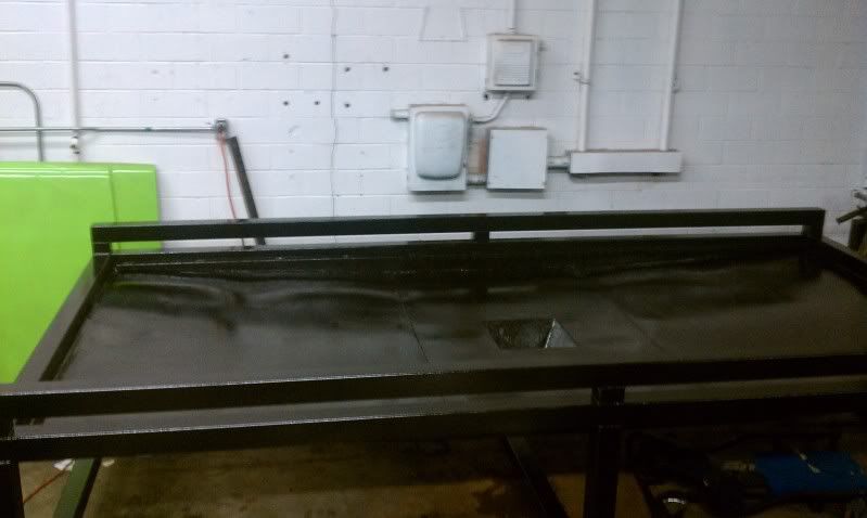
After looking at many different ways to design the water table portion I decided to build a sloped bottom table with a 12" x 12" drain in the center. The slope is 1/2" per 1 ft of drop so water drainage shouldn't be an issue. 16 ga was chosen due to the capacity of my baileigh shear. The water table design was also designed around tooling I currently have so that I could complete everything in house. I am slightly concerned with sagging of the table once water is added so a grid of 1x1 sq tubing may be added to the bottom when its tore down for blast and paint. with this design it will still allow me to build a water storage tank for down below as well store the control box and pc keeping everything self contained.
Anyways here some build pics
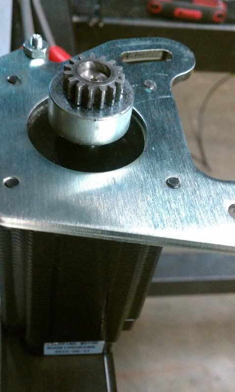
I had an issue with all the mounting holes on the stepper motors being too small for the supplied screws as well as too short. A quick stop at the drill press solved the hole size issue. The replacement allen bolts were a .125 longer and were causing issues. The longer boltss had to be clearanced due to the way the tension was designed the motor mount plate and the carriage plate are face to face. With the new longer bolts I had a problem with the pinion gear not meshing properly with the rack due to them not being parallel to each other. After a few passes on the new longer bolts the extra threads were ground down and the hand finished with a machinist file. No more misaligned pinion gear!
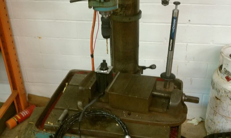
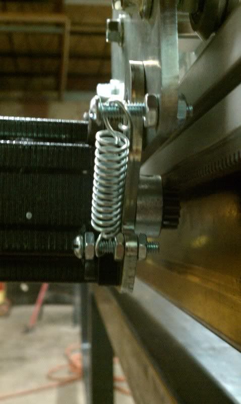
Disregard the tension spring setup above it was removed due to the tension not being applied inline with the plate and actually pulling the pinion out of alignment.

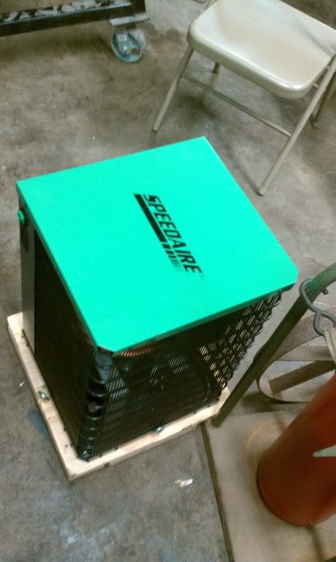
pic of the new dryer I picked up last week
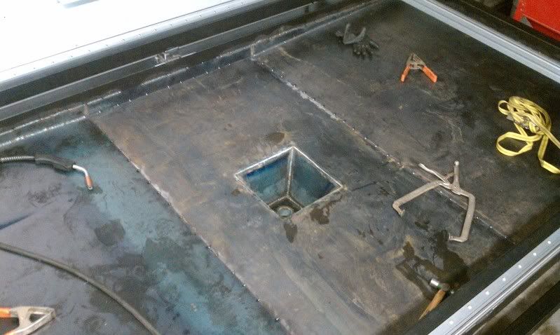
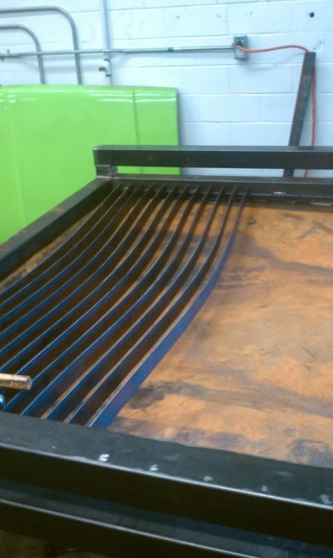
both end slopes are welded in place next up the center plate
the depth of the drain will most likely be modified as well as a drain cover made after the table is operational.
Let me know what ya'll think.
Thanks
-
12-14-2010, 03:58 PM #17
Registered
- Join Date
- Mar 2006
- Posts
- 489
I think it looks great, although your helper looks a little bored, or maybe contemplative is a better word.

Did you make the spring loaded motor/pinion plate? I've been designing a spring loaded mechanism for my new table too. Any idea how much spring force is required? I think I read somewhere that 40lbs is sufficient. I can easily get that in a gas shock, but a tension spring doesn't look as easy to fit into my design.
What are your thoughts behind the hopper for the drain? Not sure if I follow you on that one.
Paul
-
12-17-2010, 07:44 AM #18
Registered
- Join Date
- Sep 2010
- Posts
- 0
Ya she tends to crash on the creeper alot when i'm in the shop lol.
I used the gantry kit from Ron at Prescion plasma. So far everything has come together very well. The springs were provided with the kit so my guess on tension is probably around 35-40 ft lbs to get them to move. Post up a pic when you build your tension plates. I'm interested to see what you come up with, as I would like to build new plates in the future to add some wheel base and stability to the gantry if needed.
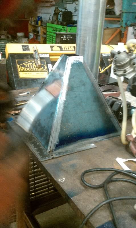
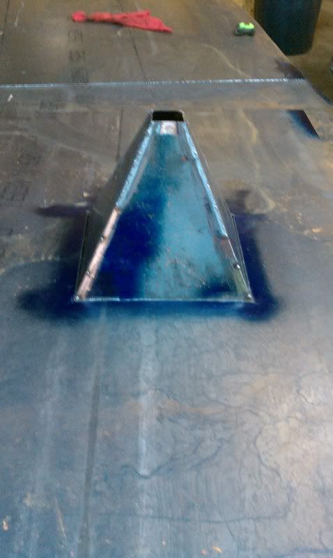
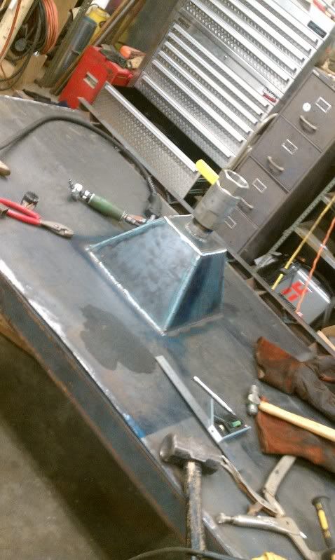
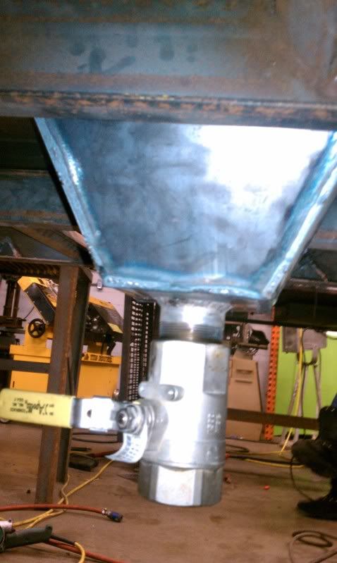
The plan with the hopper style drain is to allow water to fall into a 12" x 12" opening and then a 2" drain similar to a funnel effect, instead of a flat surface draining into a 2" hole in the plate. I think with the slope built into the water bed and the large drain. I should be able to very quickly drain the table for cutting aluminum or shutting down for the day as I will drain the table each day. I plan to cut out a trick drain cover to prevent drops from clogging the drain or tearing up the SS ball valve.
Well here is tonight's progress:
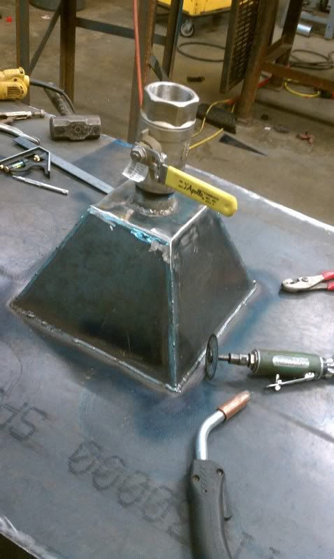
Made the drain plate from 16 ga sheet and a 2" galvanized pipe nipple cut to fit. The hopper side as ground and smoothed for a seamless transition. FYI be very careful when welding galvanized material as the fumes can make you very sick if precautions are not taken to prevent inhalation.

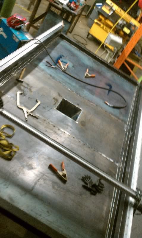
I found a 2" Stainless Steel ball valve I had laying around from work that worked perfectly.
Water test... One tiny pinhole was found, not bad for my 1st time welding thin sheet metal out of position.
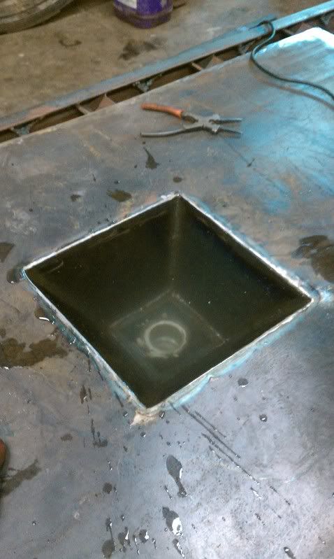
Center drain plate in its final place being tacked in. Everything will be finish
welded after work tomorrow. I ran out of time this evening. Then another water test. If all goes well and no leaks are left I should have the slats in place by Friday evening.
As always let me know what you think.
-
01-09-2011, 10:09 PM #19
Registered
- Join Date
- Sep 2010
- Posts
- 0
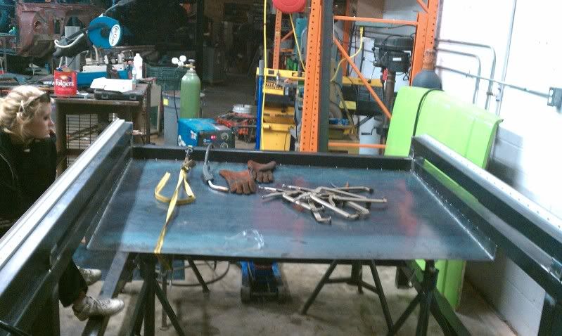
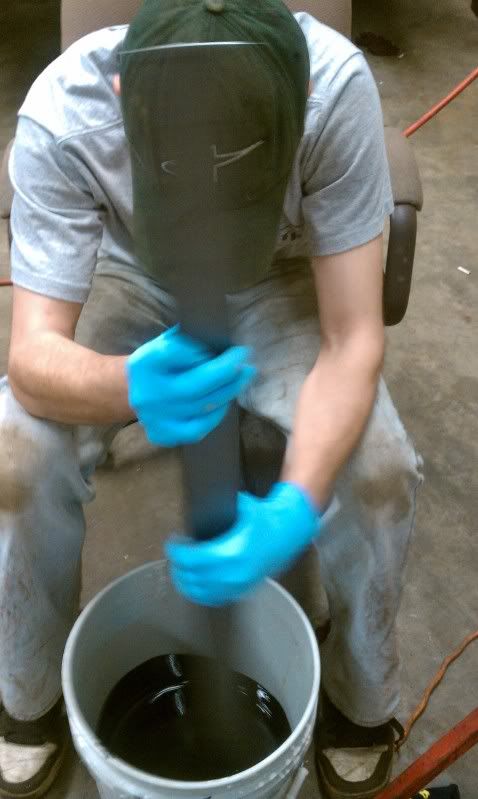
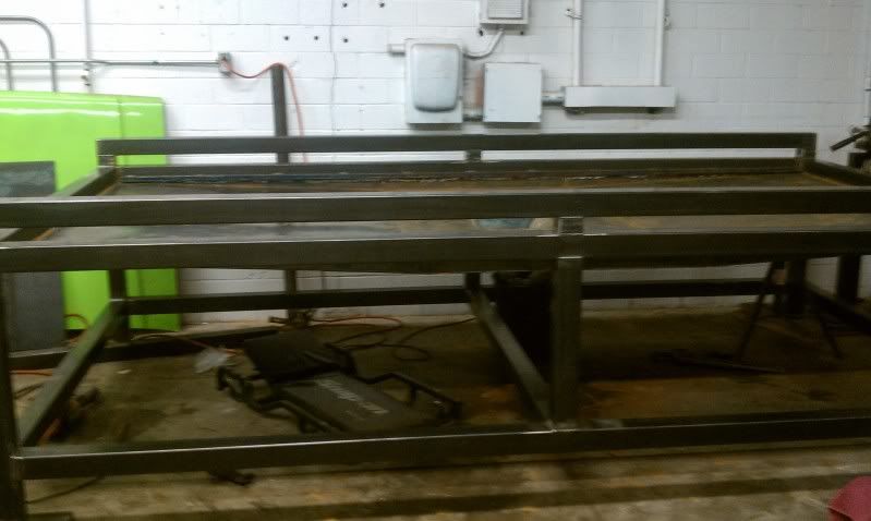
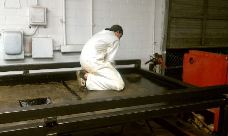
Well Its been a long last month but, it seems the majority of the fabrication is complete for the moment. I completed the water table and slat holder last week then everything was water tested with No leaks! Once that was completed I pulled everything off and gave it two coats of a gloss black 2 part industrial epoxy paint. So far everything has been going great.
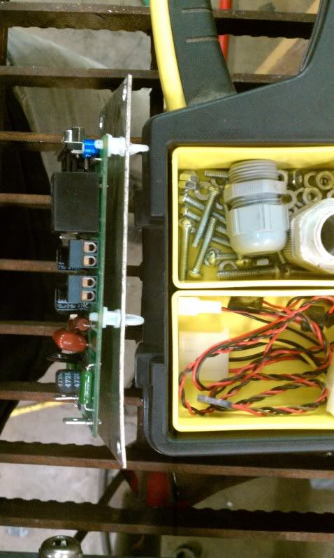
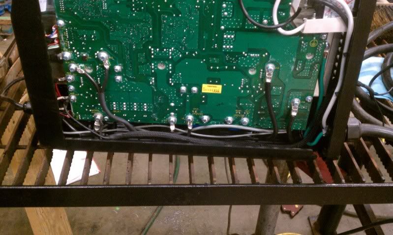
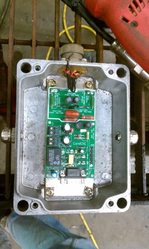
Next, I tapped into the plasma and and made my connections for the dthc card. I used 16 gauge wire and installed a weatherpack connector on the arc OK wires leaving the powermax 45. This allows me to disconnect the unti and use it elsewhere in the shop if the need should arise. For the dthc card I made a custom interface cable and used a left over nema enclosure from work for the card mount.
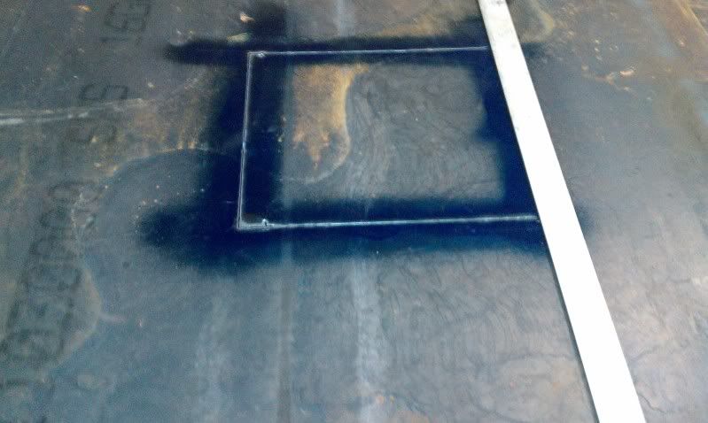
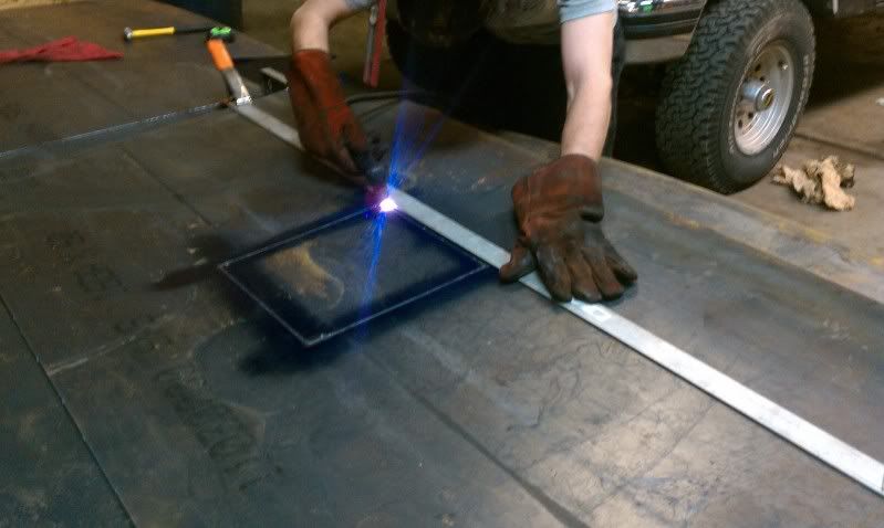
I started tunning the motors and after some trouble have that pretty much set. I'm now fighting the dthc and firing of the torch. I continusly get a fault starting tip volts out of range and everything stops moving. I decided maybe the roadrunner that came with mach3 wasn't the best thing to start cutting so I made a simple 3x2" plate with 3 1" holes then ran sheetcam to produce the g-code everything seemed fine during this process. I did notice there wasn't a selection for a post processor for the mp3000 only the mp1000 so that is the one i selected. When the G code was loaded into mach is says an error that has something to do with j??? I decided to ignore it. I hit run and the z goes nuts and travels straight down crashing into the plate and them limiting it self out.
I'm at a loss as to what should be my next step. I believe its something simple, a parameter thats not set properly, or maybe a dthc issue but, I can't determine what or where. It feels like I'm trying to make something work without all the info. I have several interested customers but, I can't follow up with them if i can't make the table work. HELP PLZ!!!!!
And as usual heres the pics
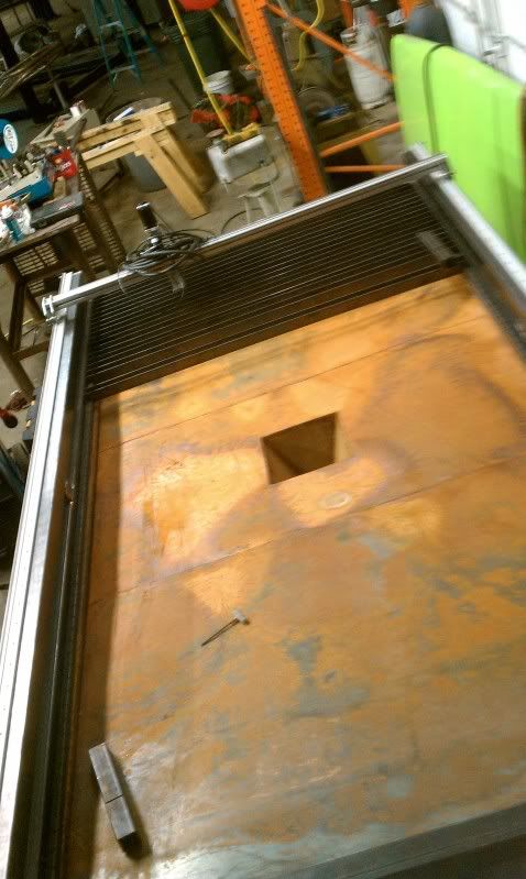

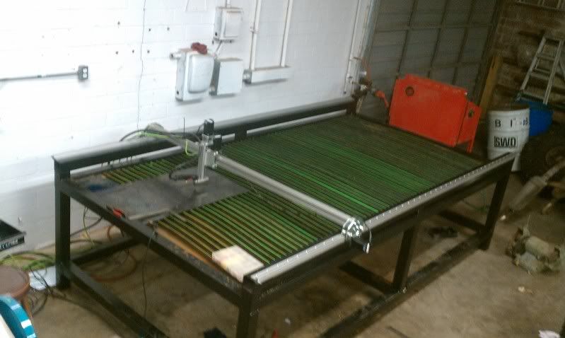
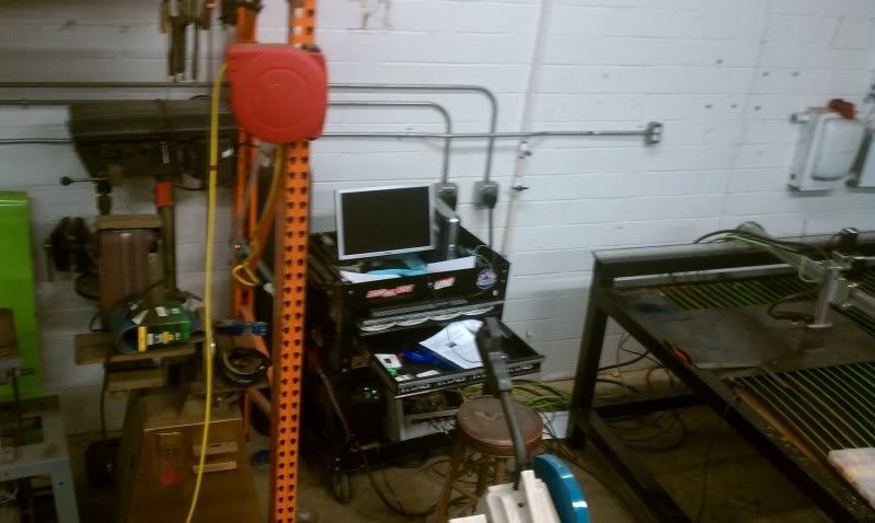
And here its sits today
-
07-31-2011, 11:51 AM #20
Registered
- Join Date
- Jul 2011
- Posts
- 0
Cool table. Update?

 Reply With Quote
Similar Threads
-
Newbie - To build or not to build Router/Plasma Table
By dfranks in forum Waterjet General TopicsReplies: 10Last Post: 04-08-2011, 05:16 AM -
Joe's 4x4 hybrid build/2006 build
By krap101 in forum DIY CNC Router Table MachinesReplies: 1Last Post: 08-09-2010, 11:30 AM -
NEW BUILD: PVC as a build material
By Smiler in forum DIY CNC Router Table MachinesReplies: 12Last Post: 11-13-2009, 11:57 PM -
New Large Table Build in Houston, TX (Build Log)
By anitel in forum Plasma, EDM / Other similar machine Project LogReplies: 12Last Post: 12-30-2008, 09:45 AM
