


About me:
I'm a senior studying Mechanical Engineering at OIT in Oregon. So I've taken some CAD/CAM classes and enjoying it thoroughly. I'm fortunate that my school teaches us welding and machining in full fledged classes with proper equipment. In 2009 I started on the project to build a budget CNC machine with a friend.
Project Background
So I started off on a 1000$ budget and very little equipment access, with the intent to cut costs as much as possible to simply get our first machine made. The machine was originally intended to cut both metal, and wood. The idea was to have a huge work range, but the importance of frame stiffness had eluded me at that time (young, nieve, etc..)
Summer ended, after some substantial research, design, and purchasing (but not a enough.) The project has been on the backburner ever since, as school came first. I got a high paying internship (20K over 6 months) and now have the financial backing to "do it right."
I'm caught in a quandry of design directions. I can either backyard engineer up the final 40%, or take a step back. Go back to the drawing board, shore up the details, and have a decent machine (or so I think.)
Current Hardware:
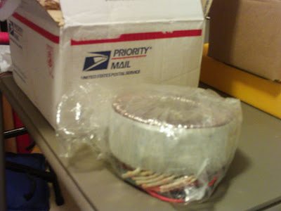
- Antek Transformer - Toroid Transformer (currently wired @ 24VDC) wasn't aware of Vrms at the time... I think i can rewire it for 48VDC, but my control board can't take more than 36VDC. Used this to make a powersupply with help from my EE friend.
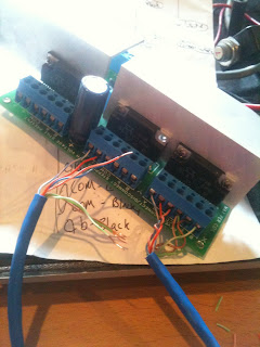
- Control Board - HobbyCNC 36VDC board/drivers only. Soldered this badboy up. Added .125" aluminum angle iron as heatsink for drivers.
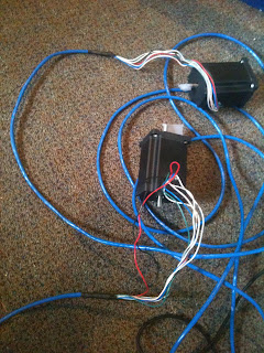
- 3 Keling 425 oz-in Steppers - Wired these in unipolar mode running at 2 amps. I'm concerned about power over lines because we used the unshielded RJ-45 cable i had (8x24AWG wire).
- Homebuilt computer - This was my lanning computer from high school, I have mach installed on it. It can supply a reasonably clean 25Khz pulse stream.
- Ballscrews - Purchased set of 3 via linearmotionbearings from ebay. Custom sized to match the linear bearings geometry. Slightly oversized compared to linear bearings to make life easy. C7 Tolerance. Got tired of trying to buy ground ballscrews off ebay. Got the complete set for 375 shipped. Came with everything I needed for the ballscrews. Not bad.
- Profile Rails - Purchased via lots of patience on ebay. THK rails. From memory, they are SRS blocks for the X and Y axis. SHS for the Z-axis.
- Work Range With the components above and saddle plates of ranging 8-10" in height the effective work range is about:
- X-axis = 22.28 in
- Y-axis = 19.88 in
- Z-axis = 12.38 in
Designs
The old/original design.
The Wood Frame components- as it is right now. If you are wondering why i did this... 1) I don't fear messing up. 2) I had 1 free week to work on this with only a skill saw, and harbor freight hand power drill. 3) I knew I'd learn something for about less than 20$ of 2x4's. 4) Completely reversible.
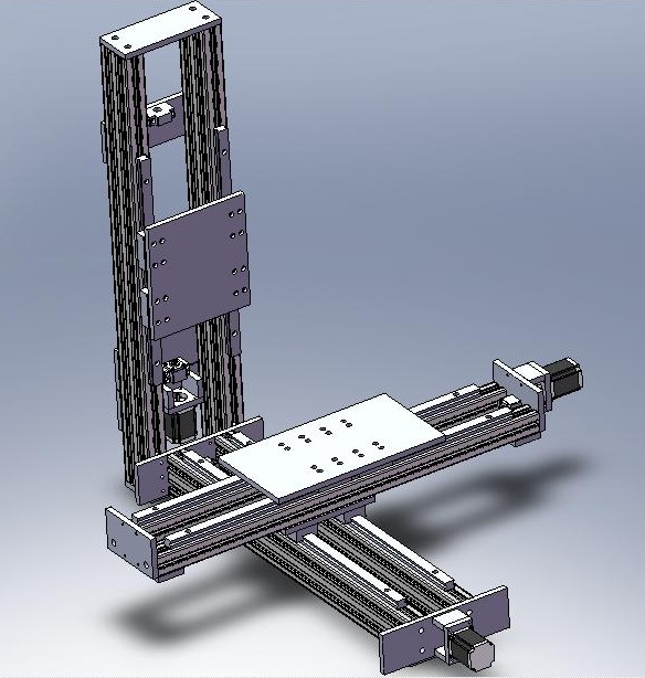
Due to the realization, I can't go any further without a solid plan, I started modeling everything I could. Here is just one axis I am working on modeling. (Work in progress)
Future considerations
Given that I have a transformer running at half of it what it is capable (48VDC,) I want to upgrade the control board to some sort of Gecko board. I recall they can take up to 80VDC. Perhaps with easy connect/disconnects. Money is no longer as much an issue for the build. This seems like a reasonable upgrade, and i'll have an extra control board to build a smaller machine.
I feel the calling to change to some shielded wire, and with higher gage. I'm not sure what is optimal yet, haven't dug into the equation for resistance based on diameter. Any vendor or product suggestions?
I also need to find a better lubricant - preferably one that is dry. I've heard rumors of mysterious substances that don't are dry, work well, and are clean. Everything sat for so long it started to rust a tiny bit. I've been using some spray on white lithium grease so far in an attempt to protect all the linear motion systems. Unfortunately, it collects a lot of dust (better than rust :P).
Major Design Decision
After successfully modeling all the components I have currently, I will explore the various machine configurations. The big decision is how to proceed with the frame design/build from here. I have near complete wood frames built with 2x4's, but I have the resources(bridgeport mills) to finish this machine off right with aluminum extruded frame. Hopefully I get around to calculating the moment arm, and deflection based on extrusion section modulus while considering frame configurations.
Here are some sketches of the configurations I'd like to consider. Please forgive my HORRIBLE handwriting. I didn't intend sharing this document when i drew it up.

I think I'll try to quickly finish the machine with the wood frame, and then move to convert the machine to a sturdy 80-20 frame. Yet, due to my huge work range, I question the machine's ability to even be rigid enough to cut anything reliably with a wood frame.
Either way i'm going to completely model everything, before I build it from here on out (lesson learned.)
I welcome any advice, suggestions, recommendations, or questions with open arms and ears!
Thread: nickswimsfast's CNC Build Log
Results 1 to 20 of 74
Threaded View
-
03-28-2011, 11:49 AM #1
 Registered
- Join Date
- Jul 2009
- Posts
- 60
nickswimsfast's CNC Build Log
Would the stars shine if nobody were there to observe them?


 Reply With Quote
Similar Threads
-
Build Log: RMGVideos XZero Raptor Build
By sagreen in forum DIY CNC Router Table MachinesReplies: 150Last Post: 05-10-2011, 09:00 PM -
Newbie - To build or not to build Router/Plasma Table
By dfranks in forum Waterjet General TopicsReplies: 10Last Post: 04-08-2011, 05:16 AM -
Joe's 4x4 hybrid build/2006 build
By krap101 in forum DIY CNC Router Table MachinesReplies: 1Last Post: 08-09-2010, 11:30 AM -
New Large Table Build in Houston, TX (Build Log)
By anitel in forum Plasma, EDM / Other similar machine Project LogReplies: 12Last Post: 12-30-2008, 09:45 AM
