


I'm having some trouble getting my Keling 5056D drivers and C10 BOB to turn my Keling 570oz-in motors with Mach3.
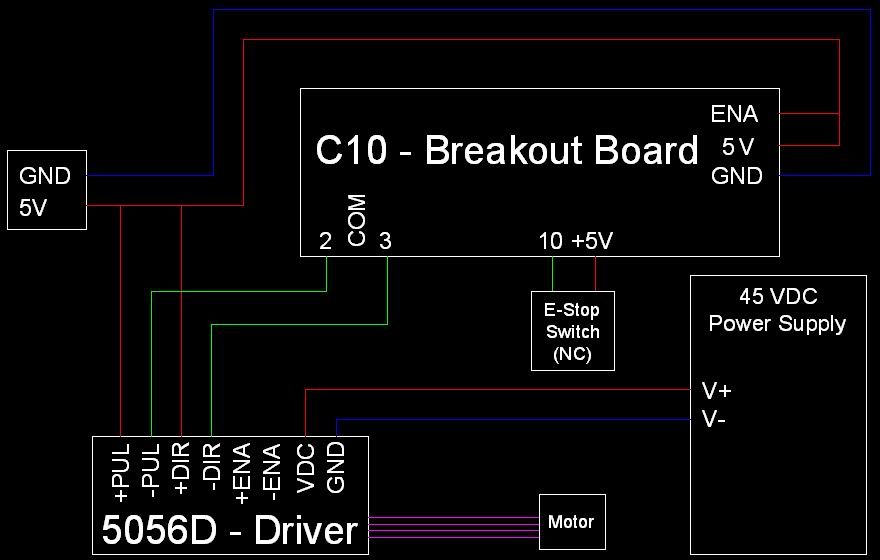
I have them hooked up like the picture below, but left out the other 2 motors for clarity.
Mach3 Motor Outputs settings are as follows:
X-Axis Step Pin# = 2
X-Axis Dir Pin# = 3
X-Axis Step Port = 1
X-Axis Dir Port = 1
Neither have Dir LowActive or Step Low Active checked.
I've also got the Estop set to pin 10, and it works as expected.
In Motor Tuning, I have X-axis set up as follows:
Steps Per: 4000
Velocity: 100
Acceleration: 50
G's = .1295...
Step Pulse 1-5us: 3
Dir Pulse 1-5us: 3
I have the Step and Dir Pulse set to 3 because the 1-2us Mach3 uses wasn't quite up to the 2.5us the 5056D datasheets said to use.
I've got the DIP switches set as:
1-on
2-on
3-on
4-off
5-on
6-on
7-on
8-on
which, I believe, means 5.6A Peak Current, half standstill current and no microstepping.
When I turn on the 45VDC power supply, the motor locks up, and I get a green LED on the 5056D, but no motor motion.
I feel like it's something very simple, like Mach3 is in simulation mode, but if that were the case, would the Estop switch still work?
Any help would be greatly appreciated!
Results 1 to 20 of 38
-
04-19-2011, 03:32 AM #1
 Registered
- Join Date
- Jan 2005
- Posts
- 136
Keling 5056D, Keling C10 BOB and Mach3 problem.
-
04-19-2011, 04:18 AM #2
Member

- Join Date
- Oct 2005
- Posts
- 906
 Originally Posted by tobybirch007

Check here for mach3 setup
http://www.kelinginc.net/Mach3setup.pdf
check the sherline 1/2 pluse mode
Best Stepper Motor, Stepper Motor Driver,CNC Router, Stepper Motor Power Supply, Stepper Motor Kit,DC Servo Motor
-
04-19-2011, 04:29 AM #3
Registered
- Join Date
- Jan 2005
- Posts
- 136
This is little misleading. The picture of the port setup page show's sherline 1/2 puls mode selected, but the following text says to "make sure that none of the options on the right side is enabled"
So, which is it? EDIT4: It says directly above the picture to "Remember to click Sherline ½ Pulse mode"
EDIT: Also, what are the jumper settings?
EDIT2: Are there any standard colors for the wires on the motor? EDIT3: Yes, on the diagram for the 5056 & C10 here
-
04-19-2011, 06:54 AM #4
Registered
- Join Date
- Apr 2009
- Posts
- 7
Hi...
According to my drawing...the E Stop switch should be hooked between 10 and Ground
not to the +5 . Do you have the 5056 drawing from Kellinc? If Not give me an E-MaIL and I will send it to you. Mine Is [email protected].
-
04-19-2011, 01:40 PM #5
Registered
- Join Date
- Jan 2005
- Posts
- 136
I think you can do it both ways, but the way I have it works and is shown on
http://www.kelinginc.net/KL-5056WithC10.pdf
as connected through 5V. I think I had to set it as Active Low in order to work, which causes an external Estop if the BOB fails. I'll check the settings at lunch or after work.
-
04-19-2011, 04:42 PM #6
Community Moderator
- Join Date
- Mar 2003
- Posts
- 35538
Make sure the port address is correct.
Gerry
UCCNC 2017 Screenset
http://www.thecncwoodworker.com/2017.html
Mach3 2010 Screenset
http://www.thecncwoodworker.com/2010.html
JointCAM - CNC Dovetails & Box Joints
http://www.g-forcecnc.com/jointcam.html
(Note: The opinions expressed in this post are my own and are not necessarily those of CNCzone and its management)
-
04-20-2011, 05:27 AM #7
Registered
- Join Date
- Jan 2005
- Posts
- 136
1.) Am I correct in my thinking, that the BOB put's out 5v on the numbered output pins when the signal is sent from the parallel port?
2.) This 5v should go into either the PUL+ or DIR+ of the 5056D drivers?
3.) The PUL- and DIR- should be connected to GND, either of the 5V power supply or a COM pin on the BOB with the 5v/GND jumper set to GND?
4.) Nothing attached to the ENA+ or ENA-?
5.) Should the -V from the KL-600-48 power supply be tied to the GND from the 5v power supply?
6.) Can someone tell me what the 5056 DIP switches should be set at for these motors?
I'm going crazy guys! I've tried every diagram out there, followed the mach settings, and all I get is the motor holding in place!!
-
04-20-2011, 03:19 PM #8
Gold Member
- Join Date
- Jan 2010
- Posts
- 2141
I do not have either the C10 or the 5056, so I can't give any guidance from direct experience, so my comments are based on my reading of the available documentation...
Do you have (access to) an oscilloscope? That will help you to narrow down whether you should be focusing on Mach or on the breakout board or the driver.
Is the C10 jumper X6 set for output?
>>1.) Am I correct in my thinking, that the BOB put's out 5v on the numbered output pins when the signal is sent from the parallel port?
My interpretation of the C10 manual is that with your Mach3 settings (step low active set to Red), the step pulse input from the PC should be normally low with a positive-going pulse (for each step), and likewise the step pulse output from the C10 on pin 2 should be low with a positive-going pulse (in other words, it does not look like the C10 performs an inversion on that signal). It would be best if you could use an oscilloscope to verify that on pin 2.
As for the direction signal (Dir low active set to red, but it wouldn't make a big difference if it were set to green because motor direction can always be changed easily by motor wiring), my interpretation is that you should be able to test pin 3 with a multimeter, because the direction pin should be a steady 5 volt "high" signal if you are jogging an axis in one direction, and a steady 0 volt "low" signal if you are jogging in the opposite direction.
>>2.) This 5v should go into either the PUL+ or DIR+ of the 5056D drivers?
>>3.) The PUL- and DIR- should be connected to GND, either of the 5V power supply or a COM pin on the BOB with the 5v/GND jumper set to GND?
My interpretation is that pin 2 from the C10 should go to PUL- of the 5056D, and pin 3 from the C10 should go to DIR- of the 5056D, just as you have shown in your diagram.
Also, steady 5 volts should go to PUL+ and DIR+ of the 5056D, just as you have shown in your diagram.
>>4.) Nothing attached to the ENA+ or ENA-?
According to the manual, Usually left UNCONNECTED (ENABLED)
>>5.) Should the -V from the KL-600-48 power supply be tied to the GND from the 5v power supply?
It appears to me that the 5056D uses optoisolated inputs, with the 5 volt connection to the PUL+ and DIR+ pins going to the input side of the optoisolators, and therefore to maintain that isolation, I would NOT tie the -V from the KL-600-48 to the GND of the 5v power supply.
>>6.) Can someone tell me what the 5056 DIP switches should be set at for these motors?
Pins 1, 2, 3, and 4 look OK to me.
I would try starting out with pin 5 set to OFF, and 6, 7, 8 set to ON (for initial testing with half stepping).
The configuration that you showed (with 5, 6, 7, and 8 set to ON) appears to be valid only for "software configuration", however it does not appear to me that you are using that.
I would also note that the KL-600-48 is rated for 48 volts output, while the KL-5056D ordering page states that it is only rated for Supply voltage up to +45 VDC. It may be that that rating is conservative and you will be OK, but it's something to be aware of.
-
04-20-2011, 11:14 PM #9
Registered
- Join Date
- Jan 2005
- Posts
- 136
I brought an Oscope home from work today, so I'll know what's going on soon enough!
I thought the same thing about step and dir low active, but at http://www.kelinginc.net/Mach3setup.pdf it says to have them set as low active, unless the picture is incorrect.
-
04-20-2011, 11:18 PM #10
Gold Member
- Join Date
- Jan 2010
- Posts
- 2141
It shouldn't matter for the Direction pin, because the direction that the motor rotates (CW or CCW) depends on the motor wiring as well. Originally Posted by tobybirch007
It probably does not matter for the Step signal, because whether the step is actuated by a positive-going transition or a negative-going transition, a single step pulse will have both a positive-going and a negative-going transition, regardless of whether the pin is defined as active high or active low.
You might want to check with the oscilloscope to see whether one of the pulse edges is sharper than the other, though, because it's probably better to have a sharp transition on that pulse than to have a soft transition.
-
04-21-2011, 12:41 AM #11
Registered
- Join Date
- Jan 2005
- Posts
- 136
Well, I got them working finally, but I think there's something wrong with my BOB, as the pin's on the silkscreen didn't correspond with the pins in mach. They are as follows:
Mach3 says / Output's on BOB
2/9
3/8
4/7
5/6
6/5
7/4
it looks to me that either:
a.) There is something wrong with my PC, Mach3, Mach3 parallel drivers, PC parallel port or parallel cable.
b.) One of the chips on my BOB is bad or flipped or something.
Anyway, now that that's over...
Doorknob, I think it does matter because these drives are opto-isolated and current will only activate the opto-isolator if it is going the right way.
With Mach3 setup as LowActive, you would want the common pins set to GND, run the control wire to the -PUL and run 5v to the +PUL. At least I think this is how you would do it. I didn't.
I have mine setup like this
Mach 3 is NOT LowActive, COM pin's are set to GND, and the control pins are pulled DOWN.
The control wires are connected to +pul, the -pul are connected to the COM (GND) pins. This means that when the signal comes in from Mach3 it is a low to high pulse, causing current to flow across the opto-isolator to GND and turning the motor.
Does this seem like a bad way of doing it to anyone?
Also, does anyone know why we're supposed to use the Sherline 1/2 pulse mode? I turned mine off and it seems to work fine.
WHEW!!
-
04-21-2011, 01:14 AM #12
Gold Member
- Join Date
- Jan 2010
- Posts
- 2141
Glad to hear that you got it working. :banana:
The documentation for the 5056D is remarkably poor. According to figure 10 of the manual, it looks like step might activate on a negative-going pulse edge. But does not specify that the negative-going edge must be the leading edge of the pulse. Each step pulse has both a positive-going edge and a negative-going edge.
The optoisolator can be hooked up in more than one way. The diagram in figure 9 shows the LED turning on when a steady positive voltage is applied to PUL+ and PUL- goes negative (in other words, if both PUL+ and PUL- are high, the internal LED is off, but pulling PUL- to ground turns it on). However it can also work the way that you have wired it, where the pulse going positive on PUL+ (and PUL- grounded) turns on the optoisolator.
It was useful for me to go through the exercise, though...
-
04-21-2011, 02:26 AM #13
Registered
- Join Date
- Jan 2005
- Posts
- 136
That's what I was getting at. What is the benefit of doing it the other way? Originally Posted by doorknob
-
04-21-2011, 02:42 AM #14
Gold Member
- Join Date
- Jan 2010
- Posts
- 2141
Without more detailed information I can only guess.
One thing that comes to mind is that some circuits are able to sink a large amount of current, but can only source a little bit of current, while others may be designed to do the opposite.
An optoisolator input probably draws a fair amount of current, perhaps a few mA. or more (because it needs to turn on an LED). If you're driving that input with, for example, a TTL gate or any kind of open collector that is designed to sink current, it will do best with the hookup that puts a steady +5v on PUL+ with the signal on PUL- (so that when the signal goes low, it sinks current to turn on the opto).
Judging by the C10 documentation, the output looks like it comes from a high-current buffer that can probably handle either sourcing or sinking sufficient current to drive an optoisolator input. So that probably explains why it will work either way for you.
-
04-21-2011, 06:52 AM #15
Registered
- Join Date
- Apr 2009
- Posts
- 7
Breakout Box
Hi...
I have seen the replies and conclude after loking at the C10 setup that you really need to be using the DB25. You need to go back to the site and look.
A group of series switches all hooed in series to one point will not work.
That drawing is not correct on the Kelling site. Each limit switch with
individual drivers need their own limit switch and a separate one for
emergency stop. I have been woring with Electronics for 40 years and
have yet to see a circuit like that work properly. All switches have to be
operated by their own individual Axis. I dont know if you have solved the problem..but I know this works.
Garland.
PS Especially with Mach3 which is looking for individual signals for home.
-
04-21-2011, 12:24 PM #16
Registered
- Join Date
- Jan 2005
- Posts
- 136
While I agree with you, for the most part, on the home switches, there's no good reason to use individual pins for the limit switches. If you hit a limit switch, the machine should stop, regardless of which axis you hit. So, limit switches in series allows you to run as many axes as you want on one pin. If one switch opens, the whole limit circuit is opened. It's like an automatic E-stop.
-
01-11-2012, 07:50 PM #17
Registered
- Join Date
- Aug 2008
- Posts
- 1186
I am having the same issue getting mine going and have wired it according to this diagram from Keling's site, can anyone shed some light on this for me, i am getting frustrated not finding a soilution and it seems like the more i search the more confusing it gets.......... HELP!!!
http://www.kelinginc.net/DigitalDriverWithC10.pdf
Chris
-
01-11-2012, 08:21 PM #18
Registered
- Join Date
- Jan 2005
- Posts
- 136
While it's been a little while since I got my machine running, I think the setting I used here:
http://www.cnczone.com/forums/930475-post11.html
are the same I'm currently running. IIRC, the problem was the signals I was sending weren't going to the pins I thought they were. I used an oscilloscope to determine that by using Mach3 to move the motors, looking for series of pulses for steps as well as High/low for direction. Let me know if that helps, or if it doesn't...
-
01-11-2012, 08:31 PM #19
Registered
- Join Date
- Jan 2005
- Posts
- 136
I just realized that post I linked may not be very clear. The part that says:
Mach3 says / Output's on BOB
2/9
3/8
4/7
5/6
6/5
7/4
Means that if you're putting out signals on pin 2 in Mach, they're showing up on pin 9 on the BOB. 3 on 8, 4 on 7 etc.
I hope that clarified it a bit.
-
01-11-2012, 08:35 PM #20
Registered
- Join Date
- Aug 2008
- Posts
- 1186
Tobybirch007,
I don't have an O-scope available... wish i did. from what i gathered from you post below:
Mach3 says / Output's on BOB
2/9
3/8
4/7
5/6
6/5
7/4
are you saying that the way i have my board drivers wired up which is:
X-axis driver to C10 board 2/3
Y-axis driver to C10 board 4/5
Z-axis driver to C10 board 6/7
could be wrong because the board outputs are crossed up somehow such as in mach, the board chips etc? I think it is but im not clear on it totally.
Thanks,
Chris

 Reply With Quote
Similar Threads
-
Keling DB25 Breakout Board Problem
By jimbar99 in forum Automation Technology ProductsReplies: 32Last Post: 09-16-2013, 10:38 PM -
Gecko 540 + Keling Power Supply + Keling Steppers - Good combo?
By metricmike in forum Uncategorised MetalWorking MachinesReplies: 3Last Post: 11-19-2010, 09:53 AM -
Keling Servos ===> Keling 10:1 gear reduction.
By diyengineer in forum DIY CNC Router Table MachinesReplies: 2Last Post: 09-28-2010, 12:22 PM -
Need help setting up drivers, etc. (Keling + Mach3)
By BrooksMachining in forum Benchtop MachinesReplies: 12Last Post: 11-12-2009, 11:25 AM -
Would you mind to help me to solve the problem for Keling stepper Motor Driver?
By qangel1000 in forum Stepper Motors / DrivesReplies: 4Last Post: 08-07-2009, 06:23 AM
