


You did better than I did in your homework. However, at the end of the day, for my mind and the way it works (well, it works sometimes, anyway) I liked designing the thing (drive mechanism) from scratch.Originally Posted by tig-racer

If the gear is steel then that removes any reservations I had about the CRP products. Again, Ahren has been great to deal with and the products I've ordered have been great. No problems.
--HC
Results 21 to 40 of 138
-
05-13-2011, 05:58 AM #21
 Registered
- Join Date
- Mar 2011
- Posts
- 27
-
05-13-2011, 10:08 PM #22
Registered
- Join Date
- Apr 2011
- Posts
- 0
Originally Posted by HC B
now that i have 3 of the pulley systems on my shop bench i feel much better about the money i paid for them, actually i almsot feel like i got away with robbery. the fit and finish is great. the CRP gears are of an higher quality than my previous system by a long shot. makes me slightly sad and mad as my previous system was from a big name company. im starting to realize lots of marketing and crafty videos of your equipment working docent equal a truly high quality product all the time. i am very happy to see that CRP has taken an simple but effective approach to the pulley system. i look forward to getting the pulley systems up and running. they should save me a lot of time in setup and be truly low maintenance.
my biggest problem at this time is that the CRP Z-axis plate is not meant for use with the "k2 plasma Z-axis" but rather its designed for the "k2 router Z-axis" mounting. the hole patterns are close but not quiet close enough to work right out of the box. im debating a few ways i may be able to use the parts i have now. if im unable to think of an easy way to make the CRP z-axis plate work ill have to get an plate made from scratch so i can move forward with mounting my k2 Plasma Z-axis to my gantry. maybe i can find someone around these forums thats willing to make an new mounting plate for me?......
-
05-20-2011, 05:36 AM #23
Registered
- Join Date
- Mar 2011
- Posts
- 27
Hey, Tig, two thoughts...first, if you're going to have the part(s) made from scratch I would first try to adapt/butcher/manhandle what you've got to work...nothing to lose...if you booger it up, so what? You weren't going to use it anyway. Drill the holes out, drill new holes, whatever, have fun. Originally Posted by tig-racer
Second, and this sounds a bit weird...but some systems use some special 3M adhesive tape to mount the gear rack(s). Apparently 3M makes some industrial/Star Trek adhesive tape that just *HOLDS*, even well enough to hold gear racks for these kinds of tables. that could hold the plate to the slides...honestly, I *hate* sticky tape, even if it's 3M (and I hold the 3M brand in high-regard), but...it's a thought. :-/ And...if the stuff holds that *#%#$# great...what happens if you mess up and put it down wrong? Still, it's a thought.
--HC
-
06-03-2011, 12:02 AM #24
Registered
- Join Date
- Apr 2011
- Posts
- 0
been away for a bit but now im back at it. i hope to get gear rack ordered tomorrow and im waiting for a local supplier to get a new shipment of 80/20 products.
guess its time to clear some space in the shop to so this build can become more than a lot of boxes of cool parts.
HC B - i discovered i cant modify the CRP Z-axis plate to work for my application. everywhere i need to have a threaded hole has already has much more materiel removed than i can make use of. so i am pondering options for an new plate i can make with the equipment already operating in my shop.
-
06-06-2011, 05:15 PM #25
Registered
- Join Date
- Apr 2011
- Posts
- 0
i spoke with "Diane-MooreGear" today and got some new gear rack on its way. she was great to deal with and made me confident that down the road getting rack replaced wont be an issue.
i chose to go with an gear rack that does not have mounting holes. i am planing to use the rack clamps from CRP.

clamp
would anyone around here have first hand experience with these clamps? id like to here positive and negative feelings about these clamps.
-
06-22-2011, 01:40 AM #26
Registered
- Join Date
- Apr 2011
- Posts
- 0
sorry to keep replying to my own reply but I'm unable to edit posts after an day or 2 it seems.
time has come, the 80/20 parts are finally here along with lots and lots of other parts. in a few days i hope to have some photos of my build as it comes together.
-
08-01-2011, 05:01 PM #27
Registered
- Join Date
- Apr 2011
- Posts
- 0
lost have been done, ill get photos up soon. sorry for the delay with putting up something exciting. ive been sick so things have slowed down a lot on my end. thanks for all the info its helped me a lot.
-
08-03-2011, 11:27 PM #28
Registered
- Join Date
- Apr 2011
- Posts
- 0
wow, not being able to edit an post after an bit is annoying.
here is my electrical cart. its an 1920's era welding shop employe cart, or so i was told by the neighbor that gave it to me years ago just before passing away. this cart has been in my shop with no real purpose for years and now im happy to say it has something to do other than hold parts and be in the way.
front

back

side

electronics being test fit

i punched holes between the shelves and dimple died them so the wires can run up/down as easily as possible. i plan to install an fan to pull air in on the back of the cart with an filter. once i am done test fitting all the electrical systems i will make an cable management system and do my best to hide the wires from view on the outside of the cart. the side table can rise/drop quiet an bit along with fold away when not in use. this makes for an nice work station that doesn't take up too much space.
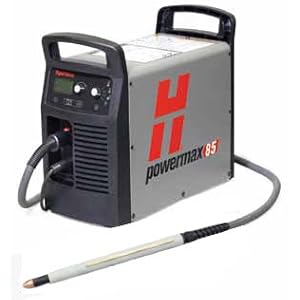
after lots of research i went ahead and ordered an Hypertherm powermax 85 with CPC and machine torch. this gives me 2 weeks to get everything up and running before i have the plasma unit delivered.
-
08-11-2011, 01:15 AM #29
Registered
- Join Date
- Apr 2011
- Posts
- 0
i have ran into a few problems with parts i bought pre-built for this system
 not the end of the world type of problems, just slowing me down to an crawl.
-
08-11-2011, 06:49 PM #30
Gold Member
- Join Date
- Jul 2005
- Posts
- 2415
If it's anything with our electronics I assume you have already contacted us or have engaged me on the CandCNCSupport Yahoo Forum.
TOM caudle
www.CandCNC.com
-
09-08-2011, 05:03 AM #31
Registered
- Join Date
- Apr 2011
- Posts
- 0
got upset trying to get the system running last month and spent the end of summer outdoors.
starting today i went over everything and cant get past the same problem. once i get everything loaded and try to open mach3 using the CandCnC dthc icon on the desk top i get an error saying something about how my stepper motors are tuned too fast for the 45000 blah blah.......... i read and read but cant figure out what this means other than i cant get past the point of trying to setup the DTHC2 part of the manual. if i open mach3 from the start menu i can jog the motors just fine. but using the icon created on the desk top after loading the files on the support CD specific to mach3 i get this error. i haven't made any changes to anything yet in mach3 so this is makes it even more confusing.
i feel the learning curve kicking me in the face.
-
09-08-2011, 04:01 PM #32
Gold Member
- Join Date
- Jul 2005
- Posts
- 2415
The Kernel Speed is preset in the profile to 45000 hz. What it's trying to tell you is that you have the velocity (motor tuning) on one or more axis set higher than MACH can send pulses using 45000 hz. All you need to do is go past the error and change the velocity down. Set it temporarily to some low number until you get the axis calibrated (steps per unit) and THEN you can deal with the proper velocity and acceleration settings. The first axis to look at would be Z because it normally has a much higher Steps per Unit setting.
Steps per unit increases for an axis the finer the final drive resolution. Think about a set of stairs. The distance you have to go is the same. If you have to get from the bottom to the top in 3 seconds how many Steps per second do you have to execute to get there? What if we made the stairs (steps) closer together? We now have the same distance to go in the same 3 seconds but now we have to execute more steps. What if we just can't move our feet fast enough to get the speed and distance? Then we "error" off.
As you can see from the physical example we can fix it by:
slowing down the velocity (take longer to get tot he top of the stairs). or changing the number of steps. In the real world the number of steps is cast in stone based on the "gearing" and the motor. That of course is dependant on YOUR particular table design.
If MACH refuses to load and run then your PC you are trying to use is too slow to handle 45 KHZ.............get a faster PC of contact me and I can provide you with a MACH profile that uses a 25KHZ default kernal speed. That may cause you problems at reaching decent speeds on Z if you are using a finer pitched leadscrew setup.
Here is some math:
To spin a stepper motor using a Gecko microStepping drive you have to send it 2000 steps per revolution (360 deg). So to move the load 1 inch you have to determine how many times you have to spin the motor based on the gearing. With R & P the number is typically low because of the nature of the pinion gear multiplying speed. On the leadscrew (like on the Z) it is the opposite. You have the spin the motor more times to move the same distance. A 10 TPI (threads per inch) LS takes 10 turns to move 1 inch.
Simple math then dictates if it takes 2000 steps for ONE it will take 2000 X 10 = 20,000 steps to spin the leadscrew 10 times. If you have to (want to) move the load 100 IPM (1.666 inches per second) then you have to send 20,000 per second to move it 1 inch in 1 sec or 33,320 steps per second to move it 1.666 inches in 1 second. If you ask MACH to send 33,320 steps per second and the kernel is set to 25,000 per second then it barfs and gives you the error/ It is saying " I can't do what you are asking me to do"
There is no escape from the numbers. It is a basic issue every table builder must face. If you buy the table/gantry as a kit the vendor should be able to provide you with recommend settings.
Trying to get other functions to work before you can get basic calibrated motion is nothing but an exercise in frustration.
The profiles we send are all setup for use with the hardware. There are a lot of settings that if not exact will cause the whole thing to be unusable. A default MACH profile WILL NOT WORK without extensive changes in the configuration. It's not as simple as just change a couple of pin settings or the screen set and it will start to run.
-
09-09-2011, 04:33 PM #33
Registered
- Join Date
- Apr 2011
- Posts
- 0
thanks for the tips, i have never dealt with mach software so its a lot to handle between reading all the info i can and trying to implement it into the new system all at once.
i hope this weekend to get things tuned and running properly.
-
09-09-2011, 04:51 PM #34
Gold Member
- Join Date
- Jul 2005
- Posts
- 2415
The CandCNCSupport Yahoo group is a good source for support on our products and is monitored weekends. Other users will often jump in and help too.
TOM caudle
www.CandCNC.com
-
09-10-2011, 01:17 AM #35
Registered
- Join Date
- Apr 2011
- Posts
- 0
question for anyone who knows a thing or two about mach3, how do you re-size the screen or add an slide bar or something? i see there are readouts off my screen but cant get the screen to scroll down or to the right so i can see them. i have an 19" monitor and even with mach3 maximized there are things running off the screen. i have been searching the web for info about adjusting the screen size in mach3 but had no luck yet.
thanks
-
09-10-2011, 05:51 AM #36
Registered
- Join Date
- Jan 2006
- Posts
- 33
This is one of the many reasons I really despise Mach3. Aside from the typically horribly cluttered interface, you have to make (or hope someone else has made) a whole new "screen set" for each resolution you want to use. I don't know who thought it would be a good idea to use all fixed-width elements on a user interface for a piece of software that will be used on multiple different resolutions, but that person really needs a swift kick in the shins. Originally Posted by tig-racer
Apparently, there is some sort of "Auto Enlarge" option somewhere that will resize all the buttons and whatnot to fit the screen, but knowing Mach, I'd be surprised if it worked properly.
I would recommend switching to EMC2 but you are using CandCNC stuff and their EMC2 drivers appear to be vaporware. (This is why I plan on replacing my CandCNC THC with something else, so I can leave the joke that is Mach3 and switch to EMC2).
-
09-10-2011, 03:52 PM #37
Registered
- Join Date
- Jan 2011
- Posts
- 0
I just changed my screen resolution until Mach3 fit properly. Since I don't use the computer for anything else, it didn't bother me.
Carl
-
09-11-2011, 01:35 AM #38
Registered
- Join Date
- Apr 2011
- Posts
- 0
awesome, i have my monitor turned up all the way and still cant see everything. ill worry about that later.
onto more fun, i am trying to get things into an position they will be ready for an dry run. so far i have the system "i think" calibrated but, the DTHC is pushing the torch into the work surface and not returning after triggering the contact switch. i can see the switch working properly in mach3 but im not able to get past this problem.
im about ready to pay for an class or 2 on this mach3 software, i cant make any headway getting the system setup on my own. not sure if i am missing some literature or if i have all the literature released and its just missing a few key details.
not sure what to do at this point, system is on and able to jog properly but im not able to get the DTHC to work leaving me dead in the water. ive read the manual 5x's today alone and all seems well but when i load an file made with sheetcam the torch is pushed into the work surface and drug around.
-
09-11-2011, 04:07 PM #39
Gold Member
- Join Date
- Jul 2005
- Posts
- 2415
Originally Posted by tig-racer
Change the monitor resolution in the Windows The screens are built to optimize at 1024 X 768 (a standard VGA resolution). If you run the monitor at that or something higher then everything fits on the screen, Auto sizing is not the answer. Running the right screen resolution in Windows is.DISPLAY on the Control Panel
-
09-11-2011, 04:55 PM #40
Gold Member
- Join Date
- Jul 2005
- Posts
- 2415
Originally Posted by tig-racer
If it all works like is outlined in the manual (touch-off sequence, rise to pierce height and fire then lower to initial cut height) and you get acceptable results on a manual cut (THC Button OFF) THEN the problem has to be either the code itself or a motor tuning issue.
The auto install we send does 90% of the setup for MACH. We can't predict what the motor tuning will be so setting that and making sure all the axis move exactly the right amount and speed is a process that has to be done on the specific machine.
You really don't have to get real deep into MACH unless you really want to . There is a MACH manual on the CD but it will tell you how to build a watch when all you need is to know what time it is. The WORST thing you can do is to start dinking with settings without understanding what they do or what role they play with specific hardware. If you MUST dink then copy and rename the default profile we load using MACH Loader (clone process) and then you could get back to a default easily.
If the motors are tuned and calibrated right (and that means it works and moves the correct distance with simple G-code commands) then it's time to read the DTHC manual one more time. Concentrate on the section about using the Z (torch) as the touch off. It as to do that sequence perfectly every time or you start out at the wrong height and everything will go downhill from there.
Your whole problem may be the way you are using SheetCAM but until you confirm everything in hardware is calibrated and runs right then you can't focus on the area to make it work.
Run the tests on the hardware. We went to great pains to put in automated self tests on the DTHC side. If something fails STOP. We need to address that before you try to go on. If it all passes the electronic self tests THEN move to the setup of the touch off (2-3 pages in the manual).
The section on doing a manual cut with the arc gap set correctly and observing the actions and indicators will point to a place to start the final troubleshooting.
TOM caudle
www.candcnc.com

 Reply With Quote
Similar Threads
-
PrecisionPlasma/CandCNC 5X10 table build
By Teknition in forum Waterjet General TopicsReplies: 123Last Post: 04-01-2013, 08:34 PM -
CandCNC thc with industrial plasma (hypertherm ht2000)
By DanOSB in forum Waterjet General TopicsReplies: 5Last Post: 10-26-2011, 09:02 PM -
DIY 4 x 4 CNC PLASMA TABLE (NO ELECTRONICS)
By rchacich in forum News AnnouncementsReplies: 0Last Post: 10-24-2009, 04:27 PM -
CNC plasma electronics and software
By elektrokontakt in forum Work Fixtures / Hold-Down SolutionsReplies: 5Last Post: 01-12-2008, 05:49 PM -
Cnc plasma electronics
By Thump3r in forum Waterjet General TopicsReplies: 0Last Post: 12-18-2007, 01:45 AM
