


Hi all, I am assembling my unit now and changes have been as discussed by others that of having base same size each side and x rails same height. I also canterlevered out the rails with none of the machining of the left and right side inner panels. I also added an extra left and right top plate to give more thickness up there. Because I am building here in NZ most stock is metric so some measurements are a bit different. Luckily our 3/4" square aluminium was still 3/4 square from old dies. i used stainless steel 304 for rails and had to fabricate from steel the z nut mount and the z stepper mount. The gantry is from steel RHS lightened into a girder form. Lookls good so far and am looking forward to "blast off".
Rayna
Thread: Mods and Upgrades
Results 21 to 37 of 37
-
07-04-2011, 10:28 PM #21
 Registered
- Join Date
- Jul 2007
- Posts
- 36
-
07-08-2011, 09:00 PM #22
Registered
- Join Date
- May 2011
- Posts
- 24
Bill - I'm curious about the carriage bolt mod you did on your first machine. Did you really go with 4 x 5/8" bolts? Did you increase the size of parts 16, 22, and 23 to accomodate that large of a hole, or maybe it was really 5/16" (the size I'm planning)? Did you need to countersink those? I can't tell from the plans if cap heads would interfere with the Z axis. Thanks!
-
07-08-2011, 10:58 PM #23
Registered
- Join Date
- Apr 2011
- Posts
- 0
I used 5/16-18 cap heads, sorry if there was a typo in another thread. The cap heads fit nicely in the already countersunk holes without needing any further machining if I recall correctly. The one bolt behind the lead screw I used a standard bolt because the lead screw was in the way of the allen heah otherwise and I wanted to be able to torque it down once all was together. The second carriage mod I did I used allthread and did not use countersinks in the 4 locations. I wanted more thread to glue to. Originally Posted by cgodwin

Hope this helps...
billj
-
10-21-2011, 05:28 AM #24
Registered
- Join Date
- Mar 2011
- Posts
- 144
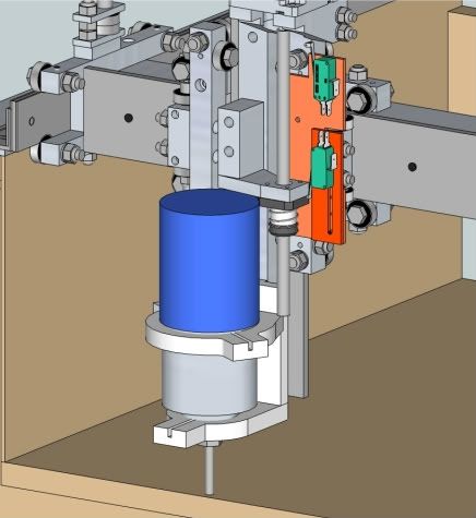
I'm working on new mount for Bosch Colt , its going to be out of aluminum and will have small rail on the back so its easier to square it and it won't move/twist when cutting. its not done yet I still have to finish up upper clamp (have to cut it in half and make little ears for srews) but this will give you idea how it will look.
let me know any comments.
-
10-21-2011, 05:45 AM #25
Registered
- Join Date
- Aug 2011
- Posts
- 215
I just got my Colt in the mail today and was thinking about clamps. I was also thinking of clamping onto that smaller diameter right above the collet just like you pictured, but there are some features in the way that will prevent this. I measured the clamping area is 2.75" dia by 2" length, but really only 1.5" length is useable if you want to be able to push the red collet lock button. I'm curious to see what you end up with. I'm not yet at the point where I need to make clamps, but I'll be there pretty soon. Originally Posted by fastpcuser
-
10-21-2011, 05:52 AM #26
Registered
- Join Date
- Apr 2011
- Posts
- 121
fastpcuser, Looks good. I know you asked about my mount, but I haven't had a chance to do much about it. Your concept is similar though. I have to rebuild my computer as the HDD died, so my machine is down for a while. I may have time this weekend to share my thoughts though.
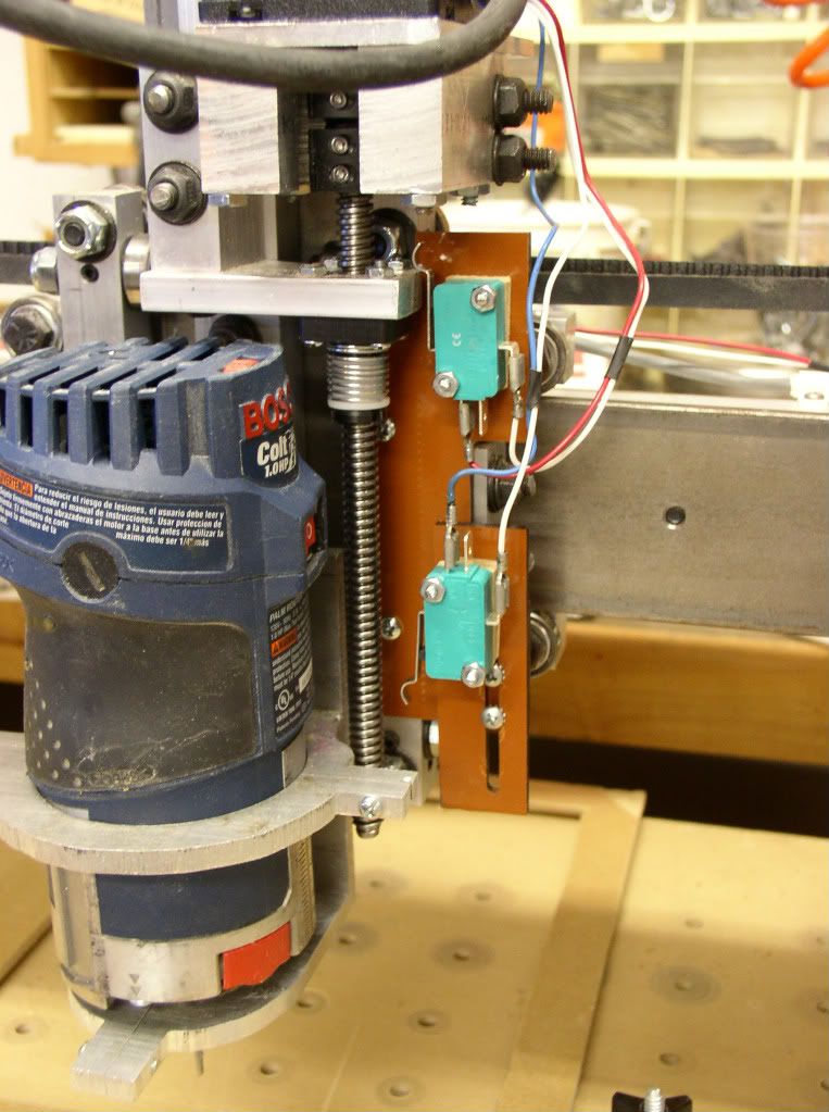
GT, the nose is a usable clamping area which extends the distance between clamp rings. This mount is just hacked out of 1/4" plate with a bandsaw. Works but needs refinement. Its based on a commercial mount for some other machine. You can see the router doesn't drop all the way down onto the lower mount due to the various protrusions, but it clamps up.
-
10-23-2011, 07:43 PM #27
Registered
- Join Date
- May 2011
- Posts
- 21
I planned to use a Kress spindle https://www.cnc-plus.de/product_info...j51gd013hrbk86 but its 25cm long and 7 cm in diameter. Its imposible to mount this since there is no room available. First changeg would be to make slimmer the piece that connect drive screw to Z axis. Second problem is the holder. The spindle is holded using one aluminium piece like https://www.cnc-plus.de/product_info...j51gd013hrbk86 but again this can't be mounted. Third problem is the mounting the Z axis motor itself. We might need a longer z axis cariage part to allow mounting the motor upper. Does anyone tried to do something like this? Or any suggestions on how to mount it?
-
10-23-2011, 09:10 PM #28
Registered
- Join Date
- Apr 2011
- Posts
- 121
Considering how the X-axis nut is located, you really need to use a two piece mount and load the spindle from the front. But, it would be easy to draw and cut out a mount for that spindle. Originally Posted by ldanut
The bigger problem is getting the z-axis nut bracketry out of the way. What you could do is integrate the z-axis lead screw nut into the router bracket. I don't know if you can still get the body of the spindle around the stepper motor though. I have no idea if this would really work.
-
10-25-2011, 02:55 PM #29
Registered
- Join Date
- Apr 2011
- Posts
- 121
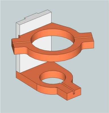
Here are a couple of Bosch Colt mounts. They are not completely thought out yet, and if you have any comments/critique let me know.
The basic dimensions are the same as my quickly hacked out mount above except that the router is moved away from the gantry another 0.125 inch for bolt head clearance.
The first one is very similar the the hacked out one, but the upper mount clamps are rotated 45 degrees similar to the one in the plans. I dont really think that matters though. The grooves in the mount are there to represent cut lines for pinching the clamps together. I'm thinking of cutting the vetical part down and eliminating the dado for the top bracket. I'm also thinking of eliminating the stepped back, narrowing the mount and fitting it between the ball bearings. It would be easier to make if I do that.
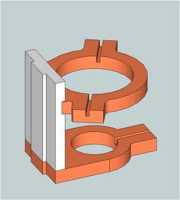
The second concept is very similar to the first except I moved the acme nut down to the top mount of the router. The post above about using a taller spindle got me to thinking that the nut bracket could be redundant. this concept allows for a taller spindle. I still think that user has problems with hitting the stepper motor, but I did not model his spindle to check clearances.
-
10-25-2011, 03:15 PM #30
Registered
- Join Date
- May 2011
- Posts
- 21
Thanks for your drawings. Look very nice. What software did you use to model them?
My solution would be to make a slimmer bracket for acme nut and mount to nut from behind of acme thread. I will use a .375 aluminium plate that connect the Z rail block with a modified nut plate. It will move between those two ball bearing bolts. I think my spindle requires only one thicker holder and I will use your idea with using another plate that its mounted on Z block. The spindle requires 10inch of space and I can acomodate this with the plate that is bolted to Z block moving it down so it doesn't colide with stepper motor.
-
10-25-2011, 03:52 PM #31
Registered
- Join Date
- Apr 2011
- Posts
- 121
I'm using Sketchup. Its really not appropriate as it is a surface modeler and not a solids modeler. It produces good pictures, but cannot be used to create CNC ready parts.
I do not know if your design will work without seeing what your ACME nut mount looks like. I think it would be too small and too flexible if you cut away enough to get behind the spindle. I am still concerned that the body of the spindle will not pass by the stepper. Of course, you could offset the spindle to the left to compensate.
I would probably use 1/2" (13mm) material instead of 3/8" just to get more material on the edge in which to insert the screws as you make your mount.
-
10-25-2011, 07:31 PM #32
Registered
- Join Date
- Apr 2011
- Posts
- 121
I took a few minutes over lunch to model up a rough idea of the Kress spindle. It looks like it will definitely hit the stepper motor attachment. Getting a way to attach the acme nut will be problematic unless you build it into the mount some way.
This is just a rough idea based on the maximum dimensions published in your link.
-
10-25-2011, 10:01 PM #33
Registered
- Join Date
- May 2011
- Posts
- 21
Thanks for all your support. Did you model the entire CNC in Google Sketchup program? It looks you are very fast at doing this
 . I will try to model something my self but it will take a while until I get used to.
There is any issue if the spindle holder mounts the spindle far enought from Z block so there is room for Z motor and drive screw nut bracketry? I guess it will vibrate like hell.
-
10-25-2011, 10:43 PM #34
Registered
- Join Date
- May 2010
- Posts
- 93
Without looking at the plans right now (dont have access at the moment), is there a way to move the z axis to the backside of the z plate? Seems that could solve the Kress Spindle from hitting the z motor mount?
-
10-25-2011, 11:15 PM #35
Registered
- Join Date
- Apr 2011
- Posts
- 121
Yes, I did model the entire thing. Since I intended to do some changes, I felt it best to test them in software. I'm only half-fast. As you can see, I just modeled the envelope. Since the spindle is curved, it will not be as close to the ACME screw as shown. But, its still leave no room for the ACME nut in the original position. Originally Posted by ldanut
If you wish to use SketchUp, download and take time with the tutorials. Otherwise, you will not get very far, very fast.
Incidently, I am more than willing to share any designs I create in skecthup. However, I cannot share the basic machine model. It would be a violation of Bob's intellectual property.
It might vibrate, but more importantly, it decreases the stiffness of the Z axis resulting in poor performance. It also increases the load on the Y carriage parts and the design would likely not support it. Originally Posted by ldanut
-
10-26-2011, 01:21 AM #36
Registered
- Join Date
- Oct 2004
- Posts
- 590
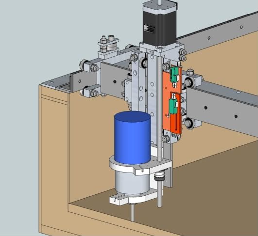
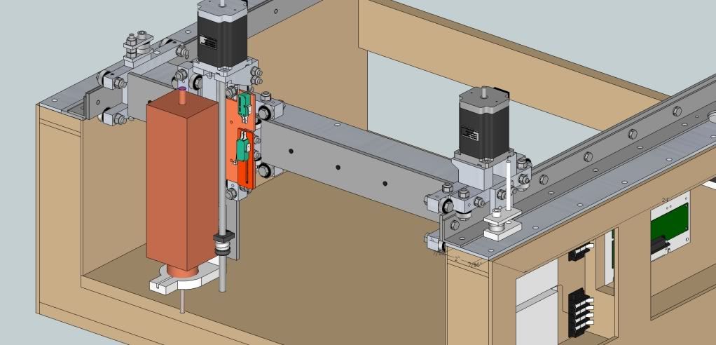
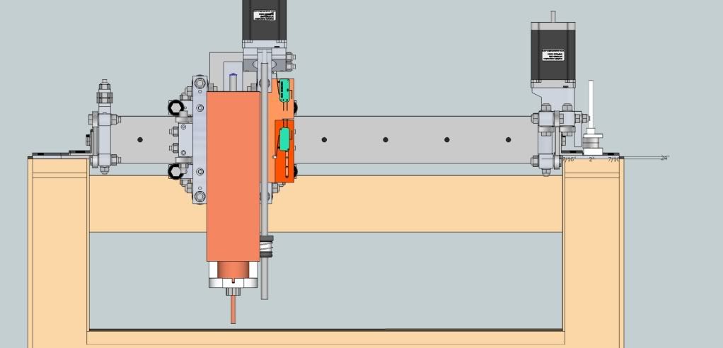
Flip the stepper over and put it on the backside of the Z rail with the nut and screw above the Y rail. Some concept renderings below. Makes a tall Z axis but the weights remain close to the rails for rigidity. Originally Posted by ecurb5
Chris
-
11-06-2011, 07:17 AM #37
Registered
- Join Date
- Mar 2011
- Posts
- 144
Just Got good deal on ebay for THK Rails with blocks so I'm thinking I'll be making new machine and using those instead of bearings.

 Reply With Quote
Similar Threads
-
JSM 40U Upgrades
By Nobodyspecial in forum Laser Engraving / Cutting Machine General TopicsReplies: 4Last Post: 08-27-2010, 07:09 PM -
New Win xp.. Do I need upgrades?
By jaru-eri in forum Mach Software (ArtSoft software)Replies: 1Last Post: 03-06-2009, 04:56 AM -
ElDorado upgrades
By sstec in forum Shopmaster/ShoptaskReplies: 1Last Post: 11-29-2007, 08:49 PM -
Any rhino upgrades
By slpd in forum Rhino 3DReplies: 18Last Post: 08-02-2007, 07:20 PM -
Bob-art and other upgrades.
By Scott V in forum BobCad-CamReplies: 10Last Post: 02-18-2005, 10:15 PM
