


Have a Tornado 200 and did a spindle alignment test cut on a 3" dia piece today. Got 2.953 on the far side and 2.950 on the chuck side. Cut was 5" long and got .003" run out. I don't have a manual that describes the adjutment procedure but I did pull the front cover off and found 2 sets of bolts on the motor end, the other side of the spindle block has the interior cover attatched to it. Is this a jacking bolt adjustment or a shim adjustment?
Thanks,
H
Thread: Spindle alignment
Results 1 to 11 of 11
-
05-29-2011, 12:14 AM #1
 Registered
- Join Date
- Jul 2005
- Posts
- 179
Spindle alignment
-
05-29-2011, 07:59 PM #2
Registered
- Join Date
- Jul 2005
- Posts
- 179
OK, got to this point
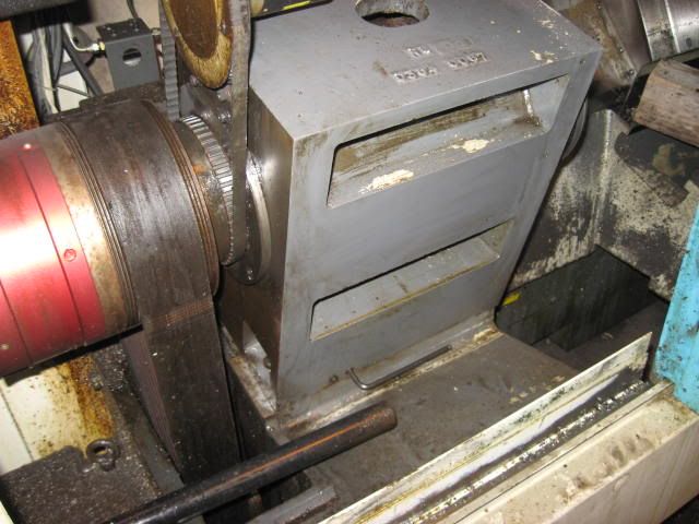
There are two allen head set screws on the lower left front of the spindle base as seen in the top picture. In the manual on the base frame is shows an "adjusting block" in this area on the frame. There is a gap between the spindle casting and frame casting under these screws. I took the left screw out and it has a machined end on it. There are two allen head bolts on each corner of the spindle casting and the spindle is belt driven.
It's taken a while to get to this point and apparently I'm going to have to put the chuck back on to make another test cut after any adjustments. Unfortunatley, the covers will not go back on the machine with the chuck in place, and you can't get to the base bolts with out the cover removed.
1. Should the drive motor be loosened up to make any base adjustments?
2. Shifting the spindle base on its mounting pad does not make a perpendicular move with the X axis. How to you take out a taper unless you have a jacking bolt or shim the spindle?
:drowning:
Thanks,
H
-
05-31-2011, 12:04 PM #3
Registered
- Join Date
- Mar 2010
- Posts
- 0
Hi HMC710
1. Yes, the drive belt does need to be loosened off before adjusting the head.
2. Cut and test to get the desired parallel tolerance for the amount of tool pressure you will be applying when taking your usual finishing cut. The bigger the cut the more push off. Use the 2 allen screws bottom left of the headstock to pivot the head and remove any unwanted taper from the finished turning. One of the allen screws pushes and the other pulls the headstock to move it around the pivot. A tip is to leave a little nip on the bolts top right where the pivot pin resides, slacken off all the other bolts.
-
05-31-2011, 02:23 PM #4
Registered
- Join Date
- Jul 2005
- Posts
- 179
Pivot Pin
Thanks 600,
Pivot pin is located upper right then?
Just got the chuck back on and getting ready to dial it in so I can make a cut. (then take it all back off so I can put the panels back on.......)
Thanks,
H
-
05-31-2011, 03:08 PM #5
Registered
- Join Date
- Mar 2010
- Posts
- 0
That is correct. As you look at it from the front of the machine. Originally Posted by hmc710

-
06-02-2011, 04:55 AM #6
Registered
- Join Date
- May 2006
- Posts
- 82
Hi H !
do you have this job done ?
-
06-02-2011, 11:35 AM #7
Registered
- Join Date
- Jul 2005
- Posts
- 179
Hey cncatj! How are things down South? Almost done, lined it all up with a few tenths of taper in 5". Pulled the chuck back off cleaned all the gunk off guards up and put them back on the other night. Now its just truing up the chuck again. I played around with different distances that the hydraulic jaw actuator was screwed on, I lost some travel the first time I put it back on. I was hoping to get it all done yesterday but spent all day doing eng drawings and cutting parts on the table. Once I get the chuck dialed in I'll clean up the guards with some 409 and check all my offsets. Then its on to tail stock alignment......:banana:
A big thanks to all the help out there in cnczone land!
H
-
06-03-2011, 10:21 PM #8
Registered
- Join Date
- May 2006
- Posts
- 82
Things are quite good Here H !
It's good to hear that your machine is almost finished ,
I'm now taking a turret all apart !!
Puting all new Orings & seals
-
06-03-2011, 10:56 PM #9
Registered
- Join Date
- Jul 2005
- Posts
- 179
Good luck with that, I'm hoping I won't have to do that anytime soon. Got tailstock aligned and cut true for a few pcs then got some taper back. Changed out my cutting insert and will try another cut. Is there an adjustment on the hydraulic pressure on the turret? Mine seems to slam hard into position, I'm just not that much in a hurry. Also can the coolant flow be adjusted down?
Thanks,
H
-
06-07-2011, 05:38 AM #10
Registered
- Join Date
- May 2006
- Posts
- 82
Sorry for the delay H ,
About your turret issues , The slam in my opinion can be caused by several reasons:
1-The shock absorbers , Does the turret slams in both directions ?
2- Not enough lubricant inside the turret ,Duplomatic suggest a special type of lubricant
also about the coolant flow , I'm not sure if the flow can be adjusted down ,
by simply rotate the coolnt disc , H , P.M your email adress
-
06-07-2011, 12:23 PM #11
Registered
- Join Date
- Jul 2005
- Posts
- 179
I've only seen the turret go one direction. Shock absorbers? Will check into the lube. My turret has drilled balls where the coolant comes out. PIA to adjust or control. PM sent.
H

 Reply With Quote
Similar Threads
-
Spindle alignment
By fastpcuser in forum Momus Design CNC plansReplies: 4Last Post: 05-27-2011, 03:15 PM -
Need Help with Spindle alignment!
By Darian S in forum DIY CNC Router Table MachinesReplies: 19Last Post: 10-26-2010, 03:04 AM -
Spindle Alignment
By forrest39 in forum Benchtop MachinesReplies: 9Last Post: 08-03-2010, 11:36 PM -
Toolchanger/Spindle Alignment
By lovell110 in forum Haas MillsReplies: 3Last Post: 06-15-2007, 12:26 AM -
Spindle is out of Alignment
By Crashmaster in forum Uncategorised MetalWorking MachinesReplies: 2Last Post: 04-05-2007, 04:32 PM
