


found this one HK-3026-880KV Scorpion Brushless Motor For Protos
just to give you a rough idea on whats out there.
Specifications
Stator Diameter ............................ 30.0 mm (1.181 in)
Stator Thickness ........................... 26.0 mm (1.024 in)
No. of Stator Arms ................................................ 12
No. of Magnet Poles ............................................... 10
Motor Wind ............................................ 10 Turn Delta
Motor Wire ..................... 14-Strand 0.25mm (30 AWG)
Motor Kv ............................................. 880 RPM / Volt
No-Load Current (Io) ................... 2.30Amps @ 6 volts
Motor Resistance (Rm) ............................. 0.026 Ohms
Max Continuous Current ............................... 52 Amps
Max Continuous Power .............................. 1450 Watts
Weight ......................................... 199 Grams (7.02oz)
Outside Diameter .......................... 37.5 mm (1.476 in)
Shaft Diameter ............................. 5.00 mm (0.197 in)
Body Length ................................. 48.4 mm (1.906 in)
Overall Shaft Length ...................... 74.2 mm (2.921 in)
Results 21 to 40 of 148
-
06-11-2011, 11:08 PM #21
 Registered
- Join Date
- Oct 2006
- Posts
- 120
-
06-12-2011, 03:39 PM #22
Registered
- Join Date
- Apr 2009
- Posts
- 165
Ive heard ood things about the Scorpion motors. Im a big fan of Neu motors
Welcome
They have a line of Heli motors that have internal fans to help cool them. They are pretty pricey though.
Eric
-
06-12-2011, 05:44 PM #23
Registered
- Join Date
- May 2010
- Posts
- 118
Brushless RC Motor Ratings
RomanLini,
I'm not sure what the source for your data is, but you may want to do some more research. The motor is this airplane is an e-Flite Power 160. Rated at 2700 Watts burst (37V at 75A), 2200 Watts continuous.

My own direct measurements confirm those numbers. Swinging a 22x10 prop and running on 10 fresh 5000MaH LiPo's (36.8V on the meter) it peaks out at just over 2700 Watts drawing 75 Amps. I'd say that is pretty accurate. I cannot say how much of that energy is lost as heat, but I can say performance is certainly equivalent to a two stroke 1.6c.i. engine putting out 3.7 rated hp (2759 Watts). I have to believe that efficiency is in the 80 to 85% range based solely on the motor's demonstrated ability to haul this very draggy, 22lb. air-frame around with authority.
Regards,
Randy
-
06-12-2011, 08:08 PM #24
Registered
- Join Date
- Oct 2005
- Posts
- 2392
Thanks Eric I appreciate your knowlege and the offer to help! I won't have a lot of time for checking this out this week but I did look over some motor and driver stuff online today. There are some impressive motors out there! Originally Posted by tskguy

I understand the RC pulse system quite well as I have worked with hobby robotics in the past using RC servos under computer control. It would be good to know more about this "arming" feature. Is it as simple as turning on all the power then applying a short period (a second?) of HI (2mS pulse)? Does the motor spin up when arming?
Also other info that would be useful is RPM curves vs input pulse. I'm not sure how sophisticated the ESC drivers are, mainly; do they keep the motor at a constant RPM for a constant pulse control? Or does the motor speed "sag" under load similar to DC traction motor? There could be awkward issues with PID control with 2 controllers in the closed loop...
Also any more info on the typical RPM range from a ESC controller, from 1mS to 2mS pulse control?
And what kW range do people really want? Considering a 1kW 50 amp DC supply will be very expensive in itself, plus motor plus ESC controller that's going to get pricey. Maybe something around 500W brings the prices right down and even 250W is still way overkill for engravers.
Groswald- That's an impressive 22lb plane! I can see why these motors are popular with their good torque at all revs, the comparable 2-stroke motor would have a very peaky powerband.
Thanks Fish4fun and everyone who provided motor info. I'm still soaking this up...
-
06-12-2011, 11:47 PM #25
Registered
- Join Date
- Dec 2008
- Posts
- 292
Maybe I can answer some of your questions.
It would be good to know more about this "arming" feature. Is it as simple as turning on all the power then applying a short period (a second?) of HI (2mS pulse)?
Arming works a little differently in various controllers. But, basically, with most of the 'standard' controllers, the controller will not arm until it sees a pulse width of less than 1ms. After it arms, the control range is 1.0 - 1.8 ms unless you program the controller with different end points. Some controllers can be programmed, some can't. Some smaller, less expensive controllers expect to see full throttle, then low throttle to arm but that isn't how most work.
Does the motor spin up when arming?
No, not on normal controllers, it is a built in safety feature preventing 'runaways'.
Also other info that would be useful is RPM curves vs input pulse. I'm not sure how sophisticated the ESC drivers are, mainly; do they keep the motor at a constant RPM for a constant pulse control? Or does the motor speed "sag" under load similar to DC traction motor?
Some controllers have a 'governor mode' but it is not very flexible, it is more of a fixed constant speed, typically used for helicopter for 3D aerobatics. The motor would 'sag' as additional load is applied. For RC airplane use the load is pretty constant since we are not changing the pitch. For helicopters, the load changes significantly. I would think the load from a milling bit (except for large bits in metal] would be pretty constant based on a constant feed rate, but I could be wrong in my assumption.
Also any more info on the typical RPM range from a ESC controller, from 1mS to 2mS pulse control?
The rpm range will be determined by the kV rating of the motor and the voltage of the power supply. For a motor with a kV of 1000 and using a 12V supply, the max rpm would theoretically be 12,000 rpm.
And what kW range do people really want? Considering a 1kW 50 amp DC supply will be very expensive in itself, plus motor plus ESC controller that's going to get pricey. Maybe something around 500W brings the prices right down and even 250W is still way overkill for engravers.
Since 12V or 24V supplies are readily available, even in larger max amp supplies using server power supplies which are very cheap to by on ebay, we would probably need motors in the 600-900 kV which would yeild 0-20K rpm approx.
Hope this helps with your questions.
Don
-
06-13-2011, 01:39 AM #26
Registered
- Join Date
- May 2010
- Posts
- 118
RomanLini,
Thanks. It was quite a project, and my first electric. I have to say that I am quite impressed with the capability of such a small powerplant. Now, if the batteries would just come down in price!
Regards,
Randy
-
06-13-2011, 04:00 AM #27
Registered
- Join Date
- Apr 2009
- Posts
- 165
Hi all,
Here are a few of my thoughts to Romans questions. First off let me explain what difficultys I have with my current setup and also how I think the super PID will help. Currently I have a Castle Creations 100amp controller its not a High Volt one so the max volts is maybe 16v. Anyway the way Im currently using the controller is by using the built in gov mode for helis. I am doing this to try and keep the cutting rpm constant. It actually does a great job but doesnt kick in until after 50% throttle. So my RPM choices are very limited. Im also never sure of what the rpm is so speeds and feeds are tuff to get right.
What I envision for the super PID is setting the controller to airplane mode which is basically a linear rpm curve. It would also allow the use of cheaper ESC's. Then use a tach feedback like the super PID to hold spcific rpms.
Would that work? Oh I forgot to mention, I actually gear down my motor to the spindle, Similar to a mill head. I assume the gear ratio would also be a key component. I may be in the minority for that requirement, my machine is designed for milling aluminum and brass. Thought I would throw that out there.
Here is a link to my spindle, it has some pics of my first motor. I have replaced it with a larger outrunner sence then.
Eric
http://www.cnczone.com/forums/diy-cn..._complete.html
-
06-13-2011, 07:34 PM #28
Registered
- Join Date
- Mar 2007
- Posts
- 217
I do not have any first-hand knowledge of the ESCs used with these motors, but I have done some reading, and the reading appears to present some contradictions. The motors themselves have specifications implying RPM is directly related to input Voltage (KV = K rpm per Volt). This seems straight-forward enough; however, these motors are permanent magnet, 3 phase motors, which implies that the RPM is tied directly to the frequency of the drive signal (Output of the ESC) and number of poles, and should have little to do with the DC input voltage applied at the ESC input. This, of course, led me to more reading and some thinking. Finally a little bell went, "ding ding" in my head, and I think I understand how/why these seemingly conflicting viewpoints on the motors and their ESCs actually come together :-)
First thing is to throw out every preconception you might have from working with conventional industrial VFDs and 3 phase motors. A lot of information is in the name "Brushless DC Motor".
In a conventional Brushed DC motor the commutator alternately energizes some number of coils, and the amount of current that is drawn is dictated by the supply Voltage, the winding Inductance, the winding Resistance and the period of Time any particular coil is energized. For any given Voltage the physics of the motor dictates a "no-load RPM". From this base-line maintaining any particular RPM at any given load is handled by increasing or decreasing the Voltage, and the torque at any given RPM is limited only by the motor's ability to handle current and your speed controller's ability to supply current. Pretty straight-forward.
A conventional 3-phase VFD provides a 3-phase signal to a 3-phase motor. The motor rpm is directly linked to the frequency of the drive signal. The amount of current required is dictated by "rotor slip". Rotor Slip is a measurement of the phase angle difference between where the rotor "should be" vs where it actually is. Under no-load conditions there should be very negligible slip, as the load increases, more current is required to keep the rotor "where it is suppose to be", and the "slip angle" increases. The ability of a 3-phase motor to provide torque at any given RPM is dictated (much like the brushed DC motor) by the current capabilities of the motor and the Supply.
With the RC BLDC motors and ESCs things are a bit jumbled. The required RPM output margin for error is quite large, so the expense of a true VFD is not requisite. In the RC BLDC's design 2/3s of the coils are energized at any given time, the other third of the coils are used to provide timing information to the ESC. Each set of coils takes a turn being the "sensor". The ESC itself is a simple PWM current regulator, and it doesn't care how much time is spent supplying that current to a particular set of coils, only that at particular positions in the shaft rotation that it changes which coils are energized. In this it is much like the commutator in a conventional Brushed DC motor. We don't need to know anything about how the ESC achieves current limiting or shaft position sensing to take control of it; we simply need to add a shaft postion sensor to monitor RPM and then adjust the "throttle position" in the ESC to increase or decrease RPM/Torque. Our ability to regulate speed will then become a question of ESC response time. Unlike a conventional VFD, the ESC does not have a "target frequency", rather it simply "responds" based on the shaft sensing. That is, the Voltage/current can be increased w/o a corresponding increase in RPM.
While it would be ideal to design an ESC from the ground up for our purposes, this could greatly increase the cost. Experimenting with various ESCs and testing their response time is likely to prove the least expensive approach. Assuming a single shaft sensor and 10,000 RPM, this would imply a uController would get new RPM data at 10uS intervals. The ESC interface is most likely controlled by a standard RC pulse width controller, so it responds to pulse widths from .5mS to 2mS every `20mS. This means that up to 2000 RPM samples could be averaged between adjustments to the ESC, and that up to 50 speed adjustments could be made per second.
While 50 adjustments per second might prove adequate, a dedicated design has the potential to greatly improve the feedback loop. Perhaps some of the ESCs use FLASH based uControllers and could be re-programmed via JTAG. (Did some checking, here is an excellent link on controlling an ESC via I2C/TWI! : Converting TowerPro 25A type 2 ESC's from PWM to TWI/I2C control - RC Groups ). In a casual browse through the ESC link (1149 posts!), it appears that everything we might want to do to these ESCs has been done! It appears many of the "older" ESCs used an atmega8 uController, while many of the "newer" ESCs have moved to Silabs based processors (formerly Cygnus). Both processor families are well documented and easily re-flashed. The RC hobby folks are extremely weight conscious, so it might be reasonable to port the same basic design to a larger DIY PCB with heat sinks and larger FETs. I am certain any commercial attempt at selling "borrowed" designs would end badly, but DIY PCB's for the CNC crowd would likely not ruffle too many feathers. It all looks very promising.
Fish
-
06-13-2011, 08:11 PM #29
Registered
- Join Date
- Apr 2009
- Posts
- 165
Fish4Fun,
That is very exciting stuff!! Great info, lets hope Roman can use it. I like the idea of a larger diy driven ESC for these motors. Sadly I wouldnt have a clue on were to start. I am no eletrical engineer!
I do have a crappy esc and motor we could use for testing if needed. Let me know.
Eric
-
06-13-2011, 10:11 PM #30
Registered
- Join Date
- Oct 2006
- Posts
- 120
just put that up as a guide to whats out there, but yes Scorpions are expensive.Ive heard ood things about the Scorpion motors. Im a big fan of Neu motors
as Fish4fun says, the voltage for the motor is fixed and the ESC changes the frequency. only thing is i don't think there infinite i.e you can't get 1001, 1002, 1003rpm that's if a brushless esc is working like a brushed esc. i have made a few brushed esc for rc and they also work buy frequency, but it was in block form. 200rpm then jumps to 500rpm then 800rpm etc..... on the esc that we did this was down to the size of the memory chip, we didn't have enough room on it for bigger look up table. this "stepping" was more noticeable on the cheaper esc.
if this is still the case with brushless esc then you might get a problem when trying to get specific rpms. i have a load of brushless esc and motors sitting around i could do some rpm tests if that would help.
-
06-13-2011, 10:14 PM #31
Registered
- Join Date
- Apr 2009
- Posts
- 165
Oops!! That was supposed to read..."Ive heard good things about the Scorpion motors. Im a big fan of Neu motors"
Eric
-
06-14-2011, 02:06 AM #32
Registered
- Join Date
- Jan 2008
- Posts
- 853
I have built controllers for BLDC motors from hard disk drives using an optical encoder wheel to indicate true position. This can control the frequency to any value. Commercial controllers can used current sensors on the non-powered leads to determine position, and to set the timing need for the frequency control.
Why would RC plane ESC's not do something similar?
-
06-14-2011, 12:44 PM #33
Registered
- Join Date
- Oct 2005
- Posts
- 2392
Atwooddon and Tskguy- thanks for all the info. Tskguy I remember seeing your spindle thread before. Nice job.
 I'm still curious about the basic RPM range people would need (RPM at the motor) and desired gross motor power in kW or Watts (not kV).
Fish4Fun- That's a pretty good summary of the brushless motor (BLDC) drive concept, in most cases they should be considered as performing like a DC motor. Just that the "brushes" of the DC motor have been replaced with electronics.
Blighty- You have probably raised the biggest issue and I am glad you did! If the ESC has a coarse resolution so that it only does speed control is coarse "steps" then it will be very hard for a PID system to give accurate speed control.
I would really appreciate any info you can provide on how many speed "steps" you get from the ESCs, this info is never on the sales websites. I should also specify you need to use a analog pulse generator not a nice digital one as the digital one will probably have "steps" of it's own, and the old analog one should have infinite resolution.
PaulRowntree- The controllers you built would likely have been PMAC controllers where you fed the motor with the desired frequency AC to set it's speed. The "BLDC" concept relies on the AC frequency being determined by the motor itself via sensing the motor phasing as it turns. As I said above this works like any brushed motor, just instead of the commutation being done by the brushes it is done by phase sensing and power FETs.
BLDC has the benefit of acting like a brushed motor as it draws current according to load and revs drop with load. PMAC motors (like a VFD spindle) set a fixed frequency and the motor locks to that, provided you give it enough current which is a whole different sensor problem...
-
06-14-2011, 02:39 PM #34
Registered
- Join Date
- Jan 2008
- Posts
- 853
@RomanLini : Actually no. I determined the exact rotor phase to determine when to activate the next coil set with microsecond uncertainties. This keeps the motor in step with the controller regardless of load variations or acceleration cycles. The microprocessor then calculates the rotational frequency and compares this to the set point, and uses the pulse drive to lock to this. More load means more pulses to the currently active coil.
I raised this to point out that there is no intrinsic reason the rpm has to be 'course-grained'; we maintain our motor running to sub-Hz speed variations at ~6000 rpm for hours at a time.
Cheers!
-
06-14-2011, 02:50 PM #35
Registered
- Join Date
- Apr 2009
- Posts
- 165
Roman,
I personally would like to see 1kw to 3kw range and rpm range in the 1000 to 30000 range would be nice for flexibilty. That would cover my needs very nicely. Would a optical tach be good enough to verify if the controller has stepped rpm? I need a tach anyway, it would give me a reason to buy one.
If not let me know a good way to test it.
Eric
-
06-14-2011, 06:05 PM #36
Registered
- Join Date
- Apr 2005
- Posts
- 124
I think most robot guys are using modified firmware R/C ESC units. They modify the input to take an ic2? signal (off the top of my head. A couple years ago I was able to get an rc ESC to arm using an audrino. It has course speed steps as mentioned above.
Umm screw the main spindle, lets talk live tooling/multi axis machining?
Magnets are easy to source these days, as is copper wire. We could do a couple open source builds using proper spindles with through holes?innovating the imitated
http://www.youtube.com/playlist?list=PLT0IPUIWKw2G8Wdb6c291t_hPqyaEXCFq
-
06-14-2011, 09:16 PM #37
Registered
- Join Date
- Oct 2006
- Posts
- 120
tskguy......
don't need a tach, if you run the motor off load you can hear the steps as you increase the throttle.
testing for the steps......
i am surrounded by spectrum analyzers that would be perfect for this sort of thing............ one problem............ i don't know how to use them
so i'll do it the stupid person way. i've got a mechanical tach that i can put on the and of the motor and read of the rpm at a given output from the Tx. that way we should get rpm's for throttle% and not just "this esc had 12 steps"
if the weather is bad tomorrow i'll do some testing. if its good i'm going flying.
-
06-14-2011, 10:53 PM #38
Registered
- Join Date
- Mar 2007
- Posts
- 217
Here is a schematic of a 25A ESC:
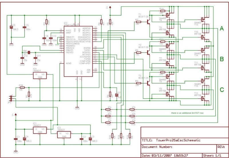
Really there shouldn't be a whole lot to making one of these, though the power supply might be problematic as it appears to be a dual polarity supply; easy enough with batteries, bit less easy with stock power supplies. For higher voltage, single supply operation H-Bridge drivers could allow the use of N-Channel FETs or IGBTs and a much less expensive power supply (albeit with the added expense of charge pumps//drivers).
I blew-up my DSO a while back (doing something stupid, lol), but I was planning on getting another one in the near future anyway, so this project may just push that timetable up! I have always been interested in 3-phase motor drivers, so I am planning on ordering a BLDC motor and start playing! Any of you RC people who want to recommend a particular make/model of BLDC motor, PLEASE speak up. I am thinking something in the 1kW range for starters; likely an "out-runner".
Fish
-
06-15-2011, 12:15 AM #39
Registered
- Join Date
- Oct 2006
- Posts
- 120
best bet would be for you to go into your local hobby store and ask for a 1000watt motor. they will probably ask "what for?" and take it from there.
i would say go for a high volt motor (less amps) normally called a 12s (44.4v or 50 odd volts with fully charged cells) motor. then pick you KV (rpm/v) will probably be around the 500kv. but as i've said before, that's still a shed loads of amps.
this is the specks for a 600/800watt motor.
●Input voltage C11.1V-22.2V 3-6cell Li-Po
●Max continuous current: 4S 45A/55A(30sec)
6S 35A/45A(30sec)
●Max output power:650W/800W(30sec)
●KV value:1600KV
●Dimension: spindle 5x36x61.1mm
●Weight: 200g (prox.)
specks for a 1800/2200watts
●Input voltageC11.1V-22.2V 3-6cell Li-Poly
●Max continuous current:80A/95A(60sec)
●Max output power:1800W/2200W(60sec)
●KV value:1220KV
●Dimension: spindle Φ6xΦ43.6x59mm
●Weight: 310g (prox.)
2000/3000
●Input voltageC11.1V-25.2V 3-6cell Li-Poly
●Max continuous current:90A/150A(5sec)
●Max output power:2000W/3000W(5sec)
●KV value:1220KV
●Dimension: spindle Φ6xΦ45x59mm
●Weight: 320g (prox.)
edit........ no i didn't put the little green faces in there.
-
06-15-2011, 12:53 AM #40
Registered
- Join Date
- Apr 2009
- Posts
- 165
Blighty,
I like the smileys...Anyway another good place to look for a motor is on some of the RC airplane and heli forums. I am a RC heli guy so I went to Home - RunRyder RC Helicopter and bought a outrunner designed for an align 600 sized heli. It is a 1220 kv motor that handles close to 2KW but my power supply can only supply a max 1KW. Its very close in specs to the second motor blighty posted. One thing very cool about the align motors is they are actually outrunners but unlike most the outside of the motor doesnt spin. It was important to me for cooling options. Anyway check out the for sale section you an find some really good deals!
Eric

 Reply With Quote
Similar Threads
-
BLDC motor
By fraspelle in forum CNC Machine Related ElectronicsReplies: 8Last Post: 03-31-2020, 07:09 AM -
NM-145 BLDC motor problem
By Turbo442 in forum NovakonReplies: 4Last Post: 01-03-2014, 01:58 PM -
X2 BLDC Motor
By whitehedr in forum Benchtop MachinesReplies: 4Last Post: 11-11-2013, 05:53 AM
