


[ame=http://www.youtube.com/watch?v=roX1TNX05Vo]‪003‬‏ - YouTube[/ame]
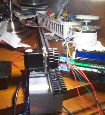
I have a black plastic rack and pinion that was designed for TV cabinet doors. The rack is attached to an aluminum rail that slides on a fixed Teflon type carriage. The rack and rail weight about 3 oz. together and offers little resistance. It is oriented vertically so I just goes straight up and down.
As you can see in the video, The motor isn't quite strong enough. I need to give the slide a little boost to get it started.
After I took the video, I added some code to give it acceleration but that wasn't enough to do the trick.
What can I do to make the motor have more torque? I don't know anything about electronics. Can I just up the voltage? I am using 12v now. ...or do I up the amps? I am using a 1.0A wall wart now. I also use 30V for the bigger first axis stepper motor. I also have a small box full of wall warts of various voltages but I might need to buy a higher amperage power supply.
This is the stepper motor:
Pololu - Stepper Motor: Bipolar, 200 Steps/Rev, 28x32mm, 3.8V, 670mA
This is the driver board:
Pololu - A4983 Stepper Motor Driver Carrier with Voltage Regulators
This is the code that I am using:
Code:void lowerTheBoom() { int j; int decelerate = 10000; digitalWrite(enablePin, LOW); // set the enablePin low so that we can now use our stepper driver. delayMicroseconds(2); // wait a few microseconds for the enable to take effect // (That isn't in the spec sheet I just added it for sanity.) for(j=0; j<=lowerTheBoomSteps; j++) { digitalWrite(stepPin, LOW); delayMicroseconds(2); digitalWrite(stepPin, HIGH); delayMicroseconds(decelerate); // was 1000 // Serial.println(decelerate); if(decelerate >1000) { decelerate = decelerate - 100; } //delay(100); } digitalWrite(enablePin, LOW); }
Thread: More Power for the Slide.
Results 1 to 13 of 13
-
07-27-2011, 04:46 AM #1
 Registered
- Join Date
- Apr 2011
- Posts
- 73
More Power for the Slide.
-
07-28-2011, 09:14 PM #2
Registered

- Join Date
- Feb 2010
- Posts
- 331
will it work in the horizontal position? if it does then the motor may not be strong enough to lift it. if it does not then it is probably something with your code.
try accelerating and decelerating it gradually. this is normally how steppers are used in cnc control. they gradually accelerate up to top speed, then gradually slow to a stop. asking it to go from 0 to 100, instantly is too much for any motor.
-
07-28-2011, 10:26 PM #3
Registered
- Join Date
- Apr 2011
- Posts
- 73
I just finish adding acceleration to the code and it didn't quite do the job.
-
07-29-2011, 01:40 AM #4
Gold Member
- Join Date
- Jan 2010
- Posts
- 2141
How are you setting the current to the motor (to equal the rated winding current)?
Does your wall-wart have a built-in current limiting regulator? Maybe the wall wart is preventing your driver from supplying adequate current to the motor.
Do you have a power supply with a higher current rating (for example, one that can supply 2 amps)?
What step size are you using? Can you set the step size from the microcontroller, or is the step size hard-wired?
If you are using microstepping now, have you tested it with full- or half-stepping to see whether it starts by itself in those modes?
-
07-29-2011, 07:41 PM #5
Registered
- Join Date
- Oct 2005
- Posts
- 2392
I remeber that rack from another thread...

That stepper motor is rated at 8.7 oz-in, which is VERY small amount of torque. Your pinion gear has a radius about 0.55 inch so even under *perfect conditions* with NO friction it will only make about 8.7 / 0.55 = 16 ounces of linear force.
Throw in a bit of friction or the weight of that long rack (if vertical) and that motor just won't move it.
Maybe you can add some gearing to the motor, or even get a much larger motor? Do you need that motor to lift the full weight of the rack slide and everything on it?? If so it's going to need some weight figures and some calculations...
-
07-30-2011, 04:31 AM #6
Registered
- Join Date
- Apr 2011
- Posts
- 73
Yes I have had to be helped through every phase of this project. This is my sixth thread including the last one that you helped me with:
http://www.cnczone.com/forums/hobby_...eed_brake.html
The 8.3 oz. is a good though! It does have enough power to lift the slide rack straight up hill with power to spare but not enough to get it started. I only plan to add a very small plastic clip to hold a ¼” or 3/8th tube. It just drops the tube into the larger tube/tower so that the water and food don’t spray all over the place, missing the tower opening. Thing of all the times you see the evidence of guys missing the toilet.
If the second axis works, I hope to add dividers between the towers so that popping air bubbles don’t splash plankton from one culture to the next, providing cross contamination. The second axis will get up and over them and help deliver the food and water below the rim of the towers.
I’m wondering if going to a 2A power supply would help?
-
07-31-2011, 11:08 AM #7
Registered
- Join Date
- Oct 2005
- Posts
- 2392
Ok, you said the motor will lift the weight of the rack and you seem committed to that motor. Personally I like a large torque surplus, as it might be heavier when wet, or something light get sticky later etc.
But if you want to keep with that motor you can overdrive the current, which will increase torque. The problem is greatly increased motor heating but if I understand you right this will only be used for a few minutes every few hours? In that case try upping motor current by about +60%, and try that. You can even try +100% for short periods of time (like a minute or so).
I assume you are using a microstepping mode on the driver, like 16th stepping? That is probably best, it has less holding torque than the full step mode but with your large pinion diameter the microstepping will give much less resonance when in motion which is probably more important.
Your acceleration code uses a linear change in period per step, which gives a poor acceleration curve. At the very least you can change to a percentage change in period per step that will allow much better acceleration. You could modify your code to be something like this;
What that does is subtract 1/1024th of the period every step, so at the start when period is 10000 it is subtracting about 10 each step, and near the end it is only subtracting about 1 each step. That gives you a much improved acceleration curve.Code:if(decelerate >= 1024) { decelerate = (decelerate - (decelerate/1024)); }
Good luck.
-
08-03-2011, 04:15 AM #8
Registered
- Join Date
- Apr 2011
- Posts
- 73
I hope to be able to stick with the small stepper motor. I don’t mind spending more money on a different power supply if needed but I want that motor because it is so light weight. If this one doesn’t do the job well enough, I might try a geared motor but I have a lot of time invested in it.
I added the acceleration code (thank you) and I tuned it a little. I also tuned the current limit pot on the controller board more closely.
With that, I got it to work. I haven't aligned all of the parts like the angles of the motor mount and the alignment of the slide guides but with that, it should work better.
It does appear to have the power but at the low end, it is still right at the edge, just barely starting. It does bind a little, on start up once in a while, usually the first time I run the program. I think that with more tuning of the code, I can get it to be smoother.
As you can see, there isn't much of a margin of error. I don't know if I should buy a power supply with 2A's or just use a wall wart with a higher voltage and then retune the limiting pot.
[ame=http://www.youtube.com/watch?v=dK4hXVRhH2k]‪000 1969‬‏ - YouTube[/ame]
-
08-03-2011, 07:28 PM #9
Registered
- Join Date
- Oct 2005
- Posts
- 2392
Well congrats! You've got it most of the way.
I would still be a little wary of being so close to the limit. It's nice to have a decent safety margin, so your machine is reliable.
You said you tuned the current limit pot, what current are you running the motor on now?
-
08-03-2011, 08:16 PM #10
Registered
- Join Date
- Apr 2011
- Posts
- 73
I will need to put a meter on it. Up until now I just turned it until it started to malfunction and them back it off just a little.
THe guy that sell it said that once it is set, you don't have to re-tune it if you change the V or the A but I should measure it now AND if I change it.
-
08-06-2011, 04:08 AM #11
Registered
- Join Date
- Apr 2011
- Posts
- 73
I wrote and asked for help and got some but as I've said, I'm not an electronics guy. I just didn't understand how I was suppose to measure current of voltage. While the explanations would be clear to someone else, I am embarrassed to ask over and over again. The explanations have all been over my head. This is the best so far.
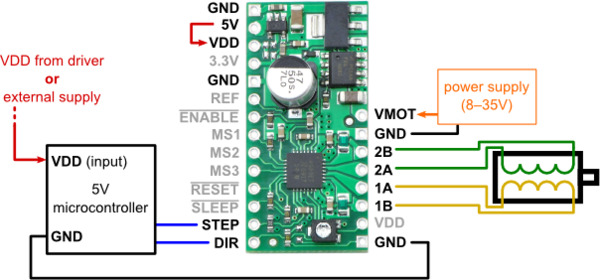
Can you tell me what wire goes where or what do I measure? This is the way that I wired the motor.I suggest you disconnect your Arduino from the stepper motor driver (which wire?) and measure the current flowing through one of your stepper motor coils while the STEP and DIR pins are connected directly ground( both connected to a ground pin?). Your current limit will equal this measured current divided by 0.7, and you can adjust it to your desired limit by turning the pot.
Alternatively, you can measure the Vref voltage directly on the driver pin labeled REF. A voltage of approximately 270 mV on this pin corresponds to a current limit (per coil) of 670 mA. (I touch the REF pin but I touched GND but I got nothing). This is probably the easiest way to set the driver's current limit as you don't even need to have a stepper motor connected. All you need is to power the board and hold the STEP and DIR pins fixed low or high.
-
08-06-2011, 05:02 AM #12
Gold Member
- Join Date
- Jan 2010
- Posts
- 2141
I don't think that you can easily measure the actual current through a motor winding, because the driver "chops" the voltage going to the winding.
So, instead, it should be easy to measure the voltage at the pin labeled "REF", and then calculate the maximum current setting of the driver based on that voltage. The driver will send that much current through each motor winding as long as your power supply is capable of supplying that much current. The driver is rated to handle up to 2 amperes of current per winding (if I have read the specs correctly).
First, you need to be set up to measure the voltage at the REF pin. Then you need to do a quick calculation to convert that voltage reading into the corresponding current limit.
After you've figured out the current limit setting, if you then want to change the current limit setting, you can use a small screwdriver to turn the potentiometer (which I believe is on your driver board) to a different value, and then go back and repeat the voltage measurement and current calculation.
Following the instructions that you quoted, first disconnect the arduino from the driver board, then connect the DIR and STEP pins of the driver board to GND (you can use alligator clip leads for that if you have them, just be careful not to short out any other pins or parts of the board).
Then, take a digital multimeter, set it to read DC volts with a maximum range of 1.0 volts or 2.0 volts or whatever low range you have. Connect the black lead of the multimeter to GND. Connect the red lead of the multimeter to the REF terminal of the board. If your multimeter has a separate on/off switch, turn it on.
Then apply the 5 volt power to the driver board (for this measurement, I don't think that it matters whether or not the motor power supply is also turned on).
You should be able to read a voltage from the voltmeter. It may be a decimal fraction that is less than 1 volt. Write down that value.
To calculate the maximum current setting from that voltage, you need to use the formula given on page 7 of the Allegro A4983 datasheet at http://www.allegromicro.com/en/Produ.../4983/4983.pdf
That formula is: Current = Voltage divided by (8 times the value of the current sensing resistor)
Based on the schematic for the Pololu driver board (shown at the bottom of Pololu - A4983 Stepper Motor Driver Carrier with Voltage Regulators), it looks like the value of the current sensing resistor (labeled either R10 or R11 in the schematic) is 0.05 ohms.
8 x 0.05 = 0.4
So, to get the maximum current setting, divide the voltage that you measured above by 0.4.
For example (as given in the instructions that you quoted), if you measured the voltage at the REF terminal as 0.270 volts (which is another way to say "270 mv" or "270 millivolts"), then you need to divide 0.270 by 0.4, which gives you 0.675 amperes as the maximum current limit. 0.675 amperes is equivalent to 675 milliamperes, which is close to the nominal maximum current rating of your motor winding.
If you adjust the on-board potentiometer to a different value, measure the resultant voltage on the REF terminal, and recalculate to get the new maximum current limit.
Hope that makes sense.
-
08-06-2011, 06:25 AM #13
Registered
- Join Date
- Apr 2011
- Posts
- 73
Thanks it made some since.
As a side note: I was getting .4 ohms when I measured across two wires of one coil.
I don’t know if I was doing it right but I turned the voltage setting on the meter to 2.5 and got 20 on the top DCV line. It I turned it up to 10, I go nothing.
I was giving it 12V for the above readings. I didn’t have 5V so I also used 6V and I got the same reading.

 Reply With Quote
Similar Threads
-
Compund slide table and NEMA 23 stepper enough power?
By Apples in forum Linear and Rotary MotionReplies: 6Last Post: 11-01-2010, 08:49 PM -
z slide
By JackBlack in forum Want To Buy...Need help!Replies: 0Last Post: 01-30-2009, 01:51 AM -
Home made cross slide power feed for small lathe
By monte55 in forum Uncategorised MetalWorking MachinesReplies: 3Last Post: 12-16-2007, 08:30 PM -
SX3 -- Can't get the bed to slide off~~
By krazatchu in forum Syil ProductsReplies: 5Last Post: 11-20-2007, 01:29 AM -
THK slide bearing
By Bill Davis in forum Mechanical Calculations/Engineering DesignReplies: 2Last Post: 08-27-2006, 12:31 AM
