


While I am finishing my archtop, I have started on an F5 mandolin.
I want to do the scroll and also get the surface thickness correct.
Despite a lot of comments on BobCAD, I find it good enough for me to do what I want (to date).
Occassional problems such as falling over, but just remember to save often.
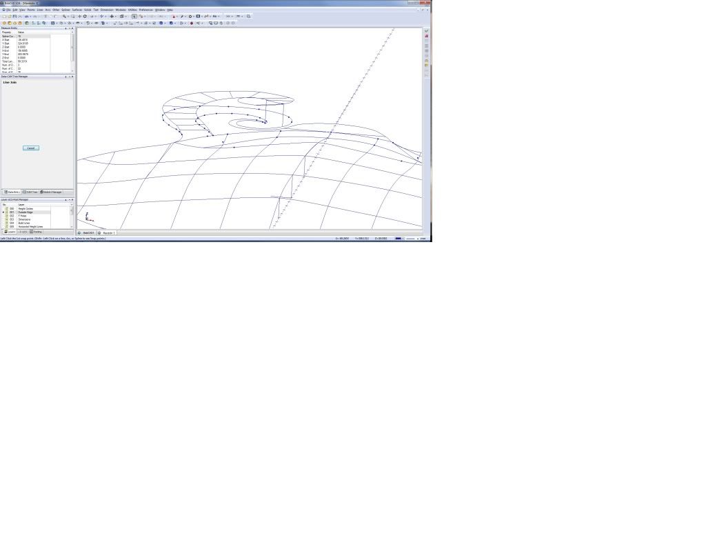
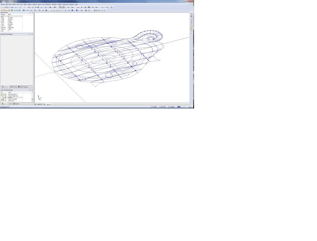
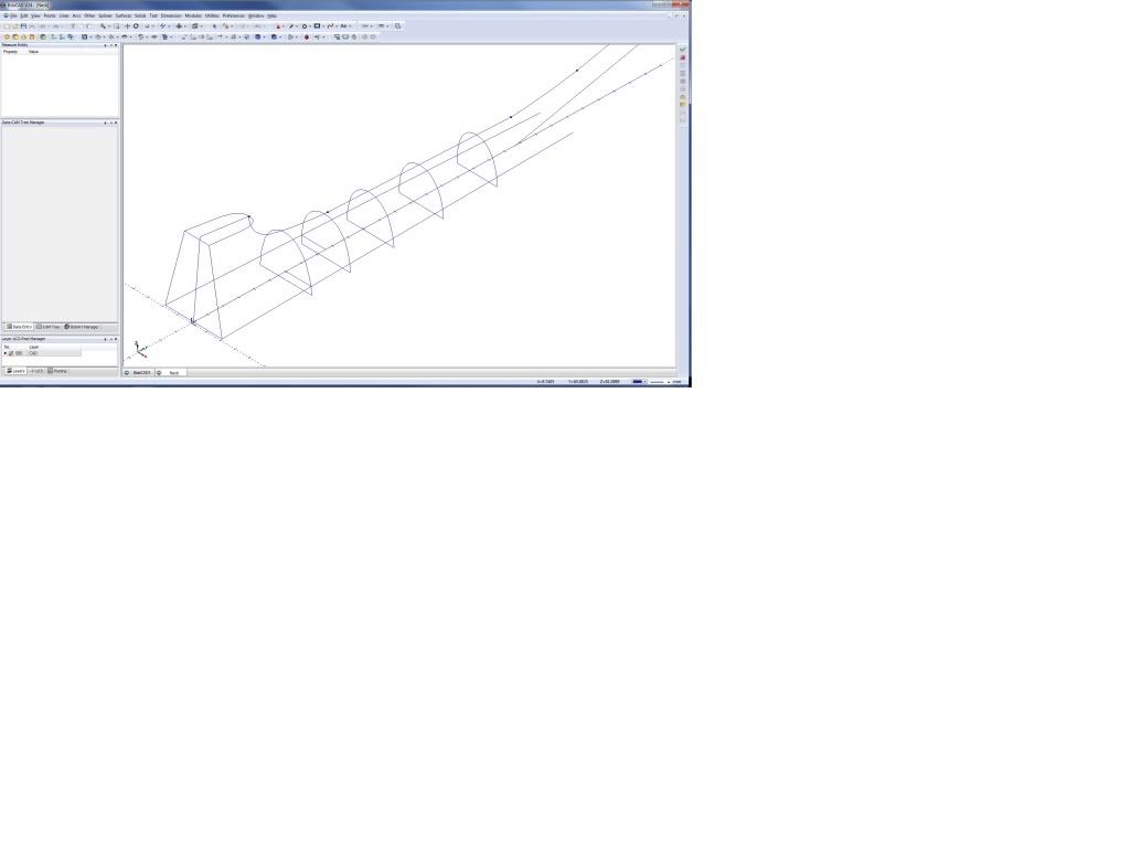
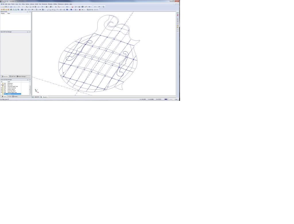
Wire frame:
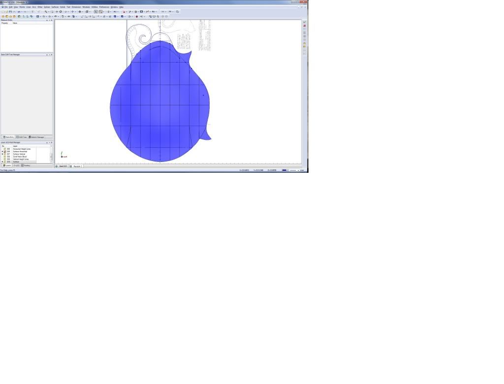
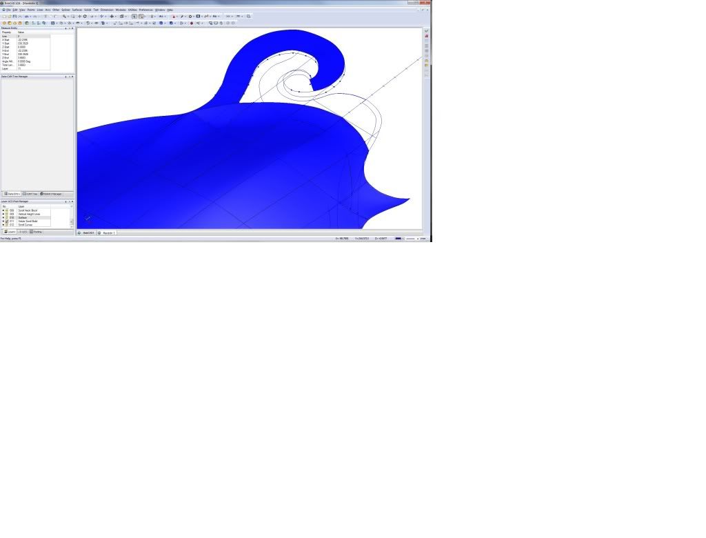
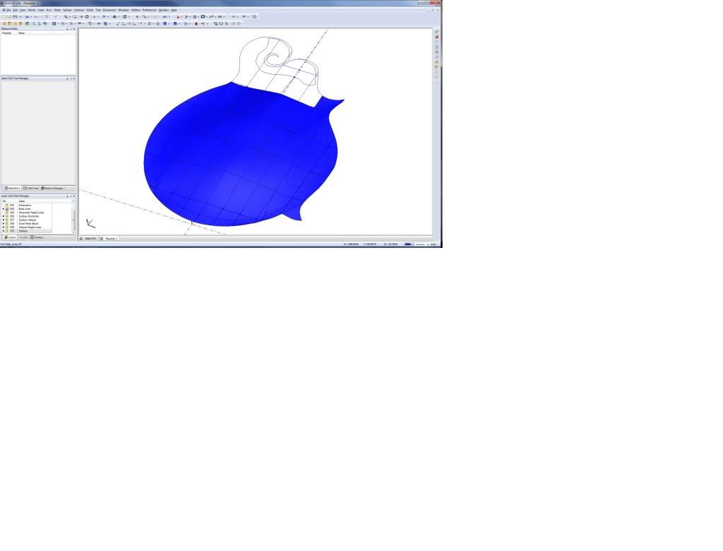
Surface to date:
Still need to work out what happens at the neck and scroll, and also what happens at the triangular bits (are they curved, flat etc).
Garry
Results 1 to 20 of 65
-
08-28-2011, 01:22 PM #1
 Registered
- Join Date
- Apr 2011
- Posts
- 0
My Mandolin Surface Post in BobCAD V24
-
08-29-2011, 06:16 AM #2
Ghost
- Join Date
- Dec 2008
- Posts
- 4548
Hi Gary, should be an awsome watch... Rememeber that if you go to view menu and turn on "Wireframe", this will show the Isoparams of the surfaces.. This can help you check for any "kinks" in the surface that may not be apparent.. Just in case you didnt know... Nice work.
-
08-29-2011, 11:05 AM #3
Registered
- Join Date
- Apr 2011
- Posts
- 0
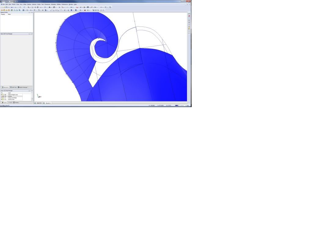
More Top Surface
Bit more done. The book I am using is a bit sketchy on how the curve transitions at the neck. After looking at the book's pics, I think it looks like this:
Now onto the scroll.
Garry
-
08-29-2011, 12:07 PM #4
Registered
- Join Date
- Apr 2011
- Posts
- 0
Volute Scroll Started
Actually pretty easy:
Top is 12mm higher than bottom in this drawing. It should be 4mm after reading the book to work it out. Length of curve was 99mm. Stepped down 1mm starting at 12mm every 8.25mm along the curve, then projected to the other curve using point perpendicular.
Then Joined everything up:
Update
Redid it at 4mm height difference:
-
08-30-2011, 09:09 AM #5
Registered
- Join Date
- Apr 2011
- Posts
- 0
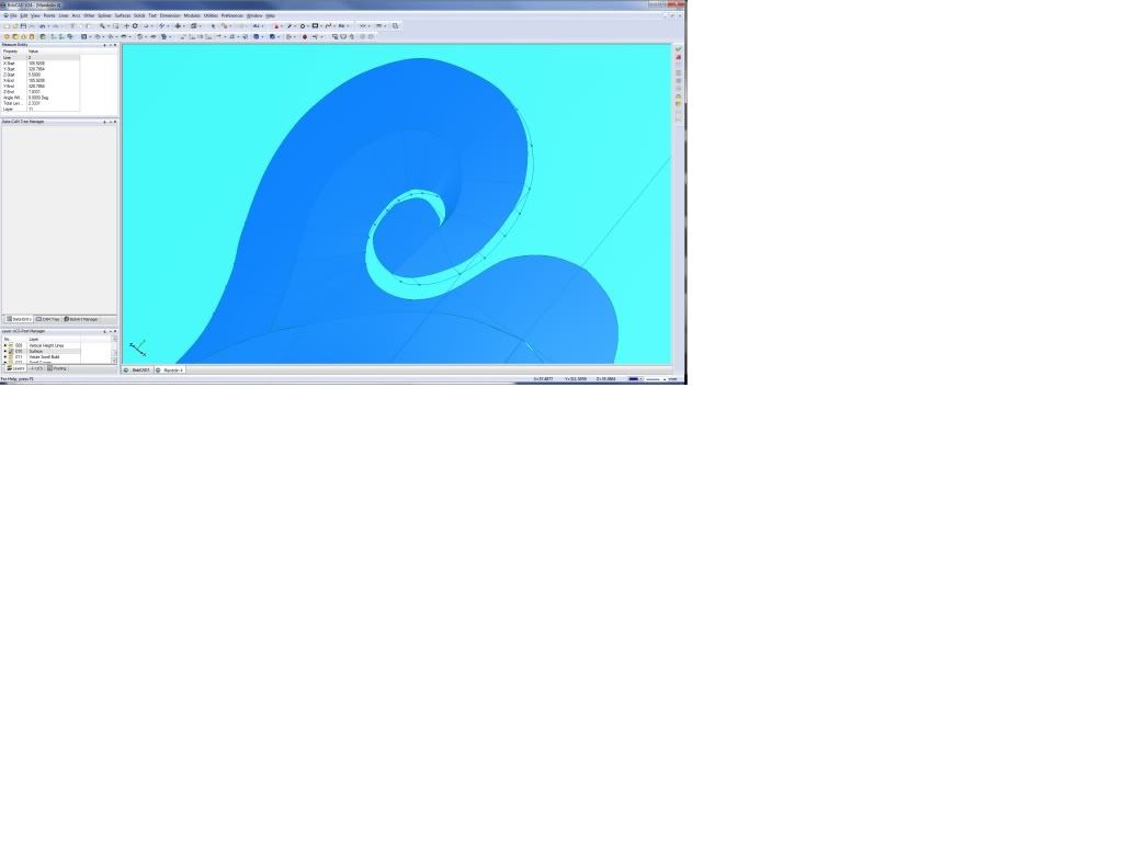
First Go at the Scroll Bevel
I will probably run with this as I can manually adjust:
Garry
-
08-31-2011, 10:20 AM #6
Registered
- Join Date
- Apr 2011
- Posts
- 0
Redid the Scroll/Volute
Looked at some F5 mandolins and pics and also found an error in my curve heights.
Redid the design with a 0.6666 difference from the 'middle' line of the scroll to inside and outside curve perpendiculars:
Backplot in fine profiling:

Ordered the wood to make it all from Stew-Mac.
Hope to get the binding on my hollowbody this weekend.
Garry
-
08-31-2011, 12:50 PM #7
Registered
- Join Date
- Apr 2011
- Posts
- 0
F Hole Pocket
Did the toolpath and code for the F Hole pockets and did a backplot in Predator CNC Editor V7:

I will a test mill on some ply next. The thickness of ply and top/bottom plates are both 19mm (or the plate stocks will be 19mm when I thickness them), so makes it easy.
The vertical line is the representation of the milling tool, not a bad or spurious cut...
Garry
-
09-01-2011, 09:32 AM #8
Registered
- Join Date
- Apr 2011
- Posts
- 0
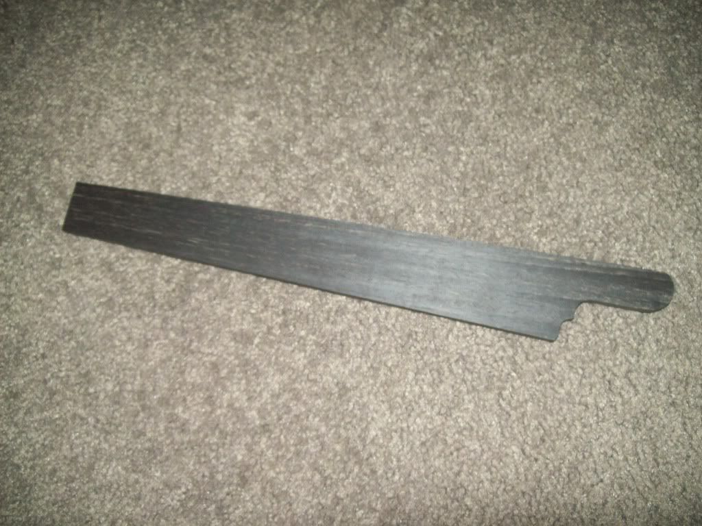
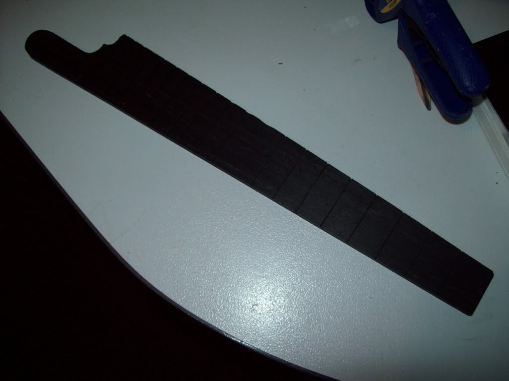
Fretboard
I did a test of the fretboard. Thicknessedd to 5.5mm and left 0.5mm around the profile:
-
09-01-2011, 02:28 PM #9
Company Representative

- Join Date
- Jun 2003
- Posts
- 446
Aussiegazza I've been tracking you up here and it looks like you are doing some really nice work with our software. Do you use BobART for anything?
CNCdude
-
09-02-2011, 05:54 AM #10
Registered
- Join Date
- Apr 2011
- Posts
- 0
I have been using BobArt to scan in the shapes and templates. That's as far as I have gotten with it. Very useful! Having a scanned image in the background SHOULD be a standard feature of BobCAD. Rest of it I do not require at the moment. Originally Posted by CNCdude

I do not use the raster to vector options as I have not really had time to learn (tried once), and also because I want long vectors/curves. Not a lot of short ones.
Also my scanner is accurate in the Y direction, but not so accurate in the X direction. I therefore put size lines or points onto the scanned images and correct for the inaccuracy as I trace the shape with the interpolated curve option. Therefore another reason not to use BobArt, as I need to adjust the shape anyway.
In woodworking, a slight error can be allowed. I am more worried about
symmetry. I therefore draw half the shape and use mirror to complete it. Again, why I do not need raster to vector.
BTW to others who may read this, I DO NOT have any relationship with BobCAD, other than I bought their product like everyone else. I could have used Mastercam 4 that has been pirated, but I wanted a legal, supported software product. My son has Solidworks on his laptop, but it is too expensive. I can get him to do things if I need to, but so far, no need.
Update:
I can fit a mandolin neck onto my 'small' mill, so I want to mill the neck:
You can see my use of BobArt in the head profiles below. I will mill the head so I can easily get most of the tight curves at the 'volutes':
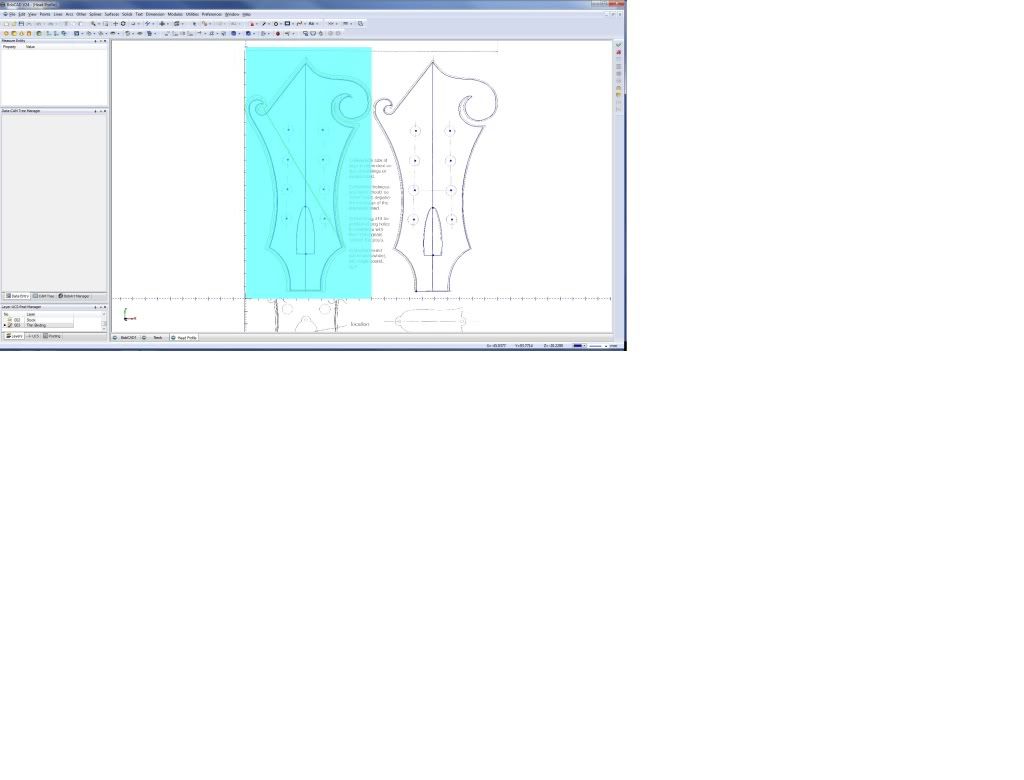
Garry
-
09-02-2011, 09:14 AM #11
Registered
- Join Date
- Apr 2011
- Posts
- 0
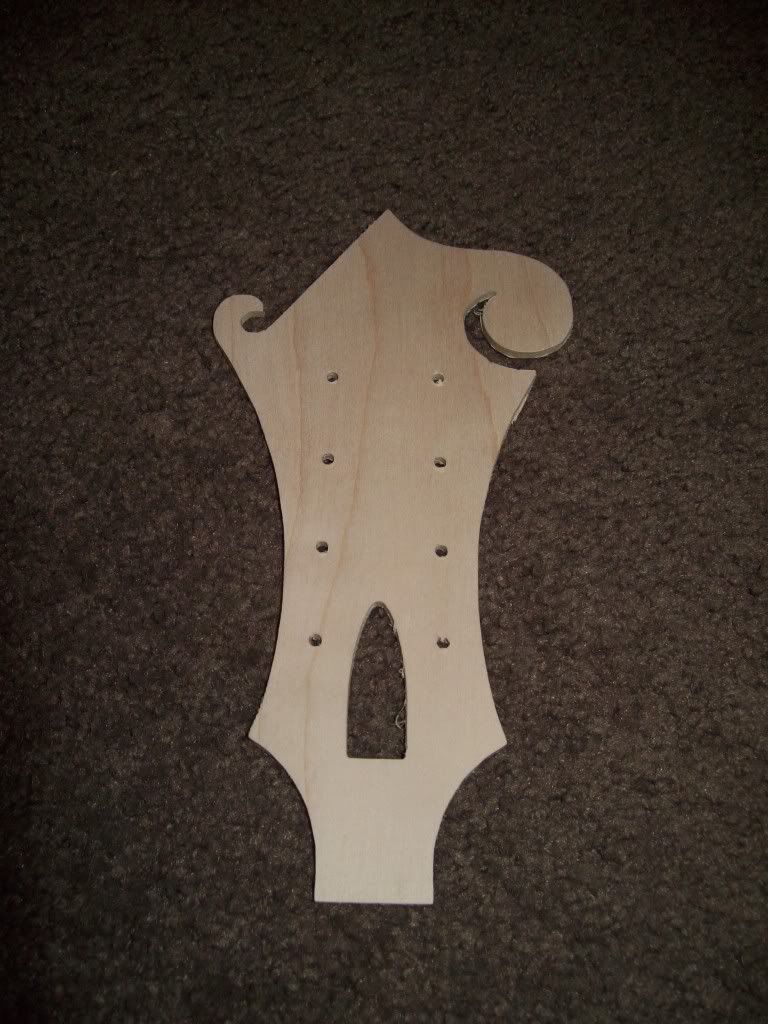
Head Plate Test
Test Mill of the head plate. Even used a drill profile for the first time!
-
09-02-2011, 12:59 PM #12
Registered
- Join Date
- Apr 2011
- Posts
- 0
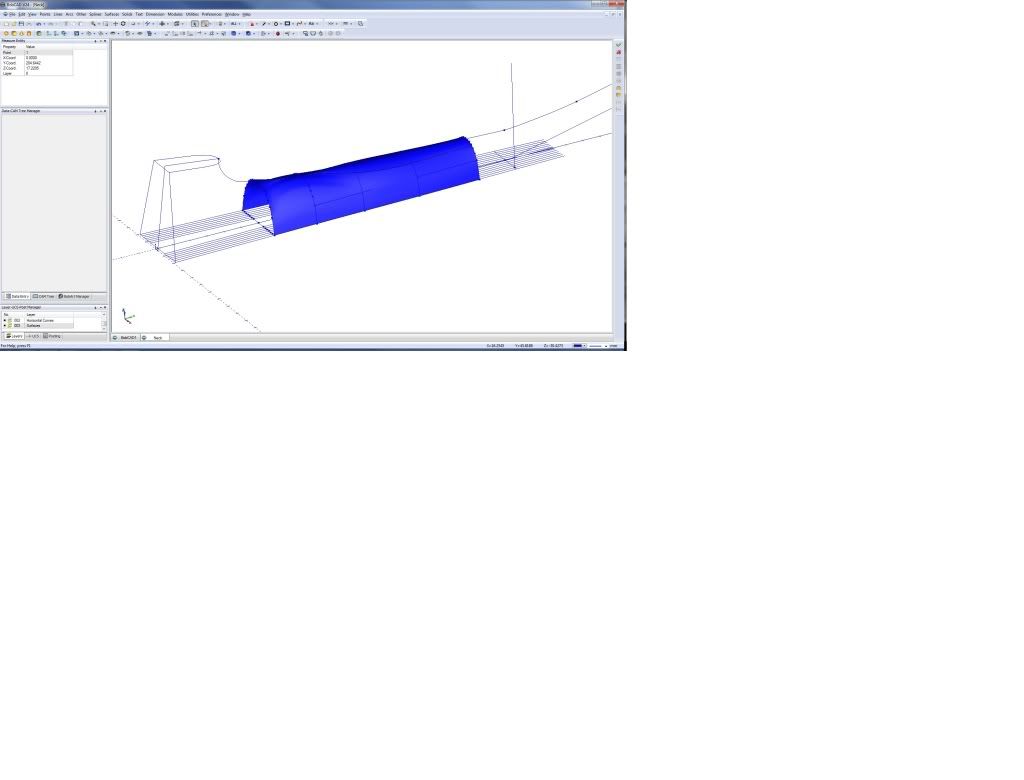
Neck Surface Extrapolation
The book I am using only has 5 neck profiles, so I need to extrapolate both ends of the neck.
Here is my approach:
Drew the 'wire' curves of the known profiles and then did a 'Cross Section' surface (actually did some more but the 2nd pic shows the surface):

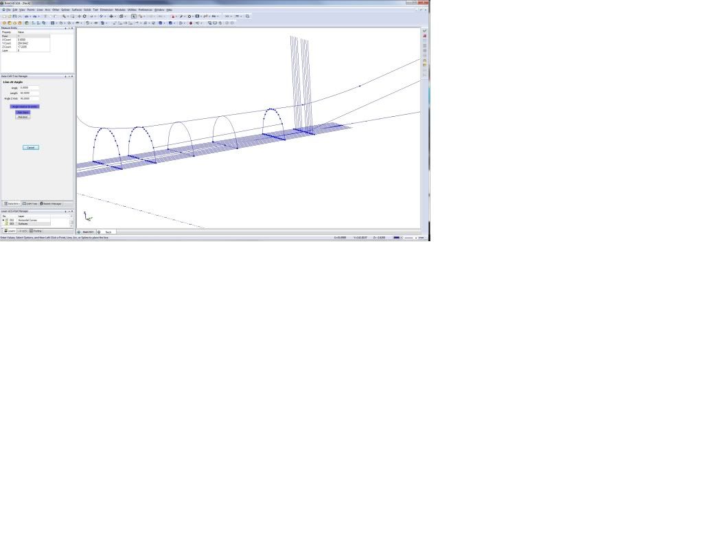
Then did lines parallel to the fretboard surface edges and put points at the intersections. Drew vertical lines from these points and put more points on the surface curves where the vertical lines intersected:
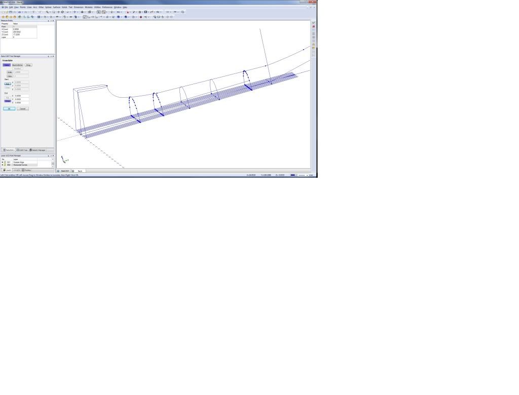
Put points on the parallel lines at the location I want the new curve and drew vertical lines from them:
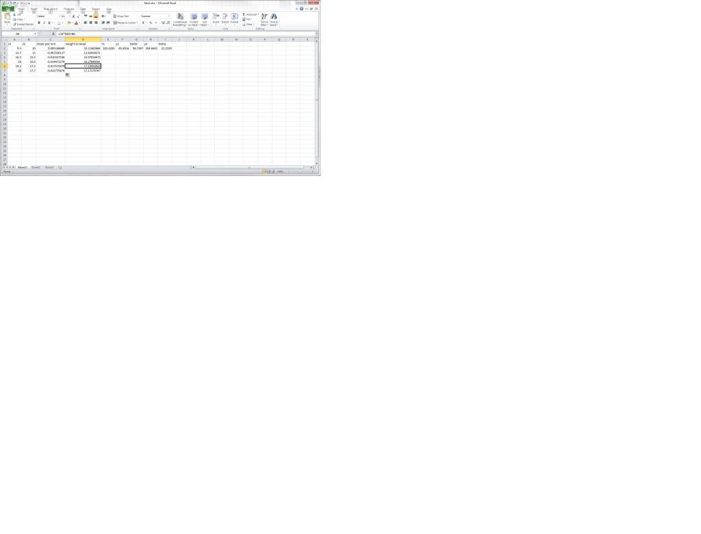
Here's the tricky bit. I calculated the slope of the lines through the points on the existing curves. When divided by the distance between the curves, you get the 'slope'. I did it in Excel and this results in a 'drop/slope per millimetre'. I know the distance to the new curve, so I can extrapolate the heights of the respective lines based on the curve heights at the last curve I know about:
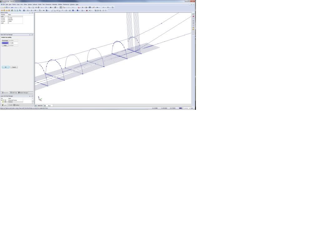
Put points on the lines and I have a new curve:
Then did another surface:
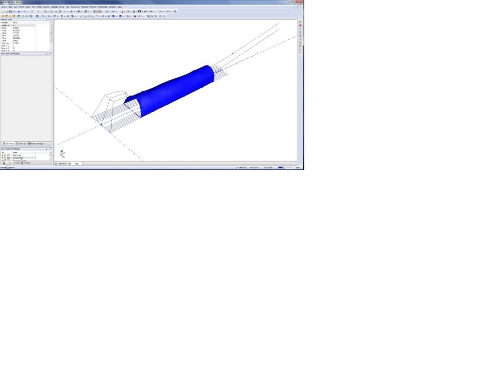
I hope you can understand all this ;-)
Now need to do this at the heel end and blend in the actual heel as well.
Garry
-
09-03-2011, 08:50 AM #13
Registered
- Join Date
- Apr 2011
- Posts
- 0
Neck Template
I scanned the template and used BobArt so I could trace it.
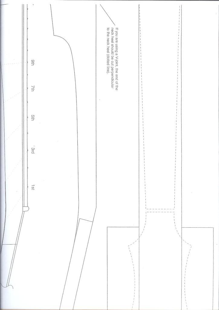
Here is the backplot:

I will use two 1 inch sides of birds eye maple with black veneer in between to add some contrast (ie a line up the middle of the neck). Neck is normally made from 2 inch stock.
Garry
-
09-04-2011, 02:21 AM #14
Registered
- Join Date
- Apr 2011
- Posts
- 0
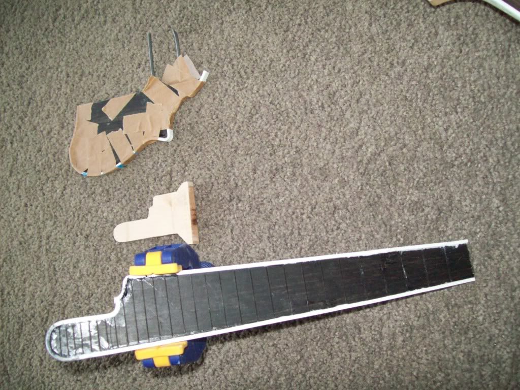
Templates and Neck Profile Done
My archtop is drying, touching up binding joints (you use plastic binding melted into acetone) etc, so moved more onto the Mandolin.
I machined the neck template and cut the 2 neck pieces out on a bandsaw. Currently drying after I glued them together with black maple veneer in between.
Templates:
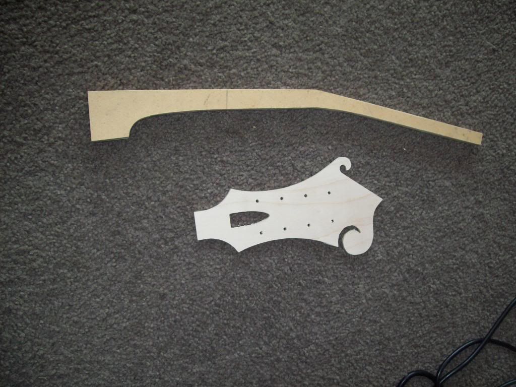
The head plate is machined 1.5mm undersize to allow for the binding. I was thinking of using it as the template for the binding when glued onto the head. Not sure yet. Need to ensure I cut the actual head OVERSIZE 1.5mm though.
Also nearly finished the neck surface:
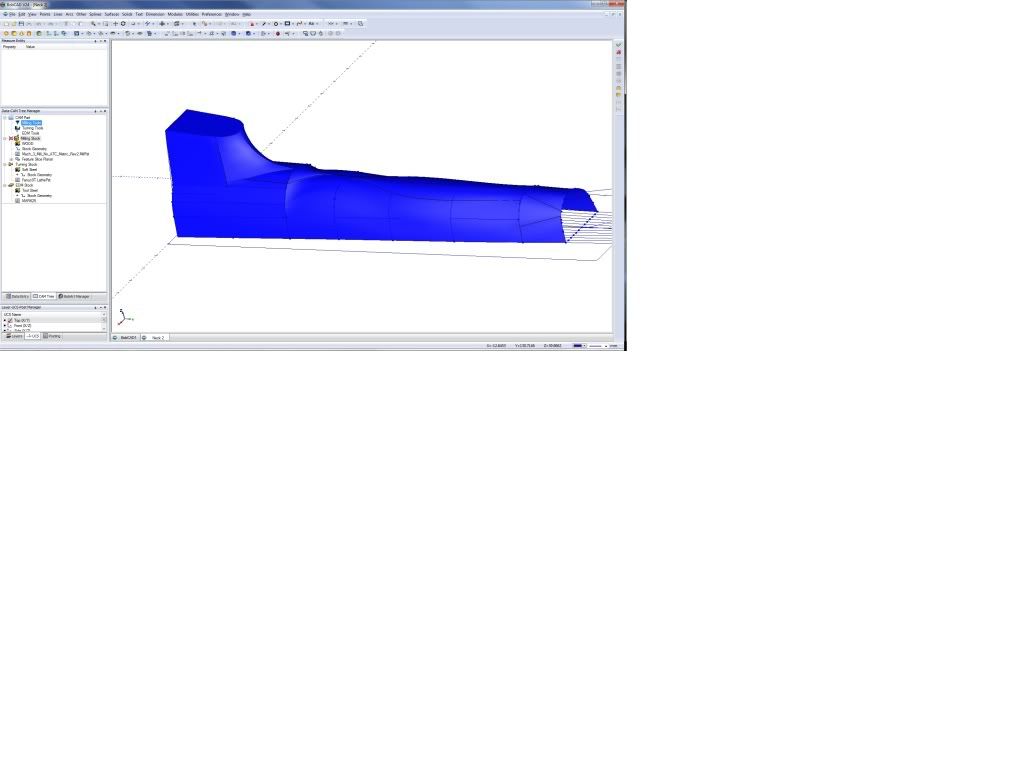
Some of the transitions are not totally correct, but I will finish them manually after machining. I made sure they are oversize to allow for this.
Garry
-
09-04-2011, 07:04 AM #15
Registered
- Join Date
- Apr 2011
- Posts
- 0
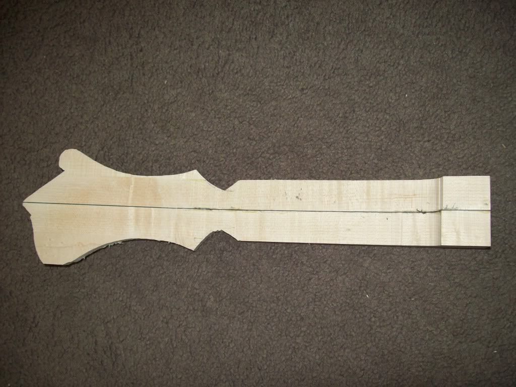
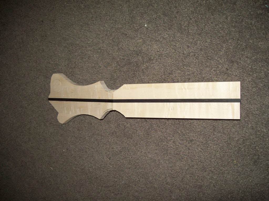
Neck and Head Roughed In
Made up a neck and head as discussed. The topside is in the first picture. If you look closely at the scroll at the top left of the pic, you will see the stengthening plug that goes halfway through. Used a forstner bit and a plug cutting bit. The plug has grain at 90 degrees to neck:
Did a mill and found two mistakes:
1. I did not put a sloping surface at the heel and ended up with part of the neck's dovetail area cut vertically down to the next surface, and
2. made the boundary the fretboard edge and the mill therefore did not go all the way to the bottom of the wood:
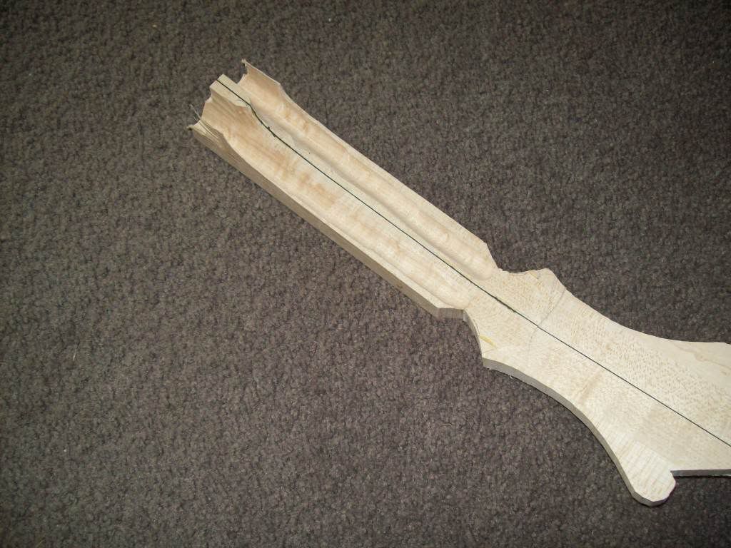
I can fix the heel as long as the patch is in the dovetail. This may weaken the joint. If I am not sure, I will make another neck. I will manually finish this particular neck.
Garry
-
09-05-2011, 09:16 AM #16
Registered
- Join Date
- Apr 2011
- Posts
- 0
Stuffed Up Milling...
I changed the design and decided that I would test it on this neck as I had, already, more or less stuffed it.
Lucky I did, as the rough cut worked perfectly, but the finer finishing cut caused the Z axis screw to hit the head as it moved in the Y direction.
This caused the neck to kick up (I was using double sided tape) and stuff up the neck.
I decided I wanted to continue so I could see where the screw is just about to touch in the Y direction. I therefore held the heel as it kicked up, pushed it back down when I could, and I got one side done correctly.
Design is very nice, I really just need a longer 2mm router bit for the fine finish, or stop 30mm short of the head.
I also want to leave wood at the heel for the dovetail.
Anyway, no great loss as the neck/head was actually very quick to make.
Pic of good side:
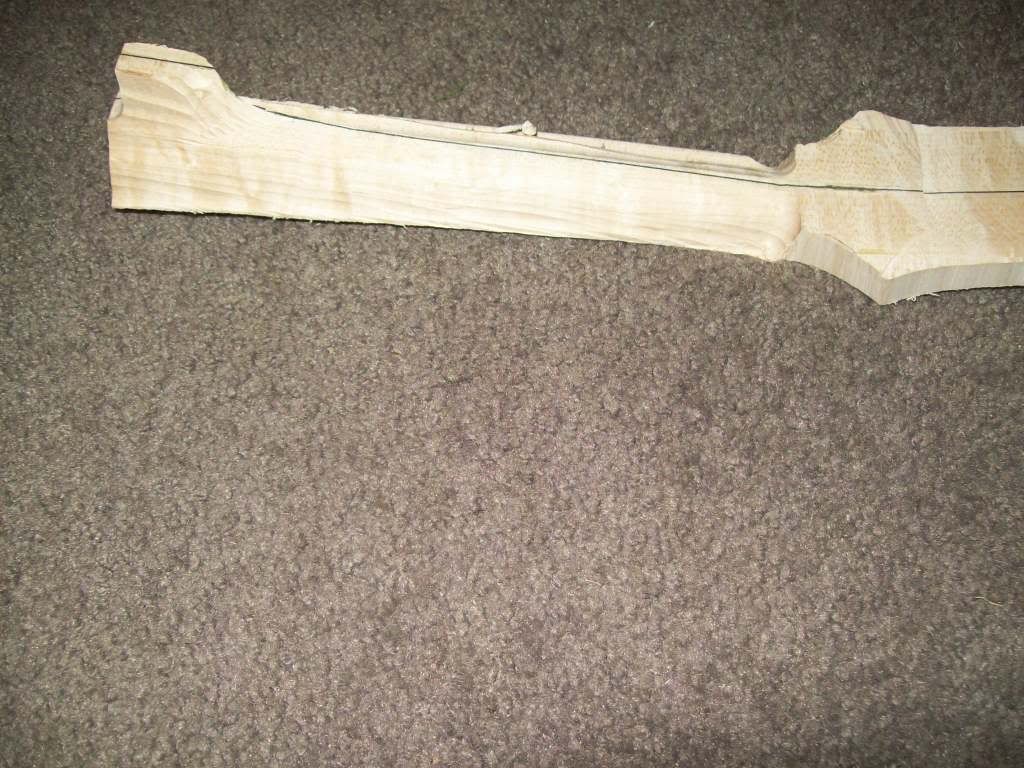
Bad side:
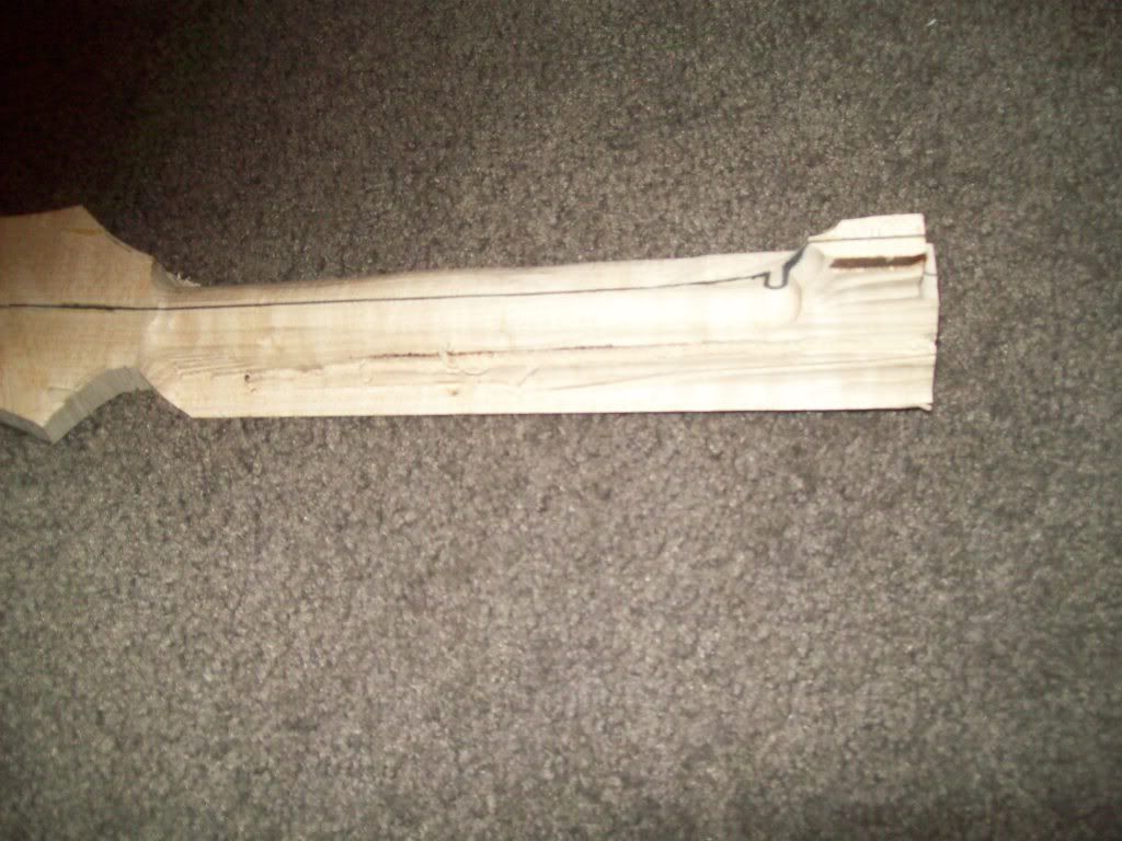
Back to scraping the hollowbody binding...
Garry
-
09-06-2011, 11:37 AM #17
Registered
- Join Date
- Apr 2011
- Posts
- 0
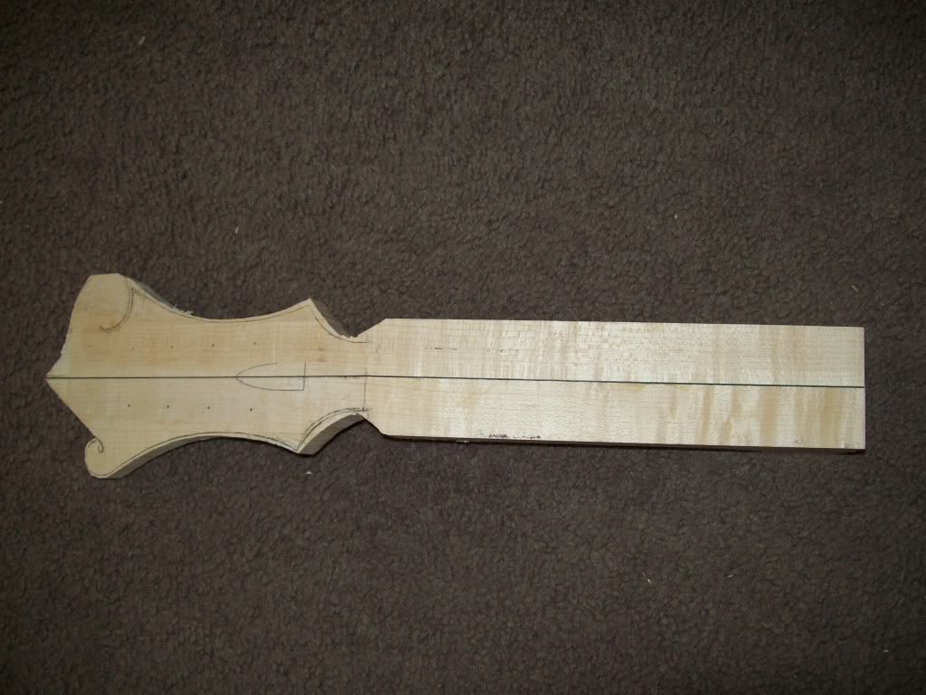
New Neck
Made a new neck with an ebony stripe up the middle:
-
09-07-2011, 09:55 AM #18
Registered
- Join Date
- Apr 2011
- Posts
- 0
Cut the Neck Dovetail
Read the manual and did the dovetail by hand and bandsaw.
You cut the head block to allow the sides to be set into it, then glue a block on top of it to allow the neck to extend over the dovetail. Then you bandsaw the block and top piece to make the dovetail:
Also made a jig to hold the neck at the correct angle on the bandsaw:
I know know where to stop the surface profile when milling so that the dovetail is not touched.
Update; Roughed in the dovetail into the head block. Need to manual finish:
Garry
-
09-09-2011, 09:00 AM #19
Registered
- Join Date
- Apr 2011
- Posts
- 0
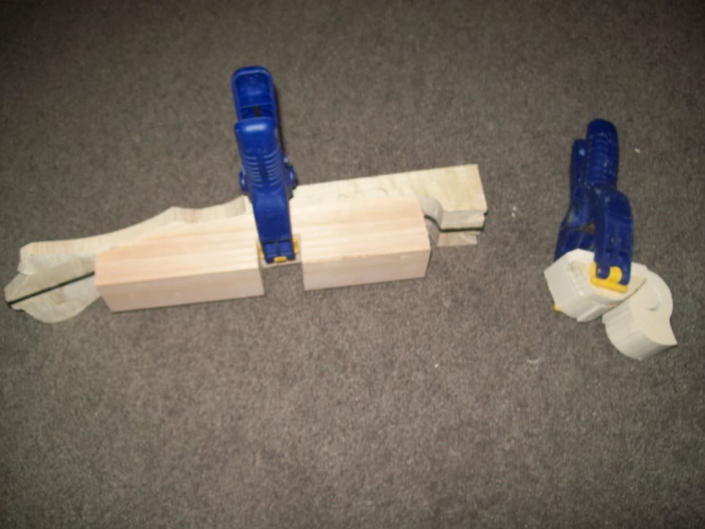
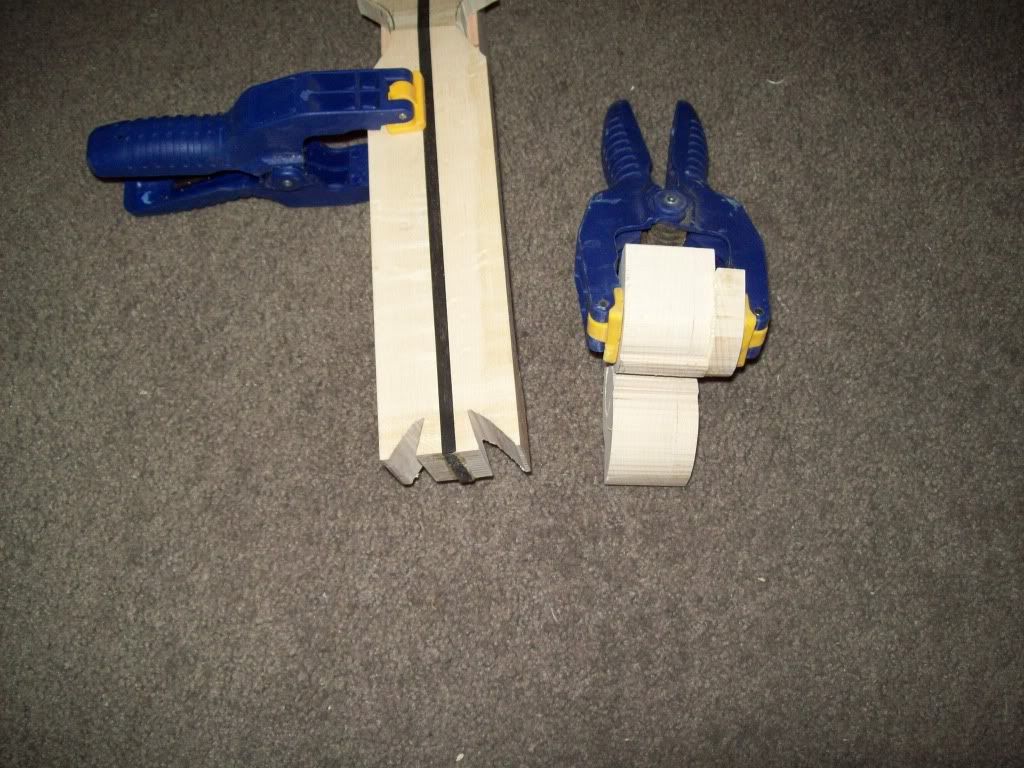
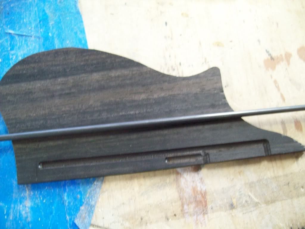
Finger Guard
Made the finger guard by cutting out on bandsaw.
Then used the mill with a beading bit, in jogger mode to inset the piano wire and I have it glued and clamped.
There is a strip (not shown) that is also routed at half the wire diameter that glues over the top to hold it all together.
Still need to put binding on:
Also cut the fret slots with a StewMac mitre box and template:
-
09-10-2011, 07:46 AM #20
Registered
- Join Date
- Apr 2011
- Posts
- 0
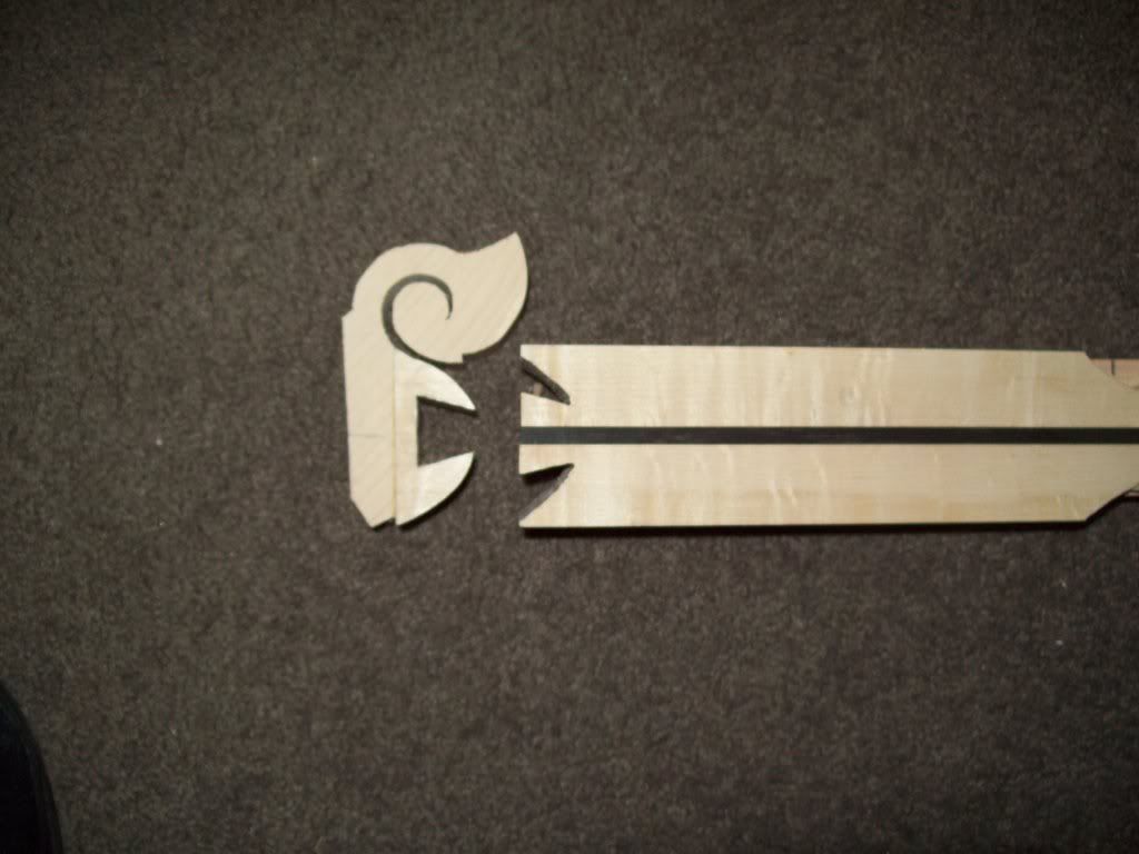
Accessory Binding
Did the binding on the fretboard and pickguard(nearly). Then went on to scraping and sanding my archtop:

 Reply With Quote
Similar Threads
-
Looking for Mandolin g code or dxf
By mredican in forum Musical Instrument Design and ConstructionReplies: 77Last Post: 01-12-2018, 12:02 AM -
Bobcad v24 Surface to Solid
By CADmantoo in forum BobCad-CamReplies: 5Last Post: 06-17-2011, 03:33 PM -
F5 mandolin
By bahed in forum Musical Instrument Design and ConstructionReplies: 0Last Post: 12-25-2010, 12:22 AM -
mandolin info:
By guitarman818 in forum Musical Instrument Design and ConstructionReplies: 1Last Post: 10-18-2006, 03:01 AM
