


Yes, I agree, that is a simple way of doing that. But I was actually trying to get a plot of the position error measured for various load conditions and directions. Obviously I could do that by hanging different weights (maybe I can take them off my workout machine) but the fish scale might be just easier.Originally Posted by RomanLini

Results 181 to 200 of 645
-
02-10-2012, 03:13 AM #181
 Registered
- Join Date
- Aug 2011
- Posts
- 999
-
02-13-2012, 01:00 AM #182
Registered
- Join Date
- Aug 2011
- Posts
- 999
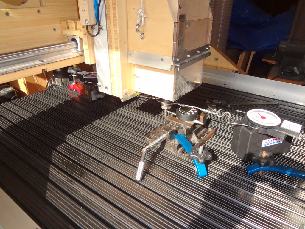
The rigidity measurement is in.....
So I rigged up my machine with the new precision indicator and 2 analog fishing scales (at $5.60 each I could afford it...). Both scales are mounted a bit pre-loaded to have a smooth transition through the zero-load point.
The result is quite interesting: While my machine frame and the gantry are rock solid (10,000 and 20,000 lbs/in for x and y respectively), the rigidity at the tool tip is much less (see numbers in the graphs). I guess this is probably a result of the open linear bearings blocks (I have 20mm Glacern supported rails) flexing a little for the Y and Z axis. I did already space them at a generous 12x12" for Y and 10x10" for Z. Probably not much more I can do there, other than getting better rails like HiWins.
Other insight:
- the tiny backlash of my Kuroda ballscrews is completely irrelevant, compared with the flexing error of the machine. Actually, I can not even measure it repeatably with the precision indicator.
- my simple hose clamp/cradle mount for the spindle is perfectly good. It does not change the rigidity with any significance.
I guess while not amazing, this performance is quite decent and will surely do the job for me. I would be really interested how other machines compare when measured that way.
P.S.: Sorry about all that data crap. But I am engineer by trade an can not live without


-
02-13-2012, 05:15 AM #183
Registered
- Join Date
- Jan 2008
- Posts
- 853
As a matter of principle, we should never apologize for precision, or for providing more, rather than less, information! This is the good stuff! And since the measurements are so easy to do and tell so much, we should all be doing it as a matter of habit. Originally Posted by JerryBurks
Is there anyway for you to measure the deflection of the tool with respect to the Z-plate (or spindle mount) to see how much flex the spindle itself is responsible for?
PS : I am trying to understand the need for the second opposing scale. Am I correct in thinking that the net applied force is the difference between the two readings?
-
02-13-2012, 05:34 AM #184
Registered
- Join Date
- Aug 2011
- Posts
- 999
Well, I was not planning to use 2 scales. I bought one at Wal Mart last weekend, put it somewhere in my chaos garage and then could not find it anymore. I cursed a bit but went out to Wal Mart again today and bought another one. That cost me probably more in gas than the scale itself. Originally Posted by PaulRowntree
Anyway as soon as I came home and unpacked the scale I found the first one. Cursed a bit more but finally was happy to use two because that allows me to scan through the push/pull load range without moving the scale to the other side. So it goes.....but you are right it is convenient but not strictly needed.
As for the tool deflection, that is actually the measurement #4. I did not use a real router bit but a 1/2" steel rod in the collet. As you can see there is no significant difference to the measurement from the Z-plate (#3). I did the latter with the indicator feeling a steel bar clamped to the Z-plate while the scales were still hooked to the collet (similar with the Y-plate and gantry measurements). That means the spindle and spindle holder do not contribute much if any to the flex.
Forgot to mention....To pull the scales I used the machine itself for simplicity, that means the other end of the scale is fixed. The position error is then the difference between the indicator reading and the CNC controller coordinate display. Alternatively you could leave the machine fixed and use a screw or or hoist or something to pull the scale. Then the indicator would read the position error (i.e. displacement) directly which might be a little more accurate.
-
02-13-2012, 06:12 AM #185
Registered
- Join Date
- Apr 2004
- Posts
- 141
Are your pillow blocks adjustable? Mine have setscrews to adjust the bearing preload. Loose, I can feel the motion in the bearings, but can tighten them up to balance rigidity vs friction (if too tight). Either way, this test certainly shows that your weak link are those supported round bearings.
-
02-13-2012, 05:33 PM #186
Registered
- Join Date
- Aug 2011
- Posts
- 999
Yes and no... Originally Posted by JohnZ
The fist set of linear bearings I got from Glacern and used for X and Y has the set screws you mention and I tried to adjust them as good as possible (it has very little range between loose and binding). The second set I bought for the Z-axis a few weeks later does not have such set screws for some reason, but the bearings felt nice and tight so I used them anyway.
But I have the impression anyway it is not so much play/backlash in the bearings but maybe the open cage is flexing a bit? Really hard to find out without measuring the bearing behavior individually.
I think I will leave it at that. The machine performance is more than adequate and I rather want to spend the time machining parts.
Next step is building a rotary axis (already got a nice Sherline indexer) and upgrading my trash can dust cyclone to a 2-stage device. Oh yes, I also need a vacuum table setup.
-
02-15-2012, 09:42 AM #187
Registered
- Join Date
- Oct 2005
- Posts
- 2392
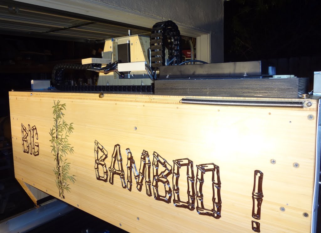
Thanks for the data Jerry that is very interesting! I think you should be really proud of getting that level of rigidity from a wood machine (OK it's "grass" not wood) especially as the machine is large and large machines will flex more than small machines.
-
02-26-2012, 03:52 AM #188
Registered
- Join Date
- Aug 2011
- Posts
- 999
Better Late than Never..
I reinstalled some Finite Element software that I had for a while (I had to go back to Windows XP on a laptop because incompatible with Win 7) and analyzed the behavior of my gantry under machining load. That is of course a bit late for my machine because it is already built and more an academic/fun exercise for various reasons: The non-isotropic (means directionally different) properties of plywood and the backlash/flex of the linear bearings can not be modeled with this software (older COSMOS version). But I did use the proper stiffness for the lumber, the aluminum bearings and the steel rails.
Nevertheless the result is quite interesting, not to mention looks pretty cool (for a mechanically minded nerd like me).
The boundary condition was a sliding surface on the x-rails and the ball nut mount fixed in x-direction. The load was 1000 pound forward on the lower Y-bearings and 500 backward on the upper ones to simulate about 500 pounds on the bit (yes I know this is not going to happen).
The deformation is then exaggerated by 100
[ame=http://www.youtube.com/watch?v=oz51eHgr0F4]GantryFEA.avi - YouTube[/ame]
Displacement:

Stress:

Strain:

-
02-26-2012, 04:22 AM #189
Registered
- Join Date
- Jan 2008
- Posts
- 853
Would you say then that the single-thicknesses of ply supporting the Y rails is the cause of the flex on rails?
-
02-26-2012, 04:29 AM #190
Registered
- Join Date
- Aug 2011
- Posts
- 999
Yes, I would say so and yes, you don't really need an FEA to guess that ;-) Originally Posted by PaulRowntree
But keep in mind, under reasonable machining loads of 10-30 pounds the deflection is calculated to be only 1/1000" which is remotely consistent with my measurements and actually very good. The whole bearing train and Y-Z-plate gadget contributes much more to the flex.
-
02-26-2012, 02:58 PM #191
Registered
- Join Date
- Oct 2005
- Posts
- 2392
An obvious improvement would be to bolt a metal plate under the gantry horizontally, and through bolts bolting the lower rail through the bamboo into the metal plate. The main down side will be the increase in weight.
Personally I think your machine is plenty rigid enough for the desired goal of machining wood so why bother? If you wanted a super-rigid machine for cutting metal you could invest some of this engineering time into designing/making a machine out of metal.
-
02-26-2012, 08:26 PM #192
Registered
- Join Date
- Aug 2011
- Posts
- 999
Absolutely....I am not about to change anything and I am quite happy the way it is. I just like to tinker and since I got that software running again I tried it on the gantry model. But, if I was to build another machine (I heard that happens) I would definitely try to optimize the design with the FEA results before cutting any part. Originally Posted by RomanLini
While the software is over 10 years old it is still something I could not afford privately. I used it on a work project and back then it cost something like $12,000 with $1,500 annual upgrade fee. But when I changed jobs there was nobody left who knew how to use it and it was just sitting in my desk drawer. So I better put it to good use now.....
-
02-26-2012, 09:20 PM #193
Registered

- Join Date
- Feb 2009
- Posts
- 1290
I would be interested to see what my machine looks like modeled in your software...
Thank You.
-
02-27-2012, 06:01 PM #194
Registered
- Join Date
- Aug 2011
- Posts
- 999
If you can provide me a solid model of the aluminum extrusion (I believe you used 1545 size?) the risers and the steel plate as an assembly I can give it a try. You need to remove all details (bolt holes, small cutout, recesses etc) that are not essential for the mechanical behavior. Also, the various parts have to touch each other without gap and without overlap. I that case the software will calculate as if the 4 parts are fused together (not bolted at specific locations) at the touching surfaces. But the result usually comes quite close. Originally Posted by Drools
I can import Parasolid (.x_t), ACIS (.sat) and Step (.stp) files. I can not use surface model files like .stl, .obj, .wrl or similar. Iges solid model files (.igs) will sometimes work.
I can not promise it will work. The biggest issue is probably the meshing of the complicated 80/20 extrusion internal geometry. That takes a lot of finite elements to model and at some time the software may just give up.
-
03-05-2012, 03:33 AM #195
Registered
- Join Date
- Aug 2011
- Posts
- 999
Dust protection finished
I had a little more time last week to finish the dust protection for the 2nd x-axis rail/screw and the Y-axis. For the latter I did not not want to let the curtain wrap around the gantry and had it rather spool on shafts on the left and right hand side. The spools are held taut by fishing lines (80 lbs test) that are connected with a pulley and tension spring gadget in the front of the gantry. Works pretty well and all ball screws and linear rails (except part of the Z-rails) as well as the x-cable chain are now completely enclosed without loss of motion range like bellows.
Next step will be re-doing the spindle cooling/dust extraction air duct. I was not really happy with the first version; it was just a bit flimsy and did not look very elegant.
I also need to improve my Thien style baffle dust cyclone. Right now the filter bag clogs with very fine airborne dust in short time. I am working on a system like the domestic Dyson vacuums with a battery of small cyclones as a second stage for fine particles. If I get that to work I will post here sometimes.


-
03-05-2012, 03:46 AM #196
Registered
- Join Date
- Nov 2006
- Posts
- 1036
That dust cover on your gantry looks great! Can you post a movie?
-
03-05-2012, 01:26 PM #197
Member
- Join Date
- Apr 2007
- Posts
- 8082
That looks really slick. The material looks a lot like some landscape fabric I use around my raised plant beds.
CarveOneCarveOne
http://www.carveonecncwoodcraft.com
-
03-05-2012, 06:09 PM #198
Registered
- Join Date
- Jul 2006
- Posts
- 102
The Dust cover looks really clever! Only problem, the first thing I thought when I saw it.. "Wonder where he got the black roll up blinds?"
Keep up the great work!
-C
-
03-05-2012, 06:15 PM #199
Member
- Join Date
- Apr 2007
- Posts
- 1955
Fascinating and beautiful build.
Thanks for the stiffness testing and FEA analysis - it is quite interesting.
I am not entirely certain of this, but from the reading I have done on various linear bearings, sometimes one rail is a master and the other is a slave. The master rail side is fixed, and would not have the adjustment nut. The ones with an adjustment would be on the slave side.
From the product descriptions, it seems like those glacern setups should be pretty stiff, supported rail, 20mm diameter. That isn't all that different than some other heavier duty setups, and definitely more beefy than many skate bearing setups.
-
03-05-2012, 08:22 PM #200
Registered
- Join Date
- Apr 2004
- Posts
- 141
I like that idea. Once I finally get to that point in my build, I was planning on doing almost the exact same thing ... But with actual roll-up blinds. Originally Posted by Miata2k

 Reply With Quote
Similar Threads
-
7 x 10 project started
By blades in forum Mini LatheReplies: 125Last Post: 01-25-2017, 05:27 AM -
CNC Project Started
By NotSqueaky in forum CNC Wood Router Project LogReplies: 8Last Post: 09-10-2014, 12:41 AM -
New Project Started
By Rumblebelly5 in forum Joes CNC Model 2006Replies: 1Last Post: 09-15-2012, 10:50 PM -
My 4x8 project has started
By MetalHead6263 in forum Plasma, EDM / Other similar machine Project LogReplies: 37Last Post: 01-31-2012, 07:30 AM -
Started new project
By rustamd in forum DIY CNC Router Table MachinesReplies: 55Last Post: 05-31-2009, 04:12 AM
