


Anybody else trying to use turbo cad/cam for generating lathe code??
I get a drawing done, then it refuses to select a starting point on my profile so I can get no further.
I have tried drawing traditional and just using the cam shape maker thingy still no luck.... Hellp:drowning::tired: any other programs now i have spent my money??
View Poll Results: Should I keep learning Turbo CAM/CAM
- Voters
- 4. You may not vote on this poll
Thread: Turbo CAD/CAM Lathe code
Results 1 to 8 of 8
-
09-24-2011, 10:08 AM #1
 Registered
- Join Date
- Feb 2008
- Posts
- 26
Turbo CAD/CAM Lathe code
-
10-22-2011, 04:07 PM #2
Registered
- Join Date
- Feb 2007
- Posts
- 9
I’ve used TurboCAD on the mill for a few years at home on V17 and have recently started using it on a ’91 Hitachi lathe my work acquired for cheap (free, our other store couldn’t figure out how to run it). My work then bought the latest V18 of TurboCAD/CAM to use for the Lathe (Which put me under a little stress that I had to figure it out now)
First of all let me say that the CAM portion of TurboCAD leaves a little to be desired, and I really don’t think that the CAM portion of TurboCAD/CAM has been updated since they first introduced it on V12, but I think for the money this might be the only way to go if you want a single program to do everything. (I’m sure I’ll get beat up for that remark, but I’ve tried some of the other programs recommended on these forums and haven’t yet found one that I would consider overall better)
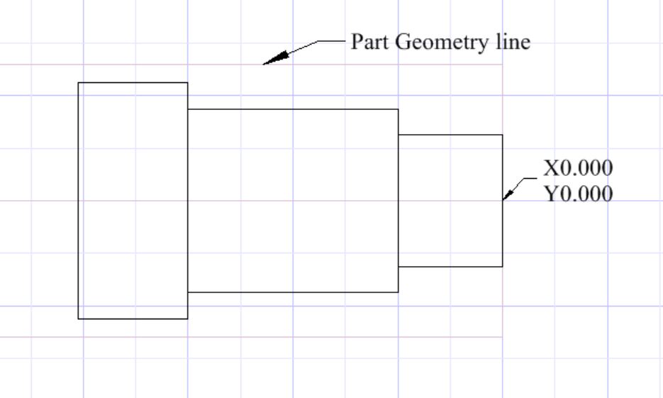
Anyway, as far as cutting for a lathe goes I noticed that you have to use one of the 2 setup machines (in the CAM setup Wizard; either the “Fanuc-Lathe” or the “Tormach-Lathe”) and modify them for your machine; if you try to save to a new machine name it won’t do some functions like threading for some reason. Next as you’re going through the setup wizard when you get to the “Part Geometry” the “Length” and “diameter” has to be the same size as the shaft you’re starting with.
Then when you draw your shaft and place it to be turned you have to put X0.000 and Z0.000 on the screen so that X is on the centerline of your shaft, and Y is also on 0.000. (You’re going to notice that X and Y in on the screen is backwards from the Lathe X and Z, “Y” on the screen is the “X” axis on the Lathe and the “X” axis on the screen is the “Z” axis on the lathe)
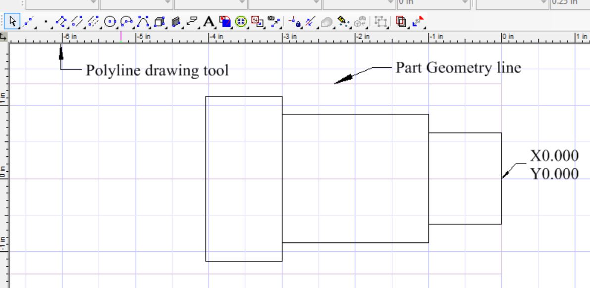
After you put your shaft on the screen, what I do is draw a “cutting line” with the polyline tool and the most important part is that the cutting line needs to intersect the part geometry line. (To draw simple shafts I just make them out of separate blocks, and then put the radiuses in after I draw the cutting line)
I’m going to try to post some screen captures to try to show the process that I use, this may not be the “right” way to do it but it works for me.
If you've noticed this polyline doesn't look the same as the shaft in the previous pic I put the radiuses in after I draw the polyline (I've hidden the original "shaft" after I traced it with the Polyline)
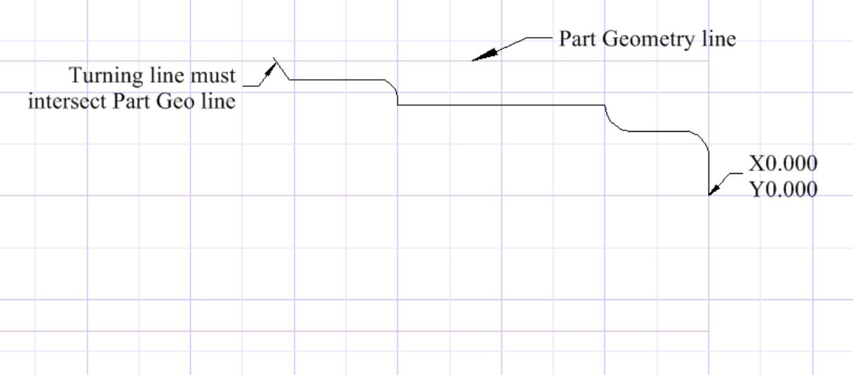
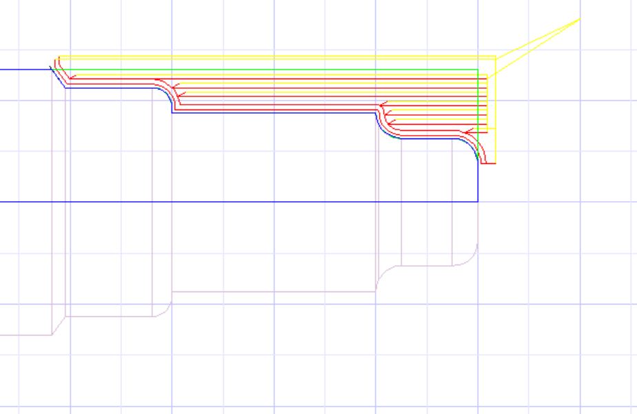
Then you use the turning tool and click on the part first, and then the hashed area you want to remove. (Note that if you can't get it to do anything then your "turning line" may not fully intersect your "part Geometry" line)
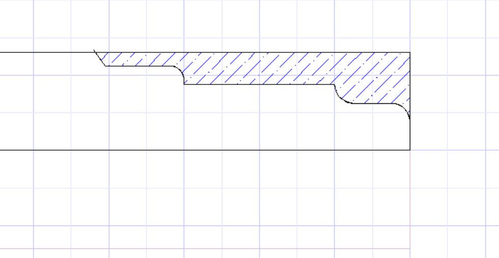
After that you hit the Finish button and it makes your cut.
Hope this helps, this is just the way I do it and may not necessarily be the way the "experts" do it
-
10-23-2011, 11:34 AM #3
Gold Member
- Join Date
- Aug 2011
- Posts
- 2517
I'm playing with a trial version of V18 right now.....
the problem is very few jobs are that simple. what about drawing complex partial curves that are tangent to other lines or arcs. the polyline tool can't handle that because it only draws straight lines and if the part is not drawn as a single polyline the CAM does not accept it and says the contour of the part does not intersect the boundary even though the lines do cross the boundary.
I got around it by drawing it using lines and arcs and trimming/editing like any other CAD program, then create the polyline by chaining the lines/arcs (using the CAM menu). then all of the lines/arcs MUST be deleted or it tries to select the lines even if the polyline is selected thus resulting in the error about the contour not intersecting the boundary etc
you're right about the CAM not changing. I installed V15 and V18 and the CAM side of it is identical. Not too good!
-
10-23-2011, 03:36 PM #4
Registered
- Join Date
- Feb 2007
- Posts
- 9
Yeah, I actually was emailing back and forth with Bob Mayer who is one of the main founders of TurboCAD (they wanted to use one of my YouTube Videos for their advertising), and he seemed to imply that they weren't really that interested in the CAM area unless they could get more public interest of it built up, so I’m trying to do my small share to build it up LOL.
You can do some pretty complex one line shapes with the polyline, and it can draw arcs, I found out while doing my CNC milling that it was always best to make a single polyline around all of my cuts to avoid errors when trying to machine the parts. I'm not sure about what the lines you were talking about, but here's some .jpgs of more complex shapes with milling parts
First was an alternator bracket for my street rod, the OD, the spacer and the slot were all made with 3 single polylines
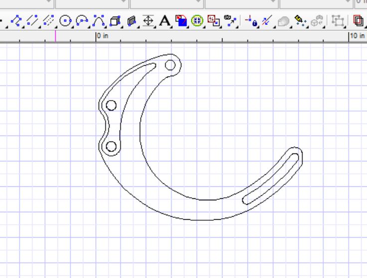
I’ll show on a linkage arm that I made and how I trace it with the polyline, first is the linkage arm drawing:
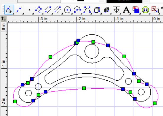
Next I select the polyline tool and usually right click and use the “snap to->vertex” mode to snap to the ends of each circle. After you’ve snapped on the vertex of the first circle right click to open the pull down menu and go down and click the “arc segment”, then “snap to->vertex” of the end of the circle. You’ll notice on the pic below that the polyline is going all over the place (and many times it even looks a lot more confusing than this) but keep going around the cutting edge not worrying about where the arcs are going. (You’ll usually end up having to select between "arc segment" and "line segment" many times to complete your cutting line)
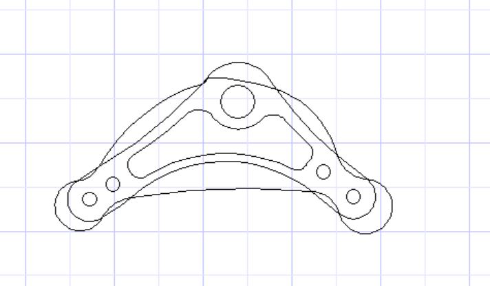
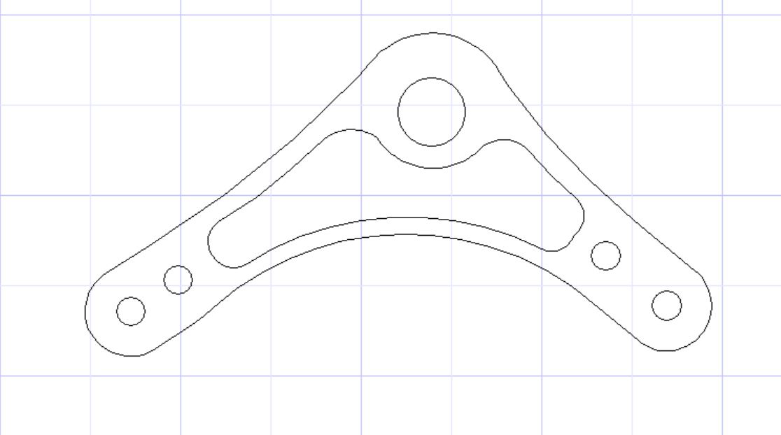
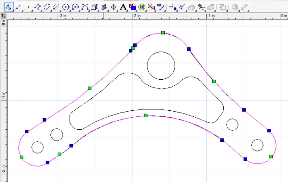
Next use the Node edit tool (highlighted in the top left in blue in next pic) and select this wavy polyline that you just made and then grab the arc centers (green blocks) and use the “snap to->nearest on graphic” to pull the arc centers into place, (you may have to adjust the blue block positions also sometimes) resulting in the end cutting line being a single polyline (sometimes you may accidentally put an arc where a straight line should be and usually you can right click->”delete node” to make a straight line out of it, sometimes it won’t let you delete and you have to start the polyline over, but once you get a hang of the polyline tool it’s very quick to make this cutting line.
Ending up with your single polyline cutting line, I don't think there's any type of a complex line that can't be traced like this, but I could be wrong. Like I said earlier these pics were from my mill projects, but the lathe stuff seems to be very similar with the main difference is just working with half the part on its side instead of the whole part.
That all being said, again this is just what works for me and is not necessarily the way an "expert" might do this.....
For anyone whos interested here's a small "customer success story" writeup by TurboCAD
http://www.turbocad.com/Company/Cust...3/Default.aspx
-
10-24-2011, 09:26 AM #5
Gold Member
- Join Date
- Aug 2011
- Posts
- 2517
hmm that looks interesting. how does the node edit affect the accuracy of the dimensions? most of the stuff I machine is tied up to +-0.001". Manual editing does not sound like a good idea to maintain accuracy?
-
10-24-2011, 12:44 PM #6
Registered
- Join Date
- Feb 2007
- Posts
- 9
As long as you make sure that all your vertexes are snapped to the vertexes on your original part I haven't seen any variation at all (only do it by snapping to the original vertexes), you can roll the TurboCAD screen in with the wheel on your mouse and see instantly if your new cutting line varies any at all from the original line. (when you roll the TurboCAD screen in it will show resolution down to about 1/2 of a tenth of a thousanths or something like that, and if your line is off at all it will show 2 lines)
I really wouldn't call it manual editing because if done right and snaps are used for everything you haven't changed any dimensions, only traced the dimensions already there.
If you do lines with multiple arcs be very careful to hit the beginning and end of every circle.
-
10-25-2011, 01:50 AM #7
Registered
- Join Date
- Feb 2007
- Posts
- 9
I just noticed one thing to be aware of if you're using V18 and a previous version of TurboCAD, anything drawn up in V18 won't open on my V17, I just emailed home a drawing from work and it won't open up using the .tcw file, I'll have to look tomorrow and see if there's another extension I'll have to use for previous TurboCad versions or try a .dwg file or something
-
10-25-2011, 08:27 AM #8
Gold Member
- Join Date
- Aug 2011
- Posts
- 2517
that's normal. newer version files can't be opened on older version programs.

 Reply With Quote
Similar Threads
-
CNC Lathe G code G73 / G83
By nelsonrb4 in forum G-Code ProgramingReplies: 9Last Post: 06-06-2022, 11:44 AM -
Turbo CAD CAM G code Saving
By peelmachining in forum Uncategorised CAM DiscussionReplies: 0Last Post: 02-10-2010, 09:36 AM -
cam to g-code for cnc lathe
By slow_rider in forum CNC (Mill / Lathe) Control Software (NC)Replies: 0Last Post: 10-21-2006, 07:16 PM -
CNC Lathe Threading G-Code HELP>>>>
By vtech99 in forum CodingReplies: 2Last Post: 08-26-2006, 09:30 AM -
fanuc 11 lathe g-code
By bobcor in forum FanucReplies: 3Last Post: 08-20-2006, 08:16 PM
