


So first it started with my inital design, which had some serious flaws....So here is the current design, although the gantry is currently a work in progress.
The goal of the machine was to design a CNC that met the following criteria:
Machine Size: 20"x20"x19.5"
Travel Distance: Goal was 14.5 x 16.5 x 7.75, but that's a work in progress.
Materials: Aluminum and Steel
Precision Goal: .001"
Budget: $800 (lol)
Its purpose, aside from cutting things, is to allow me to create small aluminum prototypes for other projects - It'll also be doing PCB's and other wood / polymer jobs. It was designed to be a small "desktop" unit but I'm starting to doubt its 100+ lb foot print will sit well on my glass top desk.
I apologize for the ****ty phone pictures, I sold my DSLR to fund this project haha
It was designed bottom-up (dumb modeling) in Solidworks 2011. But I'm now considering re modeling it in Catia V5 using relational (top-down) methods.
The first thing I tactled was the base, it's made of "8020 T-Slotted" extrusions. Which are 6061-T6 Aluminum. I took this inspiration from a lot of other DIYers on CNCzone and internet in general - and it was a good decision. Very cool stuff.
The vertical supports (I call them uprights) are made from 5/8" hot rolled steel plate and were a HUGE pain in the rear to cut and shape.
Because of there thickness, holes 1/8" away from the actual surface were cut at directional changes in the design (aswell as interior cut out). Then outlined using a high precision process involving a straight edge and a sharpie.
Then, the dots were connected using a band saw. About 4 hours later this essentially left me with a rough outline of the shape with 1/8" of extra material. Then these pieces were placed in the CNC and the edges were rounded off and other details added.
Roughly 9 hours after the CNC's had their way with them. They were done!
So now the entire base structure is completed.
The linear rails seen in the picture were purchased as 1 long continuous 7' length, so they were cut down to size using a grinder... But unfortunately now the hole patterns are completely inconsistent and a way needed to attach these to the 8020 base structure.
So using a C02 laser at the university, 3/8 acrylic plates was cut and will be used as "adapter" plates to attach the linear rails in the X and Y axis.
So here is where i currently am in the project....Its now time to begin purchasing aluminum plate to create the gantry and Z axis systems.
But first i'll need to make some changes to my design. Just a warning, this is going to be a LONG project as I'm currently a senior mechanical engineering student at UCSD and i'm pretty busy with school and work.
But feel free to leave comments and advice
Results 1 to 20 of 22
-
10-31-2011, 04:23 AM #1
 Registered
- Join Date
- May 2011
- Posts
- 0
Mint's Aluminum/Steel Build thread.
-
10-31-2011, 04:25 AM #2
Registered
- Join Date
- May 2011
- Posts
- 0
Reserving space
-
10-31-2011, 04:27 AM #3
Registered
- Join Date
- May 2011
- Posts
- 0
Reserving space...again!
-
10-31-2011, 06:24 AM #4
Registered
- Join Date
- Jul 2005
- Posts
- 163
Looking pretty good so far, Fresh. Kind of wondered why, if you have access to a CNC mill, you didn't profile out the steel parts, as well as drill them out? It would have been much less work for you, and could have been done in less than 1/4 the time.
Also, I think you'd be better off to replace the acrylic with some aluminum. I'd be concerned about the accuracy you can get with acrylic in the structure of the machine. I realize it's thick, but it will still flex more than aluminum will.
Good luck with the build!
-
10-31-2011, 06:31 AM #5
Registered
- Join Date
- May 2011
- Posts
- 0
Hey thanks for the comments. Originally Posted by DSpeck

I've done a bit of calculations for the acrylic parts and since the acrylic parts are mainly just going to see loads normal to there surface.... The young's modulus for acrylic is plenty strong enough for the application they're in. I'll replacement with aluminum parts once the machine is made too.
I worked at an on-campus machine shop last year so i had access to the CNC machinery...but this year i dont have access to a mill that works well with my schedule. Where as i have nearly 24/7 access to a laser cutter that'll cut acrylic, so some parts will have to be acrylic for now.
-
10-31-2011, 06:51 AM #6
Registered
- Join Date
- Nov 2006
- Posts
- 1036
My small fixed gantry router has a base similar to yours. http://www.cnczone.com/forums/diy-cn...ry_router.html
I used 3/8" x 3" cold rolled steel for my adapter plates because I wanted to securely fasten my rails to the adapter plate. Not sure about the strength of tapped holes in acrylic. I did get the steel cut to a specified length. Only operation I had to do was to drill and tap the holes.
BTW, small world, my son is in his 3rd year at UCSD.
Some photos:
-
10-31-2011, 06:53 AM #7
Registered
- Join Date
- May 2011
- Posts
- 0
Yeah the tapped holes in the acrylic are my main worry too -- they're pretty weak...I figure they should last long enough to make aluminum ones once my machine is running...but until then. Originally Posted by DonFrambach
-
10-31-2011, 02:24 PM #8
Registered
- Join Date
- Aug 2008
- Posts
- 409
Are you only going to use 2 bearing blocks on your table instead of 4? Are you worried about the table flexing or bending when machining at the edges/ends of the table?
-
11-01-2011, 12:29 AM #9
Registered
- Join Date
- Oct 2005
- Posts
- 2392
That looks like a nice strong build with the 5/8" steel side plates!
If you moved the table rails closer together you will gte much less table flex and less table skew as well.
I used acrylic sandwiched between metal in a few places on my CNC machine, it is very strong in compression and threads tapped into acrylic are also surprisingly strong. One BIG problem however is that its thickness vaires a lot, you should measure with a micrometer or good vernier caliper in a few places as the thickness of 10mm acrylic can vary as much as 0.5mm over a few inches. All the acrylic in critical spots on my machine (like under bearing rails) was surfaced flat and to an exact thickness.
-
11-13-2011, 08:58 AM #10
Registered
- Join Date
- May 2011
- Posts
- 0

not sure how to edit my first posts...looks like the option is missing..
Anyway, this week i managed to drill the holes into my linear rails so that they'll properly mate my acrylic adapter plates.
Just ordered a 12x12x.75 plate of aluminum for the gantry... So more to come.
however, i've been debating...Should I go with a 1.5kW Chinese spindle and inverter, or go with a 1hp bosch handheld router with a super PID?
Both are around the same price, but im not sure on the chinese spindle's reliability
-
01-29-2012, 10:13 AM #11
Registered
- Join Date
- Jul 2011
- Posts
- 0

Anymore progress on this? I am planning a build that is very similar to this sometime this year and just wanted to see how far its come along.
-
01-29-2012, 10:17 AM #12
Registered
- Join Date
- May 2011
- Posts
- 0
Yes - sorry for the long time with no update been busy with school.
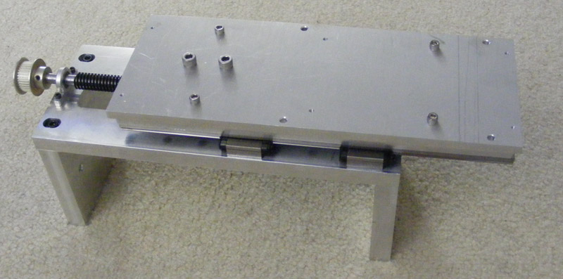
I've assembled most of the Y axis and machined most of the plates needed for it.
I've also turned down my ACME screws... Here is my most recent pic...but this doesnt include the screws. I'll have more pics coming in the next few weeks as i finish machining more components.

-
01-29-2012, 03:34 PM #13
Registered
- Join Date
- Oct 2005
- Posts
- 2392
Nice to see an update! I was wondering what happened to this nice build.
-
01-31-2012, 08:55 PM #14
Registered
- Join Date
- May 2011
- Posts
- 0

So here is the newest image with a decent camera. As i've said I've got the lead screws turned down - however on some of them i turned them down a little too much (maybe a few thou too much... So i guess my only option is to locktight them into place. Should be fine...i hope
-
01-31-2012, 09:04 PM #15
Registered
- Join Date
- Aug 2008
- Posts
- 409
I had the same issue on my leadscrews, a couple thou to small, Loctite retaining compound has worked for me, going on 3 years.. it can fill small gaps and drys hard. Originally Posted by FreshMint
-
05-18-2012, 08:18 AM #16
Registered
- Join Date
- May 2011
- Posts
- 0
Thanks for this info! I bought the stuff and applied it and it seems to be holding tough, but the true test will come when I have motors in my machine! Originally Posted by Phife
So here are some pictures for this slow moving project!
Made some custom pillow blocks, and finished the Y/Z Gantry! Almost done with all the structural/mechanical stuff, i'm slowly getting ready for the electrical stuff now!
Sorry for the slow progress to anyone who is following this.


Almost forgot!
here is an updated CAD picture! Even modeled the 2.2KW Spindle i'm hoping to use!

-
05-18-2012, 11:53 AM #17
Member
- Join Date
- Dec 2007
- Posts
- 2134
That's a brilliant effort you've made! Great looking machine, how did you go getting the machining and parts aligned perfectly?
cheers,
IanIt's rumoured that everytime someone buys a TB6560 based board, an engineer cries!
-
05-19-2012, 07:29 PM #18
Registered
- Join Date
- May 2011
- Posts
- 0
Most of these parts were made inside a machine shop with full sized mills, and lathes... Aside from that, Some pieces are designed with oversized or ovaled holes so that adjustment and fine tuning can be made in case something isn't lined up perfectly. Originally Posted by aarggh
Thanks for the compliments!
-
05-20-2012, 09:09 PM #19
Registered
- Join Date
- May 2011
- Posts
- 0
So I slapped together my design for a integrated stand. Its made of 8020....I am a bit concerned with the CG being too high now though. But I think after I add a reservoir for for the spindle's water toward the bottom it'll help a lot...Here is a picture

Also if any of you want more info or pics feel free to check out my site.
-
05-20-2012, 10:59 PM #20
Registered
- Join Date
- Oct 2005
- Posts
- 2392
As a suggestion I would lower the base rails right down near the casters, which can then be used to support a flat shelf on the bottom (making the stand more like a cube).
Then if you screw 3 walls onto the sides of the stand you get a strong box that will also be useful to hold stuff like your electronics or water cooling etc. Also you could easily add a hinged door to keep all the nasty cutting chips out of it.


 Reply With Quote
Similar Threads
-
My first build Steel & Ali
By Action-KAT in forum DIY CNC Router Table MachinesReplies: 20Last Post: 12-07-2012, 06:43 PM -
Build Thread 1
By groswald in forum Momus Design CNC plansReplies: 126Last Post: 11-11-2011, 07:09 PM -
Mint's Build Aluminum/Steel Build thread.
By FreshMint in forum Maintenance DIY DiscussionReplies: 0Last Post: 10-31-2011, 04:18 AM -
Mungee's All-Steel CNC Build Thread
By mungee in forum CNC Wood Router Project LogReplies: 10Last Post: 09-24-2011, 01:48 AM -
My new steel aluminum CNC Build Log
By drRobutik in forum CNC Wood Router Project LogReplies: 12Last Post: 07-21-2011, 01:18 PM
