


Concept
Ok, this is something I have been thinking about for a while, and had mentioned in the electronic home switches thread;
http://www.cnczone.com/forums/open_s...made_easy.html
Since the electronic Hall type home switches can sense machine position to better than 0.001" I wondered if it was possible to use the home switch to automatically measure the backlash of the machine, which would enable the machine to automatically change its backlash compensation settings to adjust for wear or for thermal expansion.
I have recently been using my small plastics milling machine to make a few small parts that need tight tolerances, and have been bugged by some thermal expansion issues where my leadscrews grow a couple thou in length when they get warm, so features on the part are displaced by 0.002" or so. That was fixed easily enough by changing my homing routine to re-home frequently during the job and this compensates the thermal expansion.
Backlash
However my backlash also changes a bit when warm. Measuements (I'll post more on the measuring techniques later) show a cold backlash around 0.0025" and 0.002" for my X and Y axes respectively. But when the leadscrews warm up they expand and the backlash drops to half that, even a bit less, both axes come in around 0.001".
Using the home switch to measure backlash?
This works based on one concept; That the electronic home switch which we know has a reliable ON position detection, would also have a reliable OFF position.
The Hall switch has hysteresis, this term means that once the magnet is close and the switch turns ON, the magnet must be moved away a bit before the switch turns OFF. This hysteresis is designed into the switch, and I assumed the turn OFF position was also thermally compensated etc like the turn ON position. Testing looks promising at this point.
How does the switch do it?
Well it is simplicity itself. The magnet is brought close until the swtch turns ON, this point is recorded.
Then the magnet is moved away a couple mm until the switch turns OFF again. This position is recorded.
The distance between the 2 positions I called the "sensor backlash" for lack of a better term. This distance includes BOTH the actual sensor hysteresis AND the machines mechanical backlash (as the machine has reversed direction).
Results 1 to 9 of 9
-
11-11-2011, 05:20 PM #1
 Registered
- Join Date
- Oct 2005
- Posts
- 2392
Auto backlash sensing with electronic home switches!
-
11-11-2011, 05:37 PM #2
Registered
- Join Date
- Oct 2005
- Posts
- 2392
But how does that work?
The "sensor backlash" is easy to measure automatically, with something like a homing routine or even as part of the normal homing routine.
Because it contains two components;
1. The electronic Hall switch/magnet hysteresis (should remain constant)
2. The actual machine mechanical backlash (the remainder)
if the first component can be quantified once, then every time the test is performed the remainder of the value must be the machine's mechanical backlash.
Quantifying the Hall sensor hysteresis
Well this process actually quantifies the machine backlash, and we work out both component 1 and 2 at the same time.
The easiest way is using a dial gauge, a tool used on metalworking Lathes and is commonly available for $40 or so.
Using the dial gauge to measure machine backlash
I used the setup seen below, which is just a metal block screwed down to my CNC machine table, and the magnetic base hold the dial gauge in position.
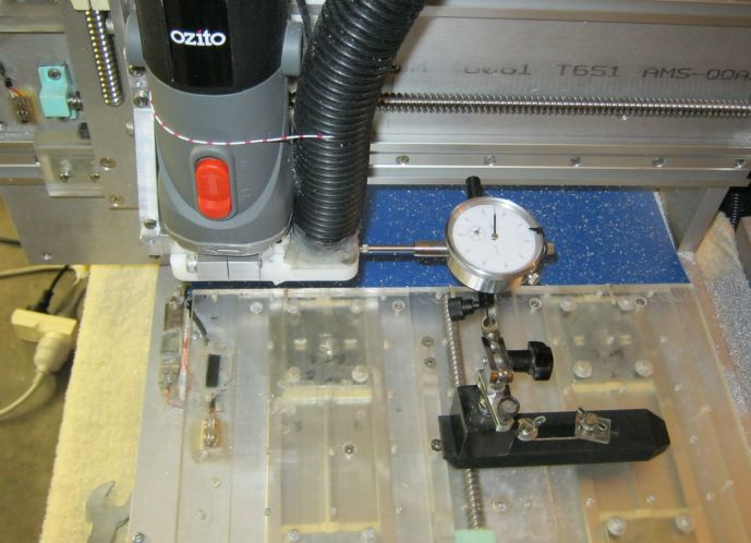
As the X axis moves right-left this moves the dial indicator. My dial gauge is just on 0.001" divisions (it's a cheap one), but it still shows pretty well to 0.0002" (ie; one fifth of a thou, maybe one tenth of a thou if I get fussy).
Measuring backlash has issues...
I knew from previous backlash testing on my machine there are some issues. The backlash should be tested in a "settled" position, as the vibration of your router and stepper motors will settle the position a certain amount.
I did the settling by pushing the axis hard with my hand, then releasing it and tapping it VERY lightly with a plastic screwdriver handle a few times. Then pushing hard the other way, and after releasing and tapping again checking the dial gauge.
Backlash on my machine at this point (machine is cool);
X = 0.0025" = 0.06 mm
Y = 0.0021" = 0.05 mm
That made me fairly happy, the machine has plastic leadnuts and there seems to be no wear at all after many months of use (although intermittant use).
-
11-11-2011, 05:59 PM #3
Registered
- Join Date
- Oct 2005
- Posts
- 2392
Software measures the Hall sensor backlash
I write my own PC CNC software so I just coded this function into my popup form that does XY homing procedure.
However people using Mach3 and EMC2 software should be able to do this fairly easily with a macro, very similar to the homing macro you are probably using now.
This form below looks crude, I have made no attempts to make it pretty!
At the top it shows the usual XY homing values, where the machine has homed to within 0.01 mm of the correct X and Y values. (The "error of 1" is showing 0.01 mm error detected on the Y axis, this is about the limit of my Hall switch setup, to the nearest digit and the smallest digit is 1, which is 0.01 mm).
The important stuff is at the bottom! The Hall sensor backlash is shown, X = 205 (2.05 mm) and Y = 314 (3.14 mm). Those two values state how far the axis had to move back to counter the Hall sensor total hysteresis (which includes machine backlash).
Putting it together!
So now it was easy! All I did was subtract the machine's measured actual backlash, and get a value which is not shown on this form but is used internally.
Now that internal value (I called it "component 1" above) is known, and anything above that value is the exact backlash of the machine itself.
Testing
Testing looks promising at this point. I did a couple hours testing actual backlash with the dial gauge, with the machine varying from cool to warm, and at the same time kept checking the auto backlash measurment.
It responded quite well. My X backlash is about 0.0025" when cool, and is about 0.0013" when warm. I could see this on the dial gauge, and it was also reflected quite well in the homing procedure (auto backlash measurement procedure).
Resolution
Resolution is a small issue here, my system at the moment only reports in 0.01 mm resolution (about 0.0004") so any reading from the hall switch is to the nearest 0.01 mm, and can differ by 1 count from time to time.
I think part of that is because the steppers make vibration when they turn, and it's not hard to cause a 0.01 mm movement error on something that is vibrating! One day I will test with a spring or something attached to the axis, to try to remove the drift that may occur from vibration.
However averaging the backlash measurements over a few tests gives good predictable values. As it should if there are no other problems, which fortunately seems the case.
Making the machine change its own backlash compensation!
I'm not sure how this would be coded into Mach3 or EMC2, but on my software it was quite easy. Once the measurment procedure tests the backlash values, it just enters them into the backlash compensation variables.
I'm very happy with this! Now when my machine gets warm in use, I can re-home with one button push, and it re-zeros the X and Y axis and ALSO re-measures the actual X and Y backlash, and changes the backlash compensation values!
Another benefit will be that I can see the backlash values everytime it homes, and not only will it compensate for wear as the wear occurs but I can SEE the wear as numbers on the homing screen.
That's all for now. I'll do some more cut tests soon and post more details.
-
11-11-2011, 06:10 PM #4
Gold Member
- Join Date
- Apr 2006
- Posts
- 3498
Roman, You are amazing guy. I am very impress and really pretty interested in your CNC software that you have made for your machine. Each day i wish to see the screen shots of the software may be someday you will post.
I hope Gerry will look at this method and will be able to corporate this feature in his screen set 2010
http://free3dscans.blogspot.com/ http://my-woodcarving.blogspot.com/
http://my-diysolarwind.blogspot.com/
-
11-12-2011, 09:14 AM #5
Registered
- Join Date
- Oct 2005
- Posts
- 2392
Hi Khalid, thanks for the nice words!
Nah you don't want my CNC software it's pretty crude! The only good thing is that it communicates with the microcontroller brain in my CNC machine, so they work as a team. The micro in the machine handles all accelerations etc in real time for great smoothness, the PC software just tells the machine where to move to.
You made a great point that Gerry (or another mach3 macro expert?) might be able to put the auto-backlash feature into Mach3 for people to use. There are quite a few people now using the electronic home switches, and those people might want to see their backlash values too. Sorry I don't know anything about Mach3 coding or I would do it.
Backlash averaging update
I spent an hour today doing some more tests and changed my software a little. It now does the backlash test 8 times for each axis X and Y, and averages the result. The result is now nice and constant and reliable.
Total backlash testing (16tests) now takes about 35 seconds, which is no big deal and I can still do it on the spot between loading jobs etc.
-
11-13-2011, 02:58 PM #6
Community Moderator
- Join Date
- Mar 2003
- Posts
- 35538
The majority of Mach3 users running CNC routers are either using spring loaded anti backlash nuts, or r&p with spring loaded pinions, and backlash isn't an issue.
Art, Mach3's developer, has always maintained that eliminating backlash is a far better option than using software backlash compensation, and I tend to agree.
So don't count on me doing any work with this.
But please don't stop giving innovative options to the community. I personally just have no use for this one. But I can't be without the SuperPID and EH switches.
Gerry
UCCNC 2017 Screenset
http://www.thecncwoodworker.com/2017.html
Mach3 2010 Screenset
http://www.thecncwoodworker.com/2010.html
JointCAM - CNC Dovetails & Box Joints
http://www.g-forcecnc.com/jointcam.html
(Note: The opinions expressed in this post are my own and are not necessarily those of CNCzone and its management)
-
11-13-2011, 03:45 PM #7
Gold Member
- Join Date
- Apr 2006
- Posts
- 3498
Hmm.. then either i have to learn the macro and screensets things or i have to post the contents of this thread in Mach3 forum with the permission of Roman:argue: Originally Posted by ger21

The second method seems lot easy to post in Mach3 forum and let others(experts) do the work..:stickpokehttp://free3dscans.blogspot.com/ http://my-woodcarving.blogspot.com/
http://my-diysolarwind.blogspot.com/
-
11-13-2011, 04:38 PM #8
Community Moderator
- Join Date
- Mar 2003
- Posts
- 35538
I'm not sure you can do this easily in Mach3 without additional hardware.
When you are homing in Mach3, the axis moves until the switch is triggered, then reverses and backs away until the switch opens. The opening point is your home position.
If what I read is correct, you need both the switch closing and opening positions. Mach3 doesn't give you that information, afaik.
I'm far from an expert, but I can't think of an easy way to do it in Mach3.Gerry
UCCNC 2017 Screenset
http://www.thecncwoodworker.com/2017.html
Mach3 2010 Screenset
http://www.thecncwoodworker.com/2010.html
JointCAM - CNC Dovetails & Box Joints
http://www.g-forcecnc.com/jointcam.html
(Note: The opinions expressed in this post are my own and are not necessarily those of CNCzone and its management)
-
11-14-2011, 02:36 PM #9
Registered
- Join Date
- Oct 2005
- Posts
- 2392
Thanks for your input Ger21 (and Khalid too).
Looks like Mach3 already does what is needed in the procedure, ie find both opening and closing poiints, but it would need to actually make both numbers available.
Khalid- feel free to discuss and/or copy any of this thread onto the Mach3 forum, provided of course that it does break any of their rules.
Ger21- Even anti-backlash nuts usually run at 1 or 2 thou of backlash when measured at the axis, similar to my machine. At least this method would show if the anti-backlash nut was failing/wearing or if something had come loose.
I'm still doing testing on my machine, I actually found an anomaly where the backlash is small when very cold, then gets larger as the machien warms up, then gets smaller again when the machine is quite warm. Tricky hey? It's caused (I assume) by the different rates of thermal expansion of the metal leadscrews and plastic leadnuts.

 Reply With Quote
Similar Threads
-
Electronic home switches made easy!
By RomanLini in forum Open Source CNC Machine DesignsReplies: 1242Last Post: 08-01-2021, 10:25 PM -
NCStudio Question - Auto Tool Sensing
By robbec in forum Chinese MachinesReplies: 17Last Post: 02-12-2016, 02:58 AM -
NCStudio Question - Auto Tool Sensing
By robbec in forum Chinese MachinesReplies: 0Last Post: 05-14-2011, 08:33 AM -
The relationship of limit switches to home switches.
By MikeAber in forum CNC Machine Related ElectronicsReplies: 4Last Post: 11-04-2004, 08:28 PM -
Home switches and limit switches.
By ynneb in forum CNC Machine Related ElectronicsReplies: 5Last Post: 04-08-2004, 11:32 PM
