


Well, I started off building a Joes with full intentions of doing it all by hand. However, the weekend killed off that idea. I started to cut up my MDF for each piece only to find out my crap woodworking equipment didn't do that well. Then again, what can you expect from the likes of GMC and family.
So after some head scratching I decided to go with my original idea and build a throw away machine whose sole purpose in life will be to teach me about putting one together and for cutting out it's replacement in the form of a Joes 2006.
So with some of the pieces of my Joes already purchased I came up with a way to do this build spending as little extra dollars as possible. It will be a mish mash of ideas from Joe, Lionclaw, JGRO and buildyourcnc. I started today by going to Bunnings and buying a hollow core door which I promptly cut down to the approximate length of a Joes machine so I could use the 25 NB pipe I bought. A hollow core door BTW is basically a cheap torsion box so I thought that would make a good base.
I then remembered a method found here (sorry, can't remember who came up with it) of attaching the pipe so I cut up what 30x30x3mm aluminium I had and after thinking for a bit screwed it to the side of the base. The pipe will be screwed/bolted to this making the whole thing rock solid. The pics show the base as it is being built, it is currently on it's "back" while I mounted the pipes and figured out where the holes in the ends would be. I bored the pipes holes oversize with a 35mm Forstner bit to give me a little wiggle room and it has all worked out fine... except for a couple of mistakes which I don't care about.
Tomorrow I will carry on with the gantry parts and the Z-axis parts while I wait for my bearings to arrive for my trucks. I grabbed just enough 30x30x3 mmm ali from Bunnings to do the bearing trucks so at least I can have them all drilled for when the bearings get here.
Anyhoo, Ill probably updated this as I go along. As least I am building something I suppose
Cheers
Bruce
Thread: My Bitza Interim Build
Results 1 to 17 of 17
-
12-06-2011, 02:16 PM #1
 Registered
- Join Date
- Nov 2011
- Posts
- 211
My Bitza Interim Build
-
12-07-2011, 06:09 AM #2
Registered
- Join Date
- Nov 2011
- Posts
- 211
Got a little more done today. The pipes are secured to the base now and the ends fit fine. I also got the gantry sides cut (based on the JGRO part) and cut the slots for the bearing trucks, but.....
I officially hate Bunnings. I had a section of ali angle I bought from Capral Aluminium a while ago, they call it 30x30x3. I used that to measure the width of the dados into which the trucks sit. I dadoed both sides of the gantry, getting them all lined up perfectly. The Capral ali fitted perfectly, snapping into place nicely. I then cut a piece of the 30x30x3 ali I got from Bunnings only to find it is smaller then the same stuff from Capral. So I am going to use the Bunning one to practice making trucks with and I will go get a 6.5 meter length of the Capral stuff next week so I can make my real ones.
All the bearing trucks in this machine will be the same size a Joes machine requires so I can use them on that when the time comes.
Anyway, back to the gantry. I managed to cut up the various bits of the gantry (all of them that make up the gantry as a whole) but I can't put it together or cut the cross pieces to size until I get my skate bearings. Once I have those I can pretty much get the machine to the stage where it needs motors & electronics. I decided against buying from vxb as they would not be able to get them here before xmas. I am going with ABEC 5 bearings from a skate shop in Queensland, they have them for $10.00 for 8 so I will buy 4 sets from them. I only need to find the R8-ZZ 1/2"x1/8"x5/16" bearings locally now so I can make and mount my bearing carriers for the lead screws.
No piccies today, just lots of MDF dust instead.
Cheers
-
12-16-2011, 05:55 AM #3
Registered
- Join Date
- Nov 2011
- Posts
- 211
OK, been waiting on a few things to arrive so I can continue and everything I ordered has arrived:
All my bearings, both skate and 1/2 leadscrew bearings. All of these were sourced within Australia, the closest being 5 minutes walk from me! The skate bearings were made up from 32 from Queenland (8 @ 10.95) and 16 from the local guy. The 1/2 ID bearings were also from him @ 4.50 each x 6
Leadscrew shaft collars. Again from the 5 minute walk place, $1.50 each x 6.
1/2" 6tpi ACME Rod x 12 feet - $85.56 including GST. Sourced locally within my suburb, 2 minutes drive away. They didn't have immediate stock so they shipped one up from Adelaide and it arrived taped to a very larger hunk of wood in perfect condition. I will be making my own anti-backlash nuts from the chopping board I bought on ebay, I got the required size for the pilot hole from the supplier so I can tap my own 6tpi ACME thread in the nuts.
Pretty much all my bolts, a combination of 1/4 & 5/16 bolts and nuts.
All my aluminium channel, didn't bother to go to Capral, just bought it all from Bunnings. Will use Capral ali when I do the next machine.
So with all that plus the MDF I already have I can start putting it together so it looks like a CNC machine. Early in the new year I will be ordering the electronics side of things and hope to be using the machine in anger by the end of January 2012.
Cheers
-
12-17-2011, 10:35 PM #4
Registered
- Join Date
- Jul 2009
- Posts
- 99
G'day Bruce,
good to see your collection of parts is coming together. Good luck with the build and keep us posted.
That's the same ACME thread that I've used on mine. How was the thread condition? Mine had the odd small bump here and there that I had to run a file over to clean it up a bit.
How do you tap ACME thread into the PE (chopping board)? I thought you'd require a special tap for that......or do you just fashion one from the rod you have? I'm interested in how yours turn out.- Craig.
my JOES2006 build thread - http://www.cnczone.com/forums/showthread.php?t=106995
-
12-18-2011, 12:12 AM #5
Registered
- Join Date
- Nov 2011
- Posts
- 211
Got my gantry sides done yesterday after 4 tries
 Was fighting with a way to mount them so I can measure the width of the bottom until I worked out a way to do it at midnight last night. Will take some pics today after I tidy up a bit.
Craig - Apparently it can be done, I have seen it a couple of times somewhere on here. I'll use an offcut and grind it down to look like a tap and then try tapping a thread. Just trying to be cheap right now, if it doesn't work I'll splash out for dumpster nuts. The thread on mine is prefect, no marks at all. It even survived hanging out the window of my Ford wagon, 12ft just didn't fit inside the cabin. Tied it to my passenger side wing mirror for the 2 minute trip home
-
12-18-2011, 08:58 AM #6
Registered
- Join Date
- Nov 2011
- Posts
- 211
So here is my weekend progress. Excuse the messy surrounds, professional at work and all that
Just kidding....
The gantry slides easily along the X-axis, I can push it with just a finger. All bearings are in contact with the pipe. I have included a pic of my X-axis trucks with their little aluminium spacers between the angle & the bearings. I found that this allowed a larger contact area on the pipe unlike what 2x 5/16 nuts would give.
I have to finish up the base of the gantry and gett all the right size holes drilled for the lead screw. Right now there is just 1/8" holes to allow me to drill in the right place on the ends, that way I ensure all the holes will line up from end to end and through the gantry base. I cut the chopping board anti backlash nuts today to, I won't try and tap them until I know exactly how much acme screw I have over.
The Y-axis is like a buildyourcnc Y-axis, at the moment it is only 1 piece of 18mm MDF but once I have the ali attached to the top and bottom I will sandwich the 18mm in-between 2 12mm pieces. That should strengthen it up somewhat.So once I have the gantry base all buttoned up I will move into the Y and Z axis and wing them as I have done with the X. So far that seems to have worked OK, hopefully it will continue that way
-
12-20-2011, 09:59 AM #7
Registered
- Join Date
- Apr 2010
- Posts
- 215
Lordy, lordy...
A bloke goes away for a few weeks for work, thinking he had you settled down and working on my smaller version of a Joe's...:stickpoke
Mind you it's looking quite good and you are certainly getting on with building it.
Keep up the good work Bruce, you will be cutting out parts with it in no time.
regards,
GullyStriving for medeocrity..and achieving high scores!
-
12-20-2011, 10:41 AM #8
Registered
- Join Date
- Nov 2011
- Posts
- 211
LOL @ gully!
With my freehand skills being what they are I didn't want to trust myself hand cutting a Joes of any description. This thing will be just good enough to maintain accuracy for the sole purpose of cutting out it's replacement!
-
12-26-2011, 10:32 AM #9
Registered
- Join Date
- Nov 2011
- Posts
- 211
Haven't progressed much further. Found the Y axis "plate" was thinner om one end than the other, a tribute to my fantastic woodworking skills and highly professional tools
I replaced it with some 25mm plywood I had lying around and built the Y-axis slider just before Xmas.
Massive halt in proceedings right now, our dog jumped off the kids trampoline on Xmas day and broke his leg in 2 places, gonna be a couple of grand to fix that so hobby dollars are now short for a while!
Cheers
Bruce
-
01-31-2012, 11:20 AM #10
Registered
- Join Date
- Nov 2011
- Posts
- 211
Its been a while since I posted anything in here mainly because I got as far as I could without electronics. I actually dismantled the machine to give me room in my garage and to give myself a chance to clean up... but school holidays put paid to that.
Today a bunch of stuff I ordered arrived so I will be starting up this thread again along with another to show my controller build. The parts that arrived were:
3x Compaq server power supplies, each producing 12V @ 32A. I plan to serialise these to produce 36V @ 32A to power my machine. I have made headway on the supplies already, have sorted out the DC negative to case grounding issue that I needed to overcome so I can connect all 3 supplies together.
Also arrived were my E-stop switch, mains power/fuse/plug combo and another power recepticle.
And lastly, my stepper drivers and breakout board. I decided to go open source on these and bought 3 SLAmstepper driver kits from James Newton along with his 4 axis breakout board. These tiny drivers should have more than enough oomph for this machine and the next (and probably the next one after that!).
The only thing I haven't got yet are my motors due to a stuff up with my supplier. Once Paypal gives me my money back I will reorder them (from the same place). I am going with 425oz-in 8 wire motors which "compute" to 305 oz-in in unipolar mode @ 2A.
I'll post some more pics as I continue this build and will update again soon.
Cheers
Bruce
-
01-31-2012, 10:34 PM #11
Registered
- Join Date
- Apr 2010
- Posts
- 215
Hi Bruce,
Good to see your back on the CNC wagon.
How's your dog getting on?
regards,
GullyStriving for medeocrity..and achieving high scores!
-
01-31-2012, 10:48 PM #12
Registered
- Join Date
- Nov 2011
- Posts
- 211
Hi Gully
The dog did a damn good job when he broke the leg. The main bone drove itself into the foot bones smashing the end and splitting the bone. Subsequently he had surgery to put in a screw to close the split plus a large plate tying the foot and leg bones together. He also has 2 bone grafts from his hip and knee joints to get marrow to pack the break area with. His foot is going to be permanently in one position as all this fuses the two sections together. We're back to the vet every 2 weeks for dressing changes. All in all a "fun" exercise
On the CNC front, I got one of the power supplies to start up last night, it produces a constant 12.01V. I can adjust the output to around 12.7V with a small pot inside the supply if I need to. Today I will try one more for 24V after I duble check the DC grounding in the second case.
Cheer
Bruce
-
02-01-2012, 07:05 AM #13
Registered
- Join Date
- Apr 2010
- Posts
- 215
Ouch!!(for both dog and wallet)
Guess its career with the circus as an animal acrobat is now over.
Doh! sitting here typing this, just looked out the window. Our dog is sunning herself on our trampoline. hope it's not contageous.
Q. Why did you go with 3 x 12V power supplies in series rather than just 1 x 36v supply?
regards,
GullyStriving for medeocrity..and achieving high scores!
-
02-01-2012, 07:11 AM #14
Registered
- Join Date
- Nov 2011
- Posts
- 211
You're not wrong on the ouch to the wallet, so far just over $2000 for his troubles. His performing days are well over now for certain!
Our smaller dog (staffy) loves the trampoline, he seems to be able to jump off fine. The patient is a Dalmatian about 6yrs old so his weight is somewhat of a factor in landing
I went with multiple supplies for two reasons - cost for one - these 3 cost me $27.00. Then there is the expandability side of things. If I need 48V in the future I just add another supply, 60V 2 more supplies etc. Plus these supplies are literally bullet proof being server supplies, their real job in life is running data centres...
Cheers
Bruce
-
02-24-2012, 01:59 PM #15
Registered
- Join Date
- Nov 2011
- Posts
- 211
Howdy again
Been a while away from this thread but I have actually been doing something I have rebuilt the gantry about 4 times up to what sits there today. This thing has been throwing me curved balls all the bloody way I can tell ya. I am almost done with it this time, just have to finish off the Z axis after trotting off to Bunnies this avo to get some smaller pipe for the Z rails. The gantry is fashioned on a Jgro machine but built with available stuff instead of what should have been there. Measurements have been adjusted accordingly as I went along.
I now have all my main electronic bits having got my motors today. I bought 425 Oz-in 8 wire steppers from Automation Tech, these will be wired in unipolar config for the SLAmstepper controllers I have, resulting in 305 oz-in motors. I have built one SLAm driver so far, just need to finish off the other two (while documenting the build of one of them for my other thread)
I also have all my power supplies now, I actually have 5 of them but will only use 3 this time round to give me my 36V for the SLAms. With the last lot I got, the seller gave me an original server backplane for the supplies and I have now sorted a better way to connecting them together, I just need to find another couple of 40 pin edge connecting sockets from somewhere, Jaycar don't have any
I also ordered my Honeywell digital position sensors for my limit/home switches. These are part of the switches built by Romanlini in his thread. By the time I get all the other electronics and machine building done they should be here.
I am guessing 2 to 3 weeks before I can make the machine move under it's own steam, will be interesting to see what actually happens
I'll try and get some pics tomorrow so there isn't as much waffling on on my part.
Cheers
Bruce
-
02-25-2012, 08:02 AM #16
Registered
- Join Date
- Nov 2011
- Posts
- 211
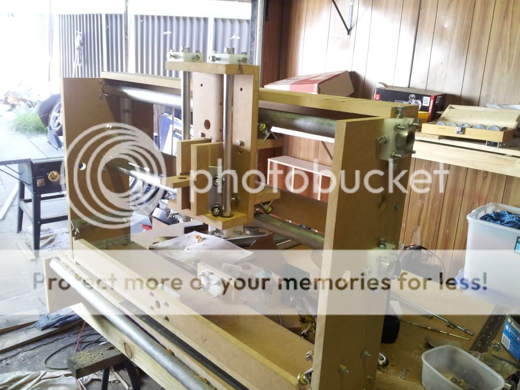
So here's a pic of the gantry, it is now on the base while I check a few things. Will get more pics tomorrow.
Cheers
-
03-08-2012, 02:03 AM #17
Registered
- Join Date
- Nov 2011
- Posts
- 211
Well, I actually finished this machine and fired it up on my SLAmsteppers. While it did cut out some letters for the kids, it was basically rubbish so it has now been pulled apart down to the table. I can still use that (although I did add a sheet of 18mm MDF on top) and redesign all the rest from various machine plans and threads on here.
My first task is to set up my tools to actually cut square and straight and to drill holes in the same place every time.
So this machine had a very short life but along the way it taught me heaps. The next machine will hopefully be more accurately built, i will just not hurry this time (was impatient and sick of building!).
Cheers
Bruce

 Reply With Quote
Similar Threads
-
Need some direction to build a small machine to allow me to build a larger one
By Dman65 in forum DIY CNC Router Table MachinesReplies: 3Last Post: 01-05-2013, 05:24 AM -
Mint's Build Aluminum/Steel Build thread.
By FreshMint in forum Maintenance DIY DiscussionReplies: 0Last Post: 10-31-2011, 04:18 AM -
Newbie - To build or not to build Router/Plasma Table
By dfranks in forum Waterjet General TopicsReplies: 10Last Post: 04-08-2011, 05:16 AM -
New Large Table Build in Houston, TX (Build Log)
By anitel in forum Plasma, EDM / Other similar machine Project LogReplies: 12Last Post: 12-30-2008, 09:45 AM
