


Needing a little reassurance on PWM speed control for a Hitachi X200 and a G540.
The way I read this I can connect:
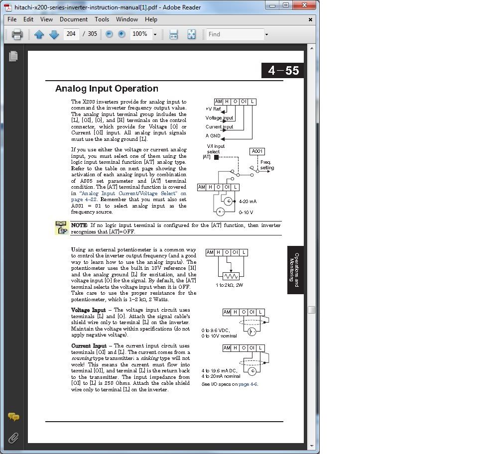
G540 pin7 (ground) to terminal L on the VFD (Analog Ground)
G540 Pin 8 (VFD Output) to terminal "O" on teh VFD (voltage Input)
G540 Pin9 (VFD +10VDC) to terminal H on the VFD (10V Referance)
set A001=01 (analog input as freq source)
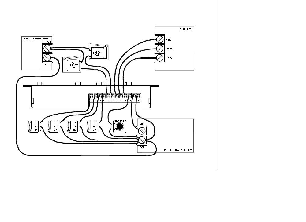
Plus I will use a G540 output and a relay to switch P24 and a programable input for Run.
Am I close??
Here are the diagrams.
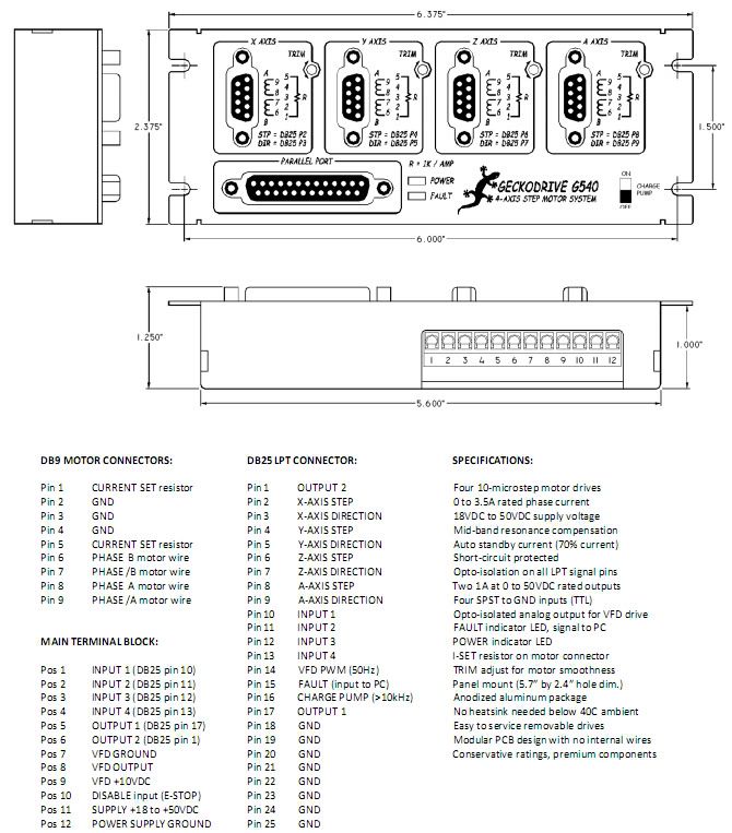
OUTPUTS: The G540 has two general purpose outputs called OUTPUT 1 and OUTPUT 2 on the MAIN TERMINAL BLOCK. They are at Pos 5 and Pos 6 respectively on the terminal block. These outputs may be used to drive relay coils or for any other purpose. The outputs are rated at 1A and 50VDC maximum. Connect one end of the load to the output and connect the other end of the load to a positive DC voltage. This voltage may be the G540 power supply or it may be a separate power supply having a different voltage.
ANALOG OUTPUT: This is a 0V to +10V opto-isolated analog output intended for use with VFD drives. VFD OUT goes to 0VDC while the G540 is disabled. Connect VFD GND, VFD OUT and VFD +10V to the VFD drive inputs. Make sure the VFD drive positive voltage does not exceed +12VDC. Do not short VFD OUT to any other terminal. Do not reverse polarity to VFD GND and VFD +10V or the G540 may be damaged
Please and Thank you
Mikie
Results 1 to 11 of 11
-
12-29-2011, 05:52 PM #1
 Registered
- Join Date
- Dec 2005
- Posts
- 58
Hitachi X200 to G540 - PWM speed control and run
-
12-16-2012, 01:51 AM #2
Registered
- Join Date
- Sep 2012
- Posts
- 108
can anyone confirm this is correct. I want to control my x200 fvd with gecko540/mach 3
-
12-18-2012, 02:22 AM #3
Gold Member


- Join Date
- Sep 2010
- Posts
- 1765
none
NO -- DO NOT WIRE ANYTHING TO ETHEIR OF THESE PINS - NOT NEEDED AND IT WILL SHORT OUT THE HITACHI INTERNAL AND G540 THINGS +10V SUPPLIES TOGETEHR.. G540 Pin9 (VFD +10VDC) to terminal H on the VFD (10V Referance) Originally Posted by BloomingtonMike

MIKE you are very close, yes. i assume g540 has some kind of output that can supply +24v or sink it so you should not need a relay in between for the run command. but I know nothing of this g540 thing.
-
12-18-2012, 03:06 AM #4
Community Moderator
- Join Date
- Dec 2003
- Posts
- 24221
It looks OK to me, the VFD +10v analogue supply is used to supply the Gecko isolated PWM to Analogue convertor, H,O, & L).
The relay Contact closure is used to switch P24 to the run input terminal.
Presumably BloomingtonMike got it right as that was a year ago!
Al.CNC, Mechatronics Integration and Custom Machine Design
“Logic will get you from A to B. Imagination will take you everywhere.”
Albert E.
-
01-14-2013, 05:26 AM #5
Registered
- Join Date
- Aug 2011
- Posts
- 73
Hi Mikie,
Were your 3 connections b/w G540 & Hitachi inverter correct in the end?
I have a WJ200 which is nearly identical and wanted to confirm before I power up.
Cheers,
Richard (Melbourne, Australia)
-
03-08-2018, 11:25 PM #6
Registered
- Join Date
- May 2013
- Posts
- 5
Re: Hitachi X200 to G540 - PWM speed control and run
I have a couple of questions. I have a copy of the wiring diagram above with the vfd drive wired to the G540. I have the two relays as shown, but I have no idea what the unit that is referred to in the diagram as Relay Power Supply is. Is it a relay, a power supply or what?. Also I have a KL 48v power supply in my G540 Control box ans a Separate vfd with its own power supply. Is it possible to run the inverter/vfd from the KL Power supply already in my G540 control box?
-
03-09-2018, 05:07 AM #7
Community Moderator
- Join Date
- Dec 2003
- Posts
- 24221
Re: Hitachi X200 to G540 - PWM speed control and run
What do you mean by 'run the inverter/VFD from the G540/KL?
What make of VFD?
In most cases you can eliminate the VFD Run relay, I have a separate post on it.
Al.
.CNC, Mechatronics Integration and Custom Machine Design
“Logic will get you from A to B. Imagination will take you everywhere.”
Albert E.
-
03-11-2018, 06:34 PM #8
Registered
- Join Date
- May 2013
- Posts
- 5
Re: Hitachi X200 to G540 - PWM speed control and run
. Originally Posted by lyjcncnuser
To clarify, by "KL", I was referring to the 48v power supply in my G540 controller box. It is actually a Mean Well NES-350-48 7.3 amp supply.
The VFD is a Dema:
Model: D5M-1.5S2-1A
Input voltage: Single-phase 220V/110V 50Hz
Power (KW): 1.5KW
Capacity of driver (KVA): 2.8
Output current (A): 7.0
Applicable motor (KW): 1.5
VFD is using a RS485 communication interface.
The VFD came with the Chinese 6040 CNC. As well as the VFD, the Chinese controller box also contained cheap stepper controllers. I bought the better G540, pre-wired in a controller box with a 48v power supply and E-Stop.
What I would like to do is move the VFD from the old controller box to the G540 controller box and run the G540 and the VFD using a single power supply .
My first question is "in the diagram the unit that is labelled "Relay Power Supply". Is it a relay or a power supply; or is it something else altogether"
Question 2 is can I move the VFD to my G540 controller box and just use a single power supply.
-
03-11-2018, 06:43 PM #9
Community Moderator
- Join Date
- Dec 2003
- Posts
- 24221
Re: Hitachi X200 to G540 - PWM speed control and run
You generally do not need any relay supply if using RS485 as all the control features are done via this method.
Al.CNC, Mechatronics Integration and Custom Machine Design
“Logic will get you from A to B. Imagination will take you everywhere.”
Albert E.
-
03-11-2018, 08:16 PM #10
Community Moderator
- Join Date
- Mar 2003
- Posts
- 35538
Re: Hitachi X200 to G540 - PWM speed control and run
The G540 runs from the 48V power supply.
The VFD needs 220V AC.
You may be able to power the 48v supply from the same AC as the VFD.Gerry
UCCNC 2017 Screenset
http://www.thecncwoodworker.com/2017.html
Mach3 2010 Screenset
http://www.thecncwoodworker.com/2010.html
JointCAM - CNC Dovetails & Box Joints
http://www.g-forcecnc.com/jointcam.html
(Note: The opinions expressed in this post are my own and are not necessarily those of CNCzone and its management)
-
03-13-2018, 07:03 PM #11
Registered
- Join Date
- May 2013
- Posts
- 5
Re: Hitachi X200 to G540 - PWM speed control and run
My VFD is 110v/220v switchable; I have it set up to run from 110v. Originally Posted by ger21
Also thanks to both you and Al_The_Man for your help.


 Reply With Quote
Similar Threads
-
HITACHI X200 settings
By 15mgtar in forum DIY CNC Router Table MachinesReplies: 99Last Post: 03-29-2015, 12:48 AM -
possible Problem with Hitachi x200 vfd
By jayty97 in forum DIY CNC Router Table MachinesReplies: 9Last Post: 09-18-2012, 08:08 PM -
Hitachi X200-022-NFU
By kolias in forum Open Source CNC Machine DesignsReplies: 0Last Post: 05-13-2012, 02:26 AM -
Hitachi X200 VFD Questoins
By crane550 in forum DIY CNC Router Table MachinesReplies: 1Last Post: 04-21-2012, 05:41 PM -
Hitachi X200?
By fritts in forum Phase ConvertersReplies: 2Last Post: 12-27-2008, 04:06 AM
