


Howdy, I'm sure this has been debated before, but I'm having a bit of trouble visualizing the ideal setup for my situation.
I'm designing and building a 3 axis CNC mill, making the frame out of Bosch extrusions, etc. It'll be a moving X, fixed gantry setup.
Anyway, here's my question. I want to be able to mill aluminum parts - I realize it won't be the most amazing mill out there considering my budget, skills, etc. But I do want to have a few inches of Z travel to I can work with pieces that aren't necessarily flat. The problem with most of the DIY systems I've seen is, the Z clearance is limited by the height of the Z axis carriage, not so much the total available travel. This probably doesn't make sense, so I'll try to paint a picture with words
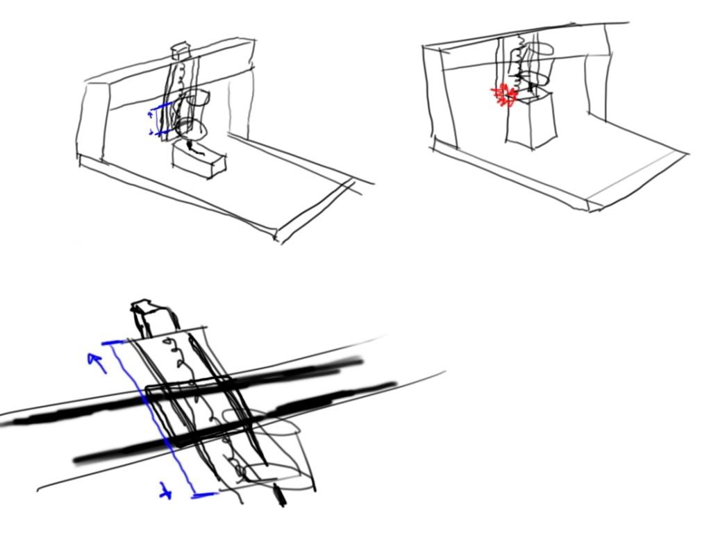
Let's say I build my gantry so that the lowest point on the Y axis carriage is 10" away from the table. Great. Now I add my Z axis and I have 2 options. I can mount the Z axis so that it's lowest point lines up with the lowest point on the Y axis carriage. That means I have lots of clearance, and I can move my work pieces up using blocks/raisers to meet the tool. But if I need to raise the tool more than a couple inches, the carriage itself with now be the lowest obstruction. Hard to explain what I mean, but I'll attach a picture that might help clarify.
Would it be possible/wise to do it the other way around? Instead of having a static (in Z) carriage/motor/rails assembly and a moving platform attached to the ballnut on the ballscrew that the tool is bolted to, could the ballnut and bearing blocks be attached to the Y axis (so they remain static in Z) and the whole rails/motor/screw/tool holder and tool move up and down? I realize it would add a lot of extra load to the ballscrew and rails, but wouldn't it add a lot of usable clearance?
Thanks in advance for any comments.. Sorry if my terminology is way off!
Results 1 to 6 of 6
-
01-12-2012, 12:30 AM #1
 Registered
- Join Date
- Jan 2012
- Posts
- 469
Z axis height and spindle mount offset
-
01-12-2012, 05:40 AM #2
Registered
- Join Date
- Jan 2008
- Posts
- 853
@tiagoSantos: Perhaps I misunderstand what you are suggesting, but what I think you are proposing is done quite frequently, Joes CNC 2006 is a very popular model with a vertical screw and stepper that are fixed in Z and a Z plate that moves vertically carrying the spindle. The thread is here
http://www.cnczone.com/forums/joes_c...006_a-145.html
In general the gantry clearance is designed such that it is near the limiting constraint, and the spindle can move up as far as necessary to machine at this level. Any other way has an excessively high gantry, and this leads to a loss of rigidity. Most folks go for ~6" working height or less; most could probably go with even less since many machines cut relatively thin stock.
Cheers!
-
01-12-2012, 06:36 AM #3
Gold Member
- Join Date
- Apr 2009
- Posts
- 5516
TiagoSantos, I built a machine based on Solsylva.com plans, which also has the rails and plate moving together. Then when I built my newer machine, I used the same principle.
There are some advavntages and disadvavntages to both, but I prefer to have the rails on the z plate. But to compare the two:
Gantry height: With moving rails, you would need more clearance under the gantry beam. With stationary rails, it would be lower. But now, to have the same amount of travel with the stationary rails requires either having the bearing blocks closer together than with moving rails, or making the carriage taller. Having the bearing blocks mounted fixed on the carriage, you can spread them the maximum amount. Plus I feel it is less complicated to make stiffer gantry legs than a stiffer carriage.
Ridgidity: Going back to the bearing blocks, the farther they are apart, the more ridgid your z axis will be. One factor, like PaulRownTree says, is if you have a minimal amount of z axis travel, then you could spread the bearing blocks farther apart without making a tall carriage. If you put those bearing blocks close together then your z plate will act as a lever against your gantry beam, and your router will be dangling at the bottom of the plate, regardless of the plates position on the z. You can reinforce the plate with bracing but at the end of the day it's still dangling.
Ease of fabrication: I think the stationary rail version is somewhat easier to fab. But here again, to have the same travel as a moving rail system, you have to make the carriage higher, and then usually the stepper/servo is placed on top, in not the best place weight wise, and magnifying any lever effect on the gantry. The moving rails also have issues as well. Either the drive motor is mounted on the same plate, making it heavier, or mounted on the carriage, making the design compact but then complicating things by necessitating use of timing belt and pulley, or designing a plate with clearance for the drive motor.
Depth of cut: By far, a moving rail system win hands down.
Other things to consider: You got to figure out what is the thickest piece you will be cutting. Your endmill will have to stick out at least that much and then some from the collet.You also want the cutter a safe jeight above teh work when rapiding. There's got to be another 1-1/2"-2" between the collet and spindle bottom. So how tall do you have to make the carriage, and how much overhang you'll have, and how and where you mount your spindle, will play a role in determining what you'll do.
-
01-12-2012, 07:08 AM #4
Registered
- Join Date
- Jan 2012
- Posts
- 469
Thanks Paul and Louie for your replies!
I should have known that these things have been around long enough that the chances of me having a new idea were next to none Good to know that it wasn't a silly idea.
I still haven't completely decided what the gantry height and travel will have to be for my needs. I'm a napkin sketch kinda guy, but I think most of my design is sort of figured out. Needless to say I'll be copying a lot of stuff I've seen here from other people. I think I will be going for the moving rails design, as the possibility of deeper cuts without ever being limited in X travel is important to me. I don't think I'll need more than 6" of travel, might even get away with less, as long as they're usable throughout the whole length of the X axis! I understand that the higher I make my gantry, the more trouble I'll have to make it rigid enough for my goals (the occasional aluminum part..).
Thanks again for your help, really appreciate the patience! I have my motors here, lots of parts coming in the mail, can't wait to start getting things together
-
01-13-2012, 05:42 PM #5
Registered
- Join Date
- Dec 2010
- Posts
- 634
I'll pass along another tidbit I learned here: as a general rule of thumb, you need your Z-axis travel to be at least equal to your gantry clearance plus the length of your longest bit.
E.g., Let's say your gantry clearance is 5", the end of your collet can drop down to 1" above your table and your longest bit extends 3" beyond your collet, you'll need to be able to retract 7" from the lowest z point to be able to fully clear a part that just fits under your gantry.
I have ~5.5" clearance under my gantry with ~8" Z axis and so far, I haven't had any problems retracting. My longest bit extends 4" beyond my collet and I've machined parts almost 4.5" above my table top.-Andy B.
http://www.birkonium.com CNC for Luthiers and Industry http://banduramaker.blogspot.com
-
01-14-2012, 04:05 AM #6
Gold Member
- Join Date
- Apr 2009
- Posts
- 5516
Well another thing to consider is that depending on your construction, it might be easier to make the gantry uprights stiffer, where you have a lot of room, rather than the carriage, where you don't. Also, like the solsylva, mechmate, momusm and other portal style machines, you can raise the rails on the x, and mount your bearing blocks to your gantry beam as well... Originally Posted by TiagoSantos


 Reply With Quote
Similar Threads
-
105mm spindle mount.
By blazedforever in forum DIY CNC Router Table MachinesReplies: 2Last Post: 10-19-2012, 04:05 PM -
Router Mount Height
By Jkountz in forum Open Source CNC Machine DesignsReplies: 1Last Post: 12-21-2011, 01:41 AM -
Spindle Mount Indicator
By behindpropeller in forum Haas MillsReplies: 0Last Post: 08-07-2009, 08:13 PM -
Height offset gage
By moniker in forum Calibration / MeasurementReplies: 0Last Post: 08-18-2006, 06:30 AM
