


Your machine is looking fantastic !!
We did a similar dual axis Z a few years back and it turned out great , we estimated it could lift at least 100lbs, with 270oz motors, and if I can remember correctly the screws were a 5TP
You should feel confident about your design it should have no issues lifting the Z gantry with two motors,
here’s some pics buried somewhere in these links
http://www.rockcliffmachine.com/forum/showthread.php?t=111
http://forum.canadianwoodworking.com/showthread.php?28369-Home-Made-Aluminum-CNC-Router
the customer on this machine did eventually use some counter weights, but only because the acme nuts were wearing a little more then normal
with the additional load weight,
I would not expect any issues with your ball screws
Your going to love the rotating nut there great, takes a bit more money and time but great,
Just have a question for you, on your rotating nut, did you have to center the nut in the bearing, I only ask because every rotating nut I have done in the past the center line of the ball screw has never been true to the flange, and I have always had to leave space to adjust the rotating center line?
Results 21 to 40 of 43
-
05-10-2012, 11:42 PM #21
 Gold Member
- Join Date
- Jan 2007
- Posts
- 175
Rockcliff Machine Inc.
http://www.rockcliffmachine.com
-
05-10-2012, 11:53 PM #22
Gold Member
- Join Date
- Apr 2009
- Posts
- 5516
Looking good!
-
05-11-2012, 01:17 AM #23
Registered
- Join Date
- Oct 2005
- Posts
- 612
Your build is coming along nicely.
Can you provide details and the supplier of the spindle - 50000rpm interests me.cheers,
Rod
Perth, Western Australia
-
05-11-2012, 05:16 PM #24
Registered
- Join Date
- Aug 2008
- Posts
- 409
Hey Rockcliff, Ive been following your CNC to 3D printer thread and the one on your forums for a bit now, I will probably be using one of your dual drive extruders on my machine if you guys decide to sell a kit, or i'll attempt to make one if time allows. Originally Posted by rockcliff

As for the rotating nut, I did a test run un-powered yesterday and it seems to glide smoothly, I didnt have to allow any adjustment to the centerline, the ball nut it centered in the collar and the collar is slipped into the bearing block. It seems to rotate just fine with no noticeable wobble or uncenteredness lol.
We'll see how it goes when its driven by the stepper and I get it up to full speed.
-
05-11-2012, 05:20 PM #25
Registered
- Join Date
- Aug 2008
- Posts
- 409
Thanks Louie! Originally Posted by louieatienza
Yes, the spindle is just the Keling/Automation Technologies Inc. KL-300 spindle, with the VFD300 drive 300W. Info can be found here: Originally Posted by Rodm1954
High-Torque Stepper Motor, Stepper Motor, Driver, Stepper Motor kit, DC Servo Motor, DC Servo Motor kit, Stepper Motor Power Supply, CNC Router, Spindle, and other Components. Automation Technology Inc
The info states that it can run from 10000-60000rpm, but from reading posts on here about it most people seem to run it at around 40-50000rpm.
I'll let you know what I think of it when I get a chance to test it.
-
05-12-2012, 02:18 AM #26
Registered
- Join Date
- Oct 2005
- Posts
- 612
Thanks for the spindle details - looks good.
cheers,
Rod
Perth, Western Australia
-
05-13-2012, 06:32 PM #27
Gold Member
- Join Date
- Jan 2007
- Posts
- 175
Yes, 3D printed parts are both functional and quite entertaining to do, the extruder is a great tool to have on your cnc router, I believe Fabiitrabbit is looking at some kit’s, but there are also some drawings we recently uploaded to make one yourself, which is a good project for the cnc. Originally Posted by Phife
On the subject of rotating nuts, I think the next one I make, I should plan it out a little better, it always seems to be an after thought, so I am probably not selecting the best components, or at least looking at the specs too closely.
As mentioned your cnc is looking great, and looks like it will be alive very soon, very nice.!Rockcliff Machine Inc.
http://www.rockcliffmachine.com
-
05-14-2012, 07:02 PM #28
Registered
- Join Date
- Aug 2008
- Posts
- 409
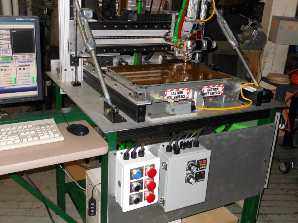
Some more progress pictures.
I had a large 1"thick aluminum plate that was just oxidizing away, I was originally going to get a new piece of aluminum for the table but since im already over budget I plan on just using this piece for now, Its only 28x28" so It will be a about 2" short in the long axis and about 8" too long in the short axis, but it should work just fine for now. It also has some holes along the edges that I should be able to live with. I plan on surfacing the plate with the spindle once its all up and running to make sure its flat and parallel to the spindle.
Feel free to ask questions, or comment on my machine, I love getting feedback as to what you guys think!
-
05-15-2012, 07:52 PM #29
Member
- Join Date
- Apr 2007
- Posts
- 1955
I am really glad to see your progress, especially since I am thinking similarly about the Z approach.
When it comes to final alignment, what are your plans to make it all square, etc ? At some point, a person has to pick an axis and declare it "good", then work from there I guess.
For example, I had doubts about my ability to align 4 each Z rails and keep it all going really vertical and free moving.
I guess one way to align is to start with the Z, and then move outward. The other is to get the table close, and pour self leveling epoxy on it, and use that as your "flat surface". The ideal approach isn't always obvious to me on the alignment aspect.
I haven't met anyone that doesn't like a rotating nut on the ball screw concept you are using and posts "I wish I had done something else". The whole ball screw thing is giving me budget challenges though.
Given the high value, are you planning to add some brushes to swish sawdust off of them ?
Thanks for posting your build info.
Harry
-
07-04-2012, 10:17 PM #30
Registered
- Join Date
- Aug 2008
- Posts
- 409
Update
Havent had a much time to work on the machine, im building it at work and work has been busy lately. I get an hour here and there, but its close to being complete.
Ive done all the electronics for the CNC, I have a few more parts to buy still for the 3D printer.
I'll do a breakdown of the parts, details, incase anyones interested.
Structure:
-6 Series extrusion for the frame from Misumi, Linear rails bolt right on and are pretty bang on straight, I have about 0.01" adjustment to get the rails aligned, I had to drill out the supported rail hole one size bigger or the M6 screws would not fit through.
-12mm Aluminum plate from Misumi, I had it most of it milled on 6 sides to ensure they were accurate in side and flatness, and I used my other CNC machine to center drill the holes on the faces, I then drilled them out manually on a drill press, I would have rather bored the holes with the CNC but my other CNC had some issues. Edge holes were sent to a machine shop to be drilled and tapped, I didnt trust my equipment to do it correctly.
-Brackets, Tslot Nuts (Pre-assembly and Post-assembly) from Misumi, Brackets were pretty decent price, nuts were a bit pricey, I guessed at how many I needed and ran out and had to order more.. I suggestion to anyone else drawing a machine like this in CAD, draw all the nuts and bolts so you have an accurate count. Sucks to run out. The post assembly drop in nuts were nice for when you forgot to put in a nut before assembly but they dont hold as strong as the pre-assembly nuts.
CNC Electronics
-Ethernet Smoothstepper
-Gecko G540
-Gecko Nema23 Steppers
-48V Powersupply from Keling
-DC Volt & Amp Meter
-G540 Cables from cncrouterparts w/ 3.5ohm resistor in moulded cables
-Nema23 Back Covers From CNC4PC
-C23 BOB fro CNC4PC for Smoothstepper
-RJ45 BOB for connecting to smoothstepper inside case
-12V 1A adapter
-Various Relays (for Start, VFD, and Coolant)
3D printer Electronics/Parts
-Gecko 251X for Extruder steppers
-Nema17 Steppers for Extruder
-Gnexlabs Temp controller for Extruder and Hotbed
-12V 30A powersupply
-5v 1A powersupply
-Jhead Hotend
-Custom 20x24 Silicone heater mat for hotbed
-MK6 Drivegears for Extruder
I think that covers most of it.. I expect to have the Engraver done in a week or so, and the 3D printing part in about a month. I have the VFD for the spindle connected to the G540 and im able to get it to turn on via Mach3, but for some reason the 0-10V input is not working and I only get full speed, Seems to be a problem somewhere either the Smoothstepper is not putting through the proper signal to control the G540s VFD output or theres some other issue with a Mach3 Setting or wiring.
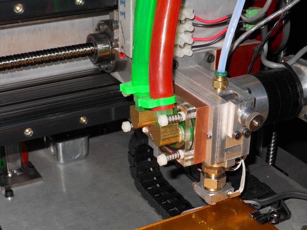
Heres some pictures of the progress.
-
07-04-2012, 10:22 PM #31
Registered
- Join Date
- Aug 2008
- Posts
- 409
I spent a while getting the frame as level and square as possible, then I worked on each linear module induvidually getting the rails straight and inline with eachother, Then mounted it all together and kept on measure to make sure I stayed as lined up as possible. I know its not 100% perfect but everything slides nicely and without binding, these types of bearings can take some misalignment and still run smoothly so Im not too worried about it, once I have the table on and I can actually machine something I'll surface the table and check everything for tram with my DTI. Originally Posted by harryn
The ballscrews were pretty cheap, most are well out of the way and only the table screw is exposed, I will use some sort of way cover when I get the table done.
Rotating nut works great! im very pleased with its outcome, I can get 400ipm rapids so far, im going to tune the G540 and play around with the mach3 setting when I get everything done so see how much more I can push it
-
07-05-2012, 12:04 PM #32
Member
- Join Date
- Dec 2007
- Posts
- 2134
What a great build! That's a terrific looking machine!
cheers,
IanIt's rumoured that everytime someone buys a TB6560 based board, an engineer cries!
-
07-07-2012, 04:13 PM #33
Registered
- Join Date
- May 2007
- Posts
- 122
Nice design. It is good to see something other that MDF or the usual shaped machines on here. I am looking foward to seeing it finished.
-
01-09-2013, 08:38 AM #34
Registered
- Join Date
- Feb 2004
- Posts
- 138
Any update??
-
01-10-2013, 04:50 AM #35
Registered
- Join Date
- Aug 2008
- Posts
- 409
Ya, sorry.. Machine was finished except for the 3D Printer side. I milled a bunch of aluminum and engraved a bunch of stainless steel plates with it and had most of the electronics for the 3D Printer complete, I was waiting on an extruder from Qu-bd but I lost my job and since my old boss was paying for the machine and it was at his shop I never finished it. I ended up taking a bunch of electronics and parts that belonged to me off the machine so as far as I know it sits unused and unfinished.
Its a real shame, it would have been a great CNC/3D Printer. I may try to buy it off of him in the future but I just dont need it. Im working on a new 3D printer that will be similar to the DLP/Photo sensitive Resin based printers but with a much larger build area (16x12x12"). Im using an LCD panel instead of the DLP projectors.
Do a search for DLP 3D printers to see some of what they can do, I hope to start a campaign similar to the B9 Creator or the Formlabs Form1 in the future.
-
01-10-2013, 05:58 PM #36
Registered
- Join Date
- Feb 2004
- Posts
- 138
Bummers on the job loss, seems to be a lot of that going around. Hope all works out for you on the next machine. I sure liked that rotating ABL nut you designed and will doing some machine work on my own design of something similar soon. That was the main reason I was following your thread here. I have a running DIY 4'x4' CastCnc, mill #2, CastCNC - Home , acme screw drive system that I'll be making the rotating ABL nuts for. Right now I'm redoing my power box and adding a 4th axis drive to it.
AL
-
01-14-2013, 08:17 PM #37
Registered
- Join Date
- Nov 2010
- Posts
- 0
Yeah sorry you aren't able to work on this machine anymore, it was looking great! I was wondering if you remember where you got those enclosures you are using for your electronics? Those look just about perfect for what I need and I'm not having any luck finding them.
AM
-
05-03-2013, 02:09 AM #38
Registered
- Join Date
- Apr 2013
- Posts
- 97
Yours looked real good this is mine
I am laid off now to it belongs to me it is still at work i have to get it out

-
05-03-2013, 06:24 AM #39
Registered
- Join Date
- Nov 2006
- Posts
- 1036
Looks fantastic!!!!!!!!!!!! Have you made any videos?
-
05-03-2013, 02:40 PM #40
Registered
- Join Date
- Apr 2013
- Posts
- 97
Two poor quality videos

 Reply With Quote


Similar Threads
-
Fixed gantry vs moving gantry
By scott0999 in forum DIY CNC Router Table MachinesReplies: 11Last Post: 01-31-2014, 06:14 AM -
Fixed Gantry - Trying again
By harryn in forum CNC Wood Router Project LogReplies: 64Last Post: 04-08-2013, 02:51 AM -
Phife's First Build. Gantry CNC.
By Phife in forum DIY CNC Router Table MachinesReplies: 26Last Post: 01-21-2010, 08:19 PM -
fixed gantry
By eloid in forum DIY CNC Router Table MachinesReplies: 2Last Post: 01-29-2009, 11:20 PM -
Fixed Gantry
By Auzze in forum DIY CNC Router Table MachinesReplies: 1Last Post: 07-25-2004, 08:34 AM
