


Sure I have but I don't understand ASM.Originally Posted by Al_The_Man

Results 21 to 26 of 26
-
02-23-2012, 06:27 PM #21
 Registered
- Join Date
- May 2007
- Posts
- 35
-
02-23-2012, 06:31 PM #22
Community Moderator
- Join Date
- Dec 2003
- Posts
- 24223
There is only 35 instructions and the 16F628 manual explains them all. Originally Posted by DigiSoft
The free MPLAB S/W also has user manuals & guide.
Al.CNC, Mechatronics Integration and Custom Machine Design
“Logic will get you from A to B. Imagination will take you everywhere.”
Albert E.
-
02-24-2012, 04:38 PM #23
Registered
- Join Date
- Oct 2005
- Posts
- 2392
Hi again, I will explain the operation in simple terms.
The PIC generates analogue voltage steps, to give 6th microstepping (1200 usteps/rev).
This is done by setting the PIC pins HI or LO, which goes through the diodes and resistors and makes a fixed analogue voltage at the bases of Q1/Q2, and another separate analogue voltage at the bases of Q3/Q4. These are two independent "DACs".
Then the small transistors Q5,6,7,8 are used as "killers" which always hold two of the output transistors off.
So the combined effect is 2 independent analogue voltages (one voltage for each motor phase) and always two of the main transistors on (which gives 4 combinations, ie 4 "fullsteps" in total).
The main transistors are driven linear, by analogue voltages, so there is no PWM needed, and the current through the stepper motor coils is constant and smooth.
However to get 18th usteps (3600 usteps/rev) the Lini can PWM its outputs to produce more usteps between the hardware usteps. However this still makes a constant analogue voltage at the bases because the PWM is filtered by the DACs and C5/C6 to make a constant DC voltage.
People's attempts to simulate the Lini don't work well because simulators are just not very good. If you want to get the very smooth linear current ramps as shown here;
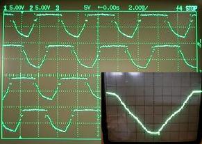
that naturally occurs at the right speed, as the Lini is "tuned" using caps C5/C6 to be very smooth during a particular RPM range, where resonance often occurs.
-
07-01-2013, 01:30 PM #24
Registered
- Join Date
- Dec 2010
- Posts
- 7
Thanks Roman, Originally Posted by RomanLini
Your explanation in 'simple terms' enriched me, I assumed that 18th microstep positions are achieved by fast changing between these DAC output in right proportion in the software. But I still cannot understand why D3 and D6 is used in reverse direction with respect to D1, D2 and D4, D5 respectively, where D1, D2 and D4, D5 blocks 'back flowing' in the DACs.
Many many thanks again for the above post.
p55xp
-
07-01-2013, 02:46 PM #25
Member
- Join Date
- Mar 2009
- Posts
- 533
D3 and D6 ensure that the controlled discharge pathway is separate or independent from the charging pathway, of C5 and C6. Hence their reverse polarity when compared to the other diodes.
-
07-01-2013, 06:40 PM #26
Registered
- Join Date
- Dec 2010
- Posts
- 7
Thanks a lot KOC62 for your prompt response. Now I must try again to evaluate the hardware in context of PIC code, and write again if face any problem.
p55xp

 Reply With Quote
Similar Threads
-
Question about Linistepper v2
By tomovsb in forum Open Source Controller BoardsReplies: 33Last Post: 07-24-2017, 10:38 PM -
Linistepper in C
By hazimin in forum PIC Programing / DesignReplies: 9Last Post: 01-24-2011, 03:34 AM -
Quick Schematic Question
By Cartierusm in forum PIC Programing / DesignReplies: 6Last Post: 01-18-2009, 12:06 AM -
Linistepper
By tante in forum Open Source Controller BoardsReplies: 7Last Post: 12-19-2005, 04:24 PM -
CNC router wiring schematic question.
By CRFultz in forum CNC Machine Related ElectronicsReplies: 3Last Post: 11-26-2004, 06:22 PM
