


i purchase a 5 axis board of ebay to setup with my geckodrive G201x but not sure how to setup the input up.
need help please i'll also upload the files that came with it... please i need help:drowning:
Results 1 to 17 of 17
-
02-27-2012, 05:01 AM #1
 Registered

- Join Date
- Sep 2011
- Posts
- 0
5 axis breakout board wiring PLease :'(
-
02-27-2012, 05:02 AM #2
Registered
- Join Date
- Sep 2011
- Posts
- 0
this is the link to the board
eBay - New & used electronics, cars, apparel, collectibles, sporting goods & more at low prices
-
02-28-2012, 03:01 PM #3
Registered
- Join Date
- Jun 2011
- Posts
- 0
i wonder how that cheap breakout board handle your drive compare with other BOB.. Originally Posted by isowe

-
02-28-2012, 05:46 PM #4
Registered
- Join Date
- Sep 2011
- Posts
- 0
trying to find a good BOB right now, but i'm looking forward towards buying the pdmx-126 but i was unable to find a good wiring diagram. so I'll have to wait :violin:
-
02-28-2012, 07:06 PM #5
Member
- Join Date
- Mar 2009
- Posts
- 533
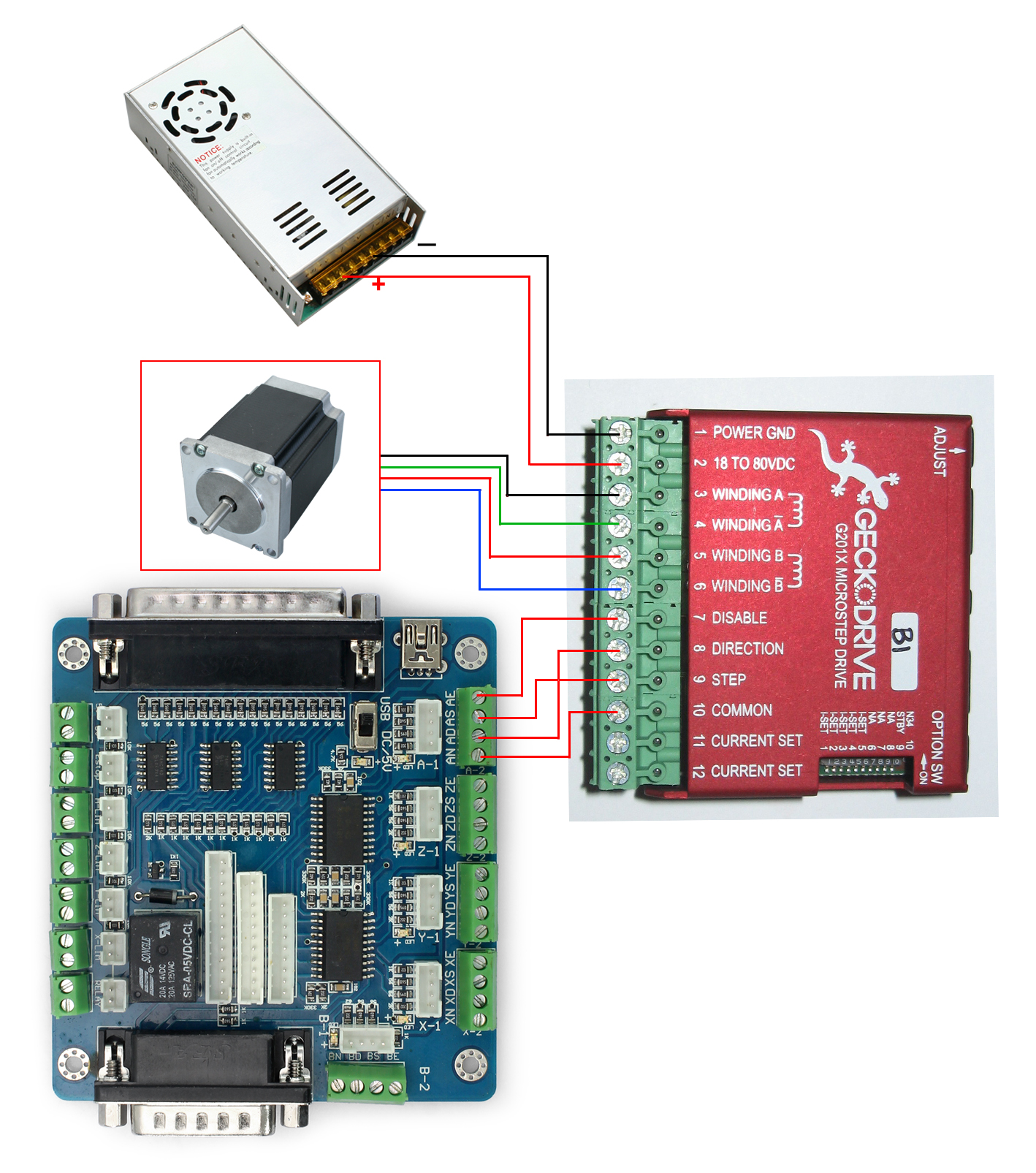
You need to get the manual for the G201.
Then use the GND, DIR, STEP, ENable to the similar inputs.
Take one axis, say "Y".
5-AXIS BOB G201
YN --------------- Power GND
YD --------------- DIR
YS --------------- STEP
YE --------------- DISABLE
The other axes will be similar.
What is not clear to me is whether the pulse direction is standardized. i.e. is YE high for enable? Is G201 DISABLE high or low for disable?
You will need to know the pulse direction for each device.
I don't have your devices so I'm only going by the data you provided and the G201 manual.
-
02-28-2012, 07:49 PM #6
Registered
- Join Date
- Sep 2011
- Posts
- 0
the ebay seller sent me this info,and it worked but the motors speed was slow. so i'm searching for a good BOB for the geckodrive. thanks for the help

-
02-28-2012, 08:10 PM #7
Registered
- Join Date
- Mar 2007
- Posts
- 2083
Hi isowe ,
as far as I can see , the minimum connections you need are
connect the G201's terminal 10 to the BOB's Ground
and the BOB's step and direction outputs to the G201's inputs
the breakout ENABLE outputs are via 1K resistor you will need to test
to see if this will correctly disable the G201 driver
John
-
02-28-2012, 08:19 PM #8
Registered
- Join Date
- Sep 2011
- Posts
- 0
i'll give it a try today and i'll also post a youtube video if i get the chance
") wish me luck
wish me luck
-
02-28-2012, 09:32 PM #9
Gold Member
- Join Date
- Jan 2010
- Posts
- 2141
Also note that the G201X can accept either a positive voltage or ground connected to the COMMON terminal (your diagram shows a ground connection) - the choice would depend on your Mach3 configuration (Low Active) settings.
-
12-16-2012, 01:11 AM #10
Registered
- Join Date
- Oct 2012
- Posts
- 9
do you know what the pins are for mach3? I have the same breakout board, I ordered it off ebay to see how good the board and driver kit was. Right now its a nightmare trying to figure out how to make it run! If I can't get this thing to work I'm just going end up purchasing a c10 breakout board from cnc4pc its the easiest board that I have worked with so far.
Heres the link if anyone needs a good board CNC4PC
-
12-16-2012, 03:01 AM #11
Registered
- Join Date
- Jan 2005
- Posts
- 1943
The pin definitions for the Chinese BOB are in the pdf manual in post #1 of this thread. Originally Posted by apsara
I have had that same chinese 5 axis BOB on both of my machines and have not had any problems at all. I know the C10 is popular and I am sure it is a good BOB, but I can't see how it can be easier than any other. This one seemed very easy to me.
-
12-16-2012, 12:53 PM #12
Registered
- Join Date
- Oct 2012
- Posts
- 9
its still not working for me.
is the board supposed to be buzzing loudly?
-
12-16-2012, 04:11 PM #13
Gold Member
- Join Date
- Jan 2010
- Posts
- 2141
Uh, no. Originally Posted by apsara
Could it be the relay (the large, black, rectangular object in the lower left in the board photo above) that is making the noise? If you put your finger on the relay, do you feel vibration coming from it?
-
12-16-2012, 05:08 PM #14
Registered
- Join Date
- Jan 2005
- Posts
- 1943
Thats a good thought. if you have the pin assignments wrong you could be sending a step signal to the relay causing it to rapidly latch and unlatch
-
12-17-2012, 02:10 AM #15
Registered
- Join Date
- Oct 2012
- Posts
- 9
I have never worked with this board before so don't really know what Im doing with it. I'll snap some pics of the setup and show you guys. I want to at least try and get this board to work before giving up and purchasing the C10. Another thing, mach3 doesn't seem to be working as well lol, wth. I installed it on to a new system, its running on vista. When I try and move the x,y,z axis with the arrow keys there is no movement in the coord's. It's works fine on my laptop but doesn't work on my desktop, what would cause that not to work?
-
08-18-2017, 03:25 PM #16
Registered
- Join Date
- Aug 2010
- Posts
- 2
Gecko drive - input open-colect?
http://www.cncitalia.net/forum/viewtopic.php?f=8&t=69471
-
08-18-2017, 08:13 PM #17
Registered
- Join Date
- Mar 2007
- Posts
- 2083
Re: 5 axis breakout board wiring PLease :'(
it depends on which Gecko Drive your talking about
the G540 opto-isolated inputs have the LED and 200 ohm resistor connected to a +12V DC supply
so you need to connect the G540's input to either a open collector output or one that is compatable with 12V logic levels
other Gecko drivers like the GM215 have the opto-isolator LED connected to ground and need to be connected to an output that can pull the input terminal up to +5V
John

 Reply With Quote
Similar Threads
-
CNC4PC.com C11 Breakout Board wiring.
By thunderdork in forum CNC Machine Related ElectronicsReplies: 1Last Post: 10-29-2013, 06:53 PM -
Breakout board wiring help!
By frostyshoal in forum DIY CNC Router Table MachinesReplies: 1Last Post: 05-08-2013, 03:05 AM -
Single Axis TB6560 driver and breakout board wiring
By badboy in forum Stepper Motors / DrivesReplies: 5Last Post: 07-10-2012, 11:26 PM -
wiring Chinese Breakout board
By silyavski in forum CNC Machine Related ElectronicsReplies: 7Last Post: 07-29-2011, 02:22 PM
