


I have been wanting to do this for a while. Having seen what others such as Hoss and Don have done I figure it's time to get started.
I've managed to collect most everything I will need to at least get started.
List of what I have:
Mni Mill
Ballscrew
3 Ball nuts
Bearings
Metal for mounts
G540 and 4 318oz/in steppers
Dedicated computer running Mach3 (dual boots w/ Linux to try EMC2 later)
Things I still need includesuggestions welcome)
Wire for steppers and sensors
Limit switches
Couplings
Anything else?
The plan is to get the 3 axis under CNC control, then enclose it. Future plans include setting up the spindle to be controlled by Mach3 as well as coolant.
Thread: Another LMS Mini Mill 3960
Results 1 to 19 of 19
-
04-22-2012, 06:36 PM #1
 Registered
- Join Date
- Apr 2005
- Posts
- 39
Another LMS Mini Mill 3960
-
04-22-2012, 10:44 PM #2
Member
- Join Date
- Apr 2006
- Posts
- 8159
http://www.hossmachine.info - Gosh, you've... really got some nice toys here. - Roy Batty -- http://www.g0704.com - http://www.bf20.com - http://www.g0602.com
-
04-22-2012, 10:52 PM #3
Registered
- Join Date
- Apr 2005
- Posts
- 39
Thanks Hoss, that's a great site.
Is there any reason that no one has run the Z axis ballscrew through the collumn othe than the machine work necesary to the column itself? I need to get to tearing the mill apart.
-
04-22-2012, 10:58 PM #4
Member
- Join Date
- Apr 2006
- Posts
- 8159
Now that I read what you wrote.

The column on the X2 isn't the biggest or thickest walled in the world so opening up a slot so its like a g0704 or rf45 would no doubt
weaken it a bit.
Still could be doable if you added some extra support on the rear like just about every other x2 conversion.
Hosshttp://www.hossmachine.info - Gosh, you've... really got some nice toys here. - Roy Batty -- http://www.g0704.com - http://www.bf20.com - http://www.g0602.com
-
04-22-2012, 11:29 PM #5
Member
- Join Date
- Apr 2006
- Posts
- 8159
However, cutting a long slot between the dovetails would likely cause flex inward between the dovetails since
there isn't a lot of meat in the column walls.
Hosshttp://www.hossmachine.info - Gosh, you've... really got some nice toys here. - Roy Batty -- http://www.g0704.com - http://www.bf20.com - http://www.g0602.com
-
04-22-2012, 11:49 PM #6
Registered
- Join Date
- Dec 2006
- Posts
- 839
You can run the screw down the back and bring support around both sides of the collumn to hook to the sides of the head. This would give equal pull on both sides of the head to keep from twisting it.
I am running the screw through the head on a X1. I see no problems with it as long as there is room and the head doesnt get weakened from the mod.
I would not cut the collumn any if I could get around it. No use in making a weak part any weaker.
JessGOD Bless, and prayers for all.
-
06-13-2012, 12:53 PM #7
Registered
- Join Date
- Apr 2005
- Posts
- 39
Well, I've been very busy working lately and have had no time to work on this myself. So I decided just to go with CNCFusions mechanical kit. I must say that the turn around time was faster than expected. I am looking forward to assembling everything and getting her moving under her own power. With a little luck I might have some time come Sunday to do it.
-
06-17-2012, 06:53 PM #8
Registered
- Join Date
- Apr 2005
- Posts
- 39
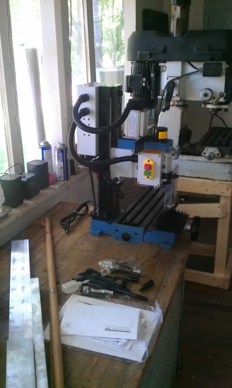
Well with work keeping me busy I didn't have time to fabricate my own conversion for the mill. So I ordered CNC Fusions kit. I have the mechanical done (other than two bolts) and I'll work on the electronics this evening.
Picture of the kit.

The mill done.

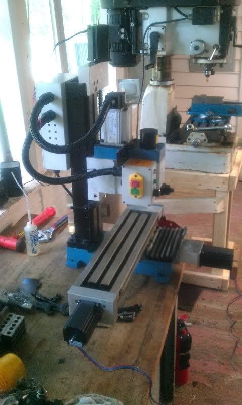
It was fairly straight forward using these instructions although there are a few places you have to have a little sense to complete the steps. CNC Mini Mill Conversion Kit (Hardware)
Also the Z axis bolts that must have there holes drilled in the column where not long enough to go through and use the nuts. Of course those are the bolts I don't have on hand so I will pick up a couple at the hardware store.
-
06-18-2012, 01:36 AM #9
Registered
- Join Date
- Apr 2005
- Posts
- 39
Ok, I got the wireing connected and just when I thought I was good to go...I do not have the correct parrelel cable. So I will order one along with some wire loom to make it look good. Maybe by next Friday I'll be moving under power.
-
06-23-2012, 07:23 PM #10
Registered
- Join Date
- Apr 2005
- Posts
- 39
Well I managed to finish up the miscellaneous nuts and bolts. She is mechanically sound.
I also connected the electronics and started configuring. Using the G540 XML file all I had to do was reduce the steps per rev to 10000 to match the .200" pitch on the Thompson ball screws that came with the CNC Fusion kit. I did have one bad solder connection to fix on the X axis DB9 connector.
Using a DI I now have the axis moving like they should. Now to get the CAD/CAM side configured.
-
05-24-2014, 02:19 AM #11
Registered
- Join Date
- Aug 2010
- Posts
- 3
Re: Another LMS Mini Mill 3960
Update? I'm going to get the 3990 LMS mill for some of the small fittings we machine. I can't stand using the large Haas for small stuff. How did everything work out for you?
-
09-04-2015, 10:29 PM #12
Registered
- Join Date
- Apr 2005
- Posts
- 39
Re: Another LMS Mini Mill 3960
Sorry for the late reply. I am just now getting into spindle control. I will be using the LMS board I just received. I will update this once I get it installed. The mill works fine for what it is. I basically see it as an educational experience. I would love to have a machine the size of a G0704 or even a Tormach... wouldn't everyone. I have been much more productive since I started using Fusion360 for CAD and CAM.
-
09-06-2015, 08:23 AM #13
Registered
- Join Date
- Aug 2015
- Posts
- 8
Re: Another LMS Mini Mill 3960
I have a LMS 3990 that I am converting. Just finished getting the Spindle control 90% working, Minus the Reverse function. I'm using a XHC-MK3 motion card and was unable to use just the LMS Spindle control board. This was because the LMS controller only accepts 0V-5V analog input for controlling the spindle speed and add the problem that in order for the Start circuit to function it must be sent to ground. To remedy this I simply added a Digispeed DC-03 V3 from PWM to analog controller between my motion card and the LMS Controller, this got the spindle speed functioning. To get the Start circuit operational I wasn't able to use the relays on the Digispeed due to not having access to both coil terminals of each relay (I am Assuming they share the devices ground). So I used another 5V relay with Start connecting to NO and GND from the LMS controller connecting to COM. On the relay coil terminals I connected a 5V PS by connecting Neg to 0V on the motion card, +5V to one coil terminal and the other terminal to Output#1. Then Output#1 is utilized as the CW relay in spindle settings.
Once the spindle is turned on:
PWM signal sent to digispeed converted to 0V-5V analog signal and sent to the LMS Controller which governs Speed
Output#1 goes into active high and activates the 5V relay and grounds the start circuit on the LMS controller
Spindle starts, speeds up, slows down, stops via Mach3 commands.
The next problems to tackle is enabling reverse rotation which I believe is gonna take another 3 5V relays to accomplish since in order to activate reverse rotation the start circuit must remain grounded and the M4 command currently cancels output#1 before it will activate output#2 so I'm gonna need 2 extra relays wired parallel to carry the start circuit when the reverse circuit is activated.
And then there is the problem with tachometer feedback to mach3. Once this can be established then we can calibrate the PWM to spindle RPM.
Right now I'm researching the tach problem while I wait for parts to arrive to finish the reverse curcuit.
-
09-06-2015, 12:00 PM #14
Member
- Join Date
- Feb 2008
- Posts
- 521
Re: Another LMS Mini Mill 3960
Why do you want reverse rotation? The only need I can fathom is for rigid tapping - how much do you plan to do?
-
09-06-2015, 07:27 PM #15
Registered
- Join Date
- Aug 2015
- Posts
- 8
Re: Another LMS Mini Mill 3960
As of now I don't know of a reason to need it, but I don't want to run into an issue where I end up needing it and have to wait till I've wired it up in order to use it. it's more of a (better to have it and not use it, than to need it and not have it) situation.
-
09-06-2015, 10:47 PM #16
Registered
- Join Date
- Apr 2005
- Posts
- 39
Re: Another LMS Mini Mill 3960
I managed to get the board installed and running. The only issues I've encountered are M5 allows the spindle to spin clockwise (looking dosn on spindle) very slowly. M3 spins the spindle CCW. M4 spins the Spindle CW. I've tried changing the outputs to active low and back. Below are pictures of my configuration.


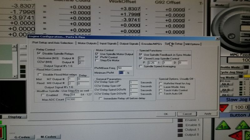
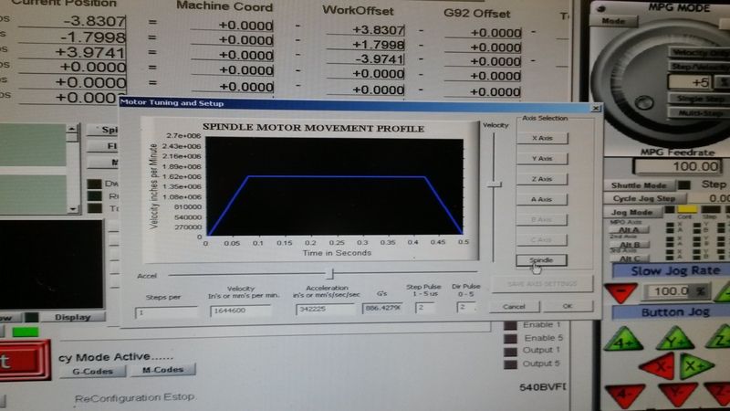
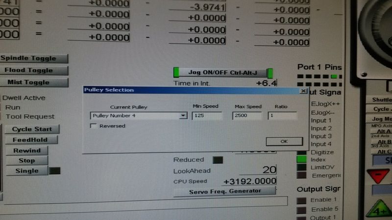
I belive I need to change the spindle min speed to 0. Perhaps then M5 will result in a full stop.
-
09-10-2015, 12:54 AM #17
Registered
- Join Date
- Apr 2005
- Posts
- 39
Re: Another LMS Mini Mill 3960
I belive I found my rotation direction problem. Under spindle control I should have the M3 and M4 outputs set to the same output. I will find out this weekend.
-
09-12-2015, 12:12 PM #18
Registered
- Join Date
- Aug 2015
- Posts
- 8
Re: Another LMS Mini Mill 3960
This is why I used the hardware I mentioned above. there are three circuits you need to control.. which are (Start, CW, CCW). as of now you are only controlling CW and CCW and start is remaining on all the time. and this needs to be controlled by a relay, it's not controlled by 0-10v. On the LMS controller if you downloaded the datasheet you'll see that start goes directly to ground to enable. but my situation may be different due to me having a USB motion card. I'm using a pair of relays wired together to create an (ElseIf situation) "Programmer lingo" to control all three circuits, I'm waiting on a voltage regulator to arrive in the mail later today to finish the addon card I built and test it, if it works I'll make a schematic of it and attach it here. Basically if relay1 is active it turns CW, if relay2 is active is turns CCW and if both are inactive, the Start circuit is cut off stopping the spindle completely and speed is controlled using the PWM to Analog controller. But once again, thats' my setup.
-
09-14-2015, 06:18 AM #19
Registered
- Join Date
- Aug 2015
- Posts
- 8
Re: Another LMS Mini Mill 3960
I've completed my simple relay board and now can successfully control FWD,Rev and comes to a complete stop (no slow unsteady rotation). Here is a copy of the interface board I made to handle it. all you need a breadboard, 2 relays, 2 LED's, 2 330ohm resisters. the relays I used were (JQC-3F) 5V 10A 125V 5 pin relays. I've got future plans to add in a 5v regulator so I can use my 24V P.S. rather then have a dedicated 5V P.S. for this board. This would allow the board to be powered with anything from 5V-24V.

 Reply With Quote


Similar Threads
-
Super Mini Mill 2 vs Mini Mill Tool Tracking
By Terry G in forum Haas MillsReplies: 0Last Post: 05-25-2014, 06:55 AM -
Should I buy Grizzly's new G0758 mill or LMS HiTorque 3960 mill ?
By rkovvur in forum Benchtop MachinesReplies: 6Last Post: 03-27-2014, 11:41 PM -
Drillbit test with mill LMS 3960 mill conversion
By msimpson99 in forum Benchtop MachinesReplies: 2Last Post: 10-20-2013, 11:20 AM -
LMS 3960 HiTorque Mini Mill
By cdavids in forum Benchtop MachinesReplies: 4Last Post: 08-29-2012, 01:45 PM
