


I'm working on a retrofit of a Tree vertical mill. Full thread here: http://www.cnczone.com/forums/vertic..._retrofit.html
I'm using Mesa 5i20, 7i37TA, and 7i48. AMC drives in torque (current) mode.
I haven't done any PID tuning other than increasing P to 60 in order to get the motors to turn at all. I'd like to use halscope to tune like this: LinuxCNC Documentation Wiki: PWM Servo Amplifiers
When I open halscope I can't find any of the signals he is using (ppmc.0.encoder.00.position,pid.0.command,pid.0.er ror,ppmc.0.encoder.00.delta) PPMC is Pico specific I imagine. I would like to be able to see the error between the commanded position and the actual position in halscope.
Thanks.
Thread: Halscope servo tuning PID
Results 1 to 20 of 31
-
05-09-2012, 05:07 PM #1
 Registered
- Join Date
- Apr 2007
- Posts
- 521
Halscope servo tuning PID
-
05-10-2012, 12:57 AM #2
Registered
- Join Date
- Feb 2008
- Posts
- 644
The pid.0.command and pid.0.error would be the same though I'm not sure if pid.0.command can be read so I would use emcmot.00.pos-cmd instead for commanded position. Originally Posted by will gilmore

hm2_5i20.0.encoder.00.position would be the actual (axis 0) position
-
05-10-2012, 03:28 PM #3
Registered
- Join Date
- Apr 2007
- Posts
- 521
Thanks.
I think its working using pid.x.error, hm2_5i20.0.encoder.00.position, and pid.x.command
I couldnt find any pins starting with emcmot.
-
05-23-2012, 04:39 PM #4
Registered
- Join Date
- Apr 2007
- Posts
- 521
I'm starting to tune.
Every time I need to change the ini file I close linuxcnc and halscope, reopen linuxcnc, reopen halscope, open the halscope config and rehome the machine.
Is there a way to have linuxcnc re-read the ini file without restarting?
-
05-23-2012, 04:46 PM #5
Registered
- Join Date
- Jul 2003
- Posts
- 1754
For tuning - you can use the 'Calibration' menu item under 'machine'.
This allows you to set the tuning parameters (PIDFF0-2) without restarting. (that is what I used to tune my machine)
sam
-
05-23-2012, 04:52 PM #6
Registered
- Join Date
- Apr 2007
- Posts
- 521
Awesome. Thanks
-
05-23-2012, 09:21 PM #7
Registered
- Join Date
- Apr 2007
- Posts
- 521
After tuning for a little while I'm realizing that the max acceleration for the axis plays a big roll in this. What is a reasonable acceleration for a biggish (48"x10.625" table) vertical mill? Right now I'm using 20"/s/s and I'm having trouble getting the initial error spike down. Its also my first time tuning servos so that could have something to do with it.
-
05-25-2012, 04:54 AM #8
Registered
- Join Date
- Mar 2004
- Posts
- 369
Well, of course. This page was written for the Pico Systems interface boards, not Originally Posted by will gilmore
the Mesa boards. So, the signal names will be different. However, you can scan the list
of available signals to find what you need. Mesa doesn't have "delta" but they should have
a velocity signal. The following error is the same, it is from the PID component, and is
not hardware specific. So, that would be pid.0.error
If you don't have a pid.0.error, then the whole config must be really wrong.
This is not a signal, it is a pin, maybe that's why you can't find it. It should be attached
to a signal in the hal file, but you should be able to find it in the list of pins.
Really, velocity and pic.0.error are the only pins you need to look at. velocity is good to
trigger the scope trace from and identify the portions of the move (accel, cruise, decel),
and the error is all you usually need to look at.
Jon
-
05-25-2012, 04:30 PM #9
Registered
- Join Date
- Apr 2007
- Posts
- 521
Hi Jon, Thanks for the reply. I've been tuning using pid.0.error, pid.x.command, and h2m_5i20.0.encoder.00.position. I'll try looking for a velocity pin.
While I have your attention, what max_acceleration are you running? You are running a bridgeport IIRC.
-
05-25-2012, 11:15 PM #10
Registered
- Join Date
- Feb 2008
- Posts
- 644
Note that you can tune out some of the error during acceleration with a small amount of FF2, just as you can tune out the error during a constant velocity slew with FF1 (assuming velocity mode dives here) Originally Posted by will gilmore
-
05-26-2012, 04:05 AM #11
Registered
- Join Date
- Mar 2004
- Posts
- 369
Hmmm, strange, I answered this this morning, but it never showed up. I have really Originally Posted by will gilmore
wimpy motors on that machine, 1/8 Hp continuous, and 3/8" wide XL belts. Whenever I turn
up the acceleration, it breaks a belt within 5 minutes. So I have the accel set to 3 inch/second^2.
This can cause some rounding of corners.
If your motors are more powerful and your mechanicals stronger, you should be able to set it
quite a bit higher.
Jon
-
05-27-2012, 05:17 PM #12
Registered
- Join Date
- Apr 2007
- Posts
- 521
PCW - I'm using my drives in torque (current) mode but I have been experimenting with FF1 and FF2 and I have had some success getting it to do what you say.
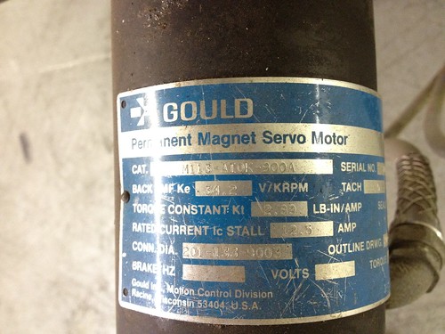
Jon - This is the motor 12.5A
and this is the mil roughly 10"x50" table
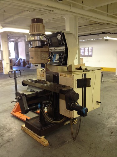
I'm not at the machine right now but the ballscrews are .2" and there is some reduction between the servos and the ballscrew (encoder is at the screw so I didn't look that closely. It's probably 3ish:1). What kind of acceleration should this be able to achieve? It seems like if I have the acceleration too high all the tuning in the world wont make it accelerate faster than is physically possible.
-
05-28-2012, 05:01 AM #13
Registered
- Join Date
- Mar 2004
- Posts
- 369
I really don't know. Your motor is capable of 36 Lb-In of torque, continuous. Originally Posted by will gilmore
Then you say there's a 3:1 reduction. So, that's 108 Lb-in on the leadscrew.
That should be able to deliver a force to the table of 3400 Lbs.
I have no idea what your table weighs, so I'll have to stop there.
But, you can also measure it. Use Halscope to monitor the velocity so you know what
part of the move corresponds to what, and pid.0.error. Increase the acceleration
in modest increments until the error spikes badly during the accel part. This is where
the system has run out of torque to accelerate. With 3400 Lbs linear force on the
table, you may also want to stop when it starts to scare you, or threatens to
tip the machine over!
Jon
-
05-28-2012, 05:07 AM #14
Registered
- Join Date
- Mar 2004
- Posts
- 369
I really don't know. Your motor is capable of 36 Lb-In of torque, continuous. Originally Posted by will gilmore
Then you say there's a 3:1 reduction. So, that's 108 Lb-in on the leadscrew.
That should be able to deliver a force to the table of 3400 Lbs.
I have no idea what your table weighs, so I'll have to stop there.
But, you can also measure it. Use Halscope to monitor the velocity so you know what
part of the move corresponds to what, and pid.0.error. Increase the acceleration
in modest increments until the error spikes badly during the accel part. This is where
the system has run out of torque to accelerate. With 3400 Lbs linear force on the
table, you may also want to stop when it starts to scare you, or threatens to
tip the machine over!
Jon
-
06-06-2012, 09:48 PM #15
Registered
- Join Date
- Apr 2007
- Posts
- 521
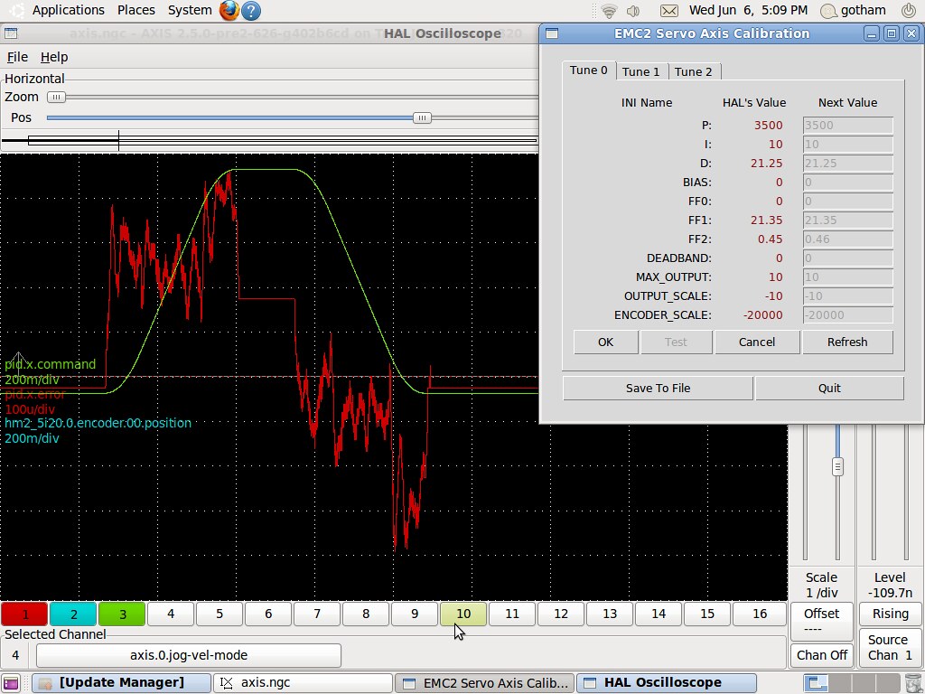
I couldn't find a velocity pin but by looking at the position trace I can see where the axis is stopped, moving at a constant rate, and accelerating. With accel at 15 and doing 100IPM moves the machine doesn't even flinch. I don't think it will be tipping over!
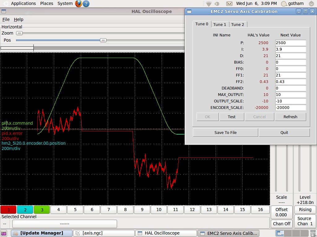
Max accel is 15, 100IPM 1" move and then 1" move back.
X axis (note the scale of the error trace is 200u/div):
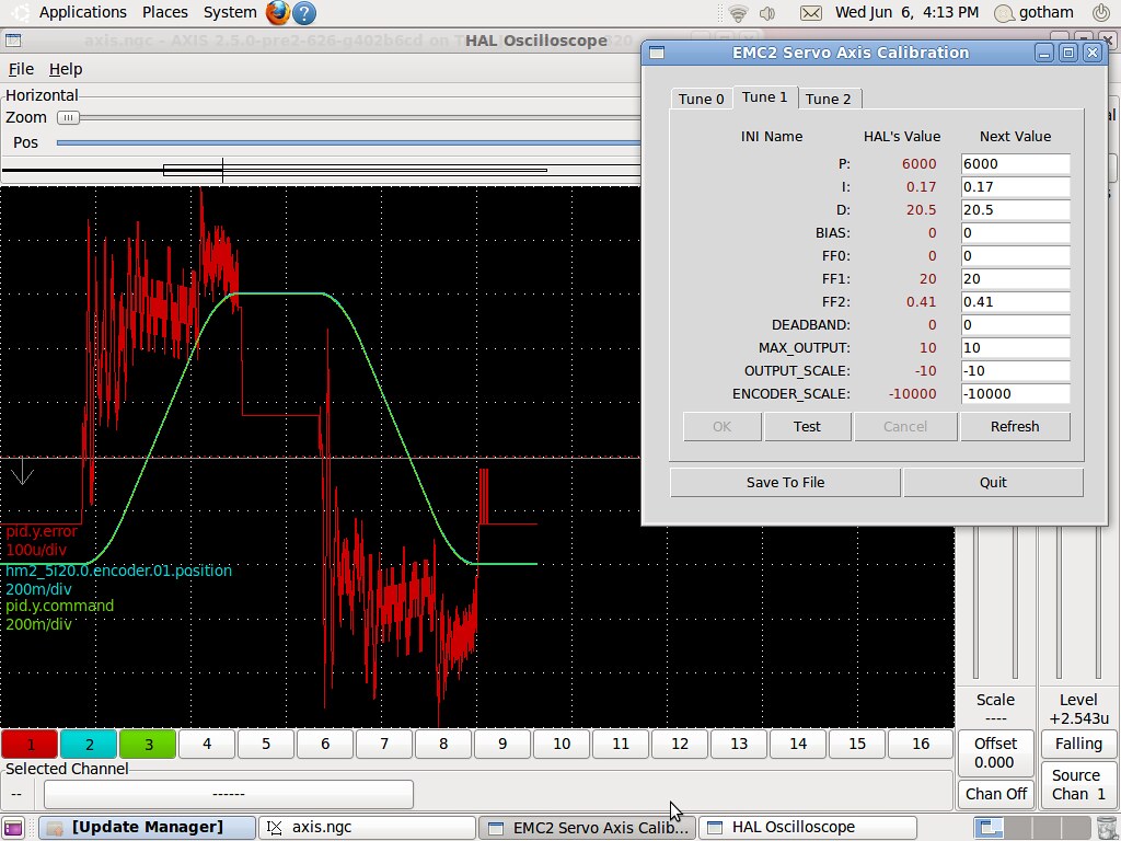
Y axis (note the scale of the error trace is 100u/div):
Where should I go from here?
Sorry for the huge pictures but I think they are necessary.
-
06-06-2012, 10:12 PM #16
Registered
- Join Date
- Apr 2007
- Posts
- 521
I think I made some progress on the X:
-
06-06-2012, 10:14 PM #17
Registered
- Join Date
- Apr 2007
- Posts
- 521
I think I made some progress on the X:
Scale of error trace is 100u/div
-
06-07-2012, 05:59 AM #18
Registered
- Join Date
- Mar 2004
- Posts
- 369
Well, this isn't awful, but you ought to be able to improve it. Note that there is a large Originally Posted by will gilmore
static error between the moves - the elevated flat line in the error trace. that seems
awful strange. With sufficient P gain, that should be closer to zero.
With an encoder SCALE of 20000, that means a single encoder count is
.00005", or 50 uinch. So, an error of 100uinch is only two encoder counts.
You will probably never get better than that.
Jon
-
06-07-2012, 02:14 PM #19
Registered
- Join Date
- Apr 2007
- Posts
- 521
Hi Jon,
Thanks for the reply.
It seems whatever I do from this point makes the error worse. Do you have a strategy I could pursue? I'm also pretty happy with <.0005" error. I'll get the Z axis tuned and check the backlash on this machine to make sure its capable before I worry too much about the small error.
-
06-07-2012, 02:19 PM #20
Registered
- Join Date
- Apr 2007
- Posts
- 521
dp

 Reply With Quote
Similar Threads
-
Servo Tuning HELP!!
By Julian M in forum Servo Motors / DrivesReplies: 1Last Post: 07-18-2010, 01:06 AM -
Servo tuning
By bmlw in forum Daewoo/DoosanReplies: 2Last Post: 05-13-2010, 02:57 PM -
6t Servo tuning?
By Jerry Shorter in forum FanucReplies: 5Last Post: 08-17-2009, 11:28 PM -
SERVO TUNING
By Capteod in forum Servo Motors / DrivesReplies: 1Last Post: 09-17-2008, 04:46 AM -
[Help] : loadusr halscope
By ChandlerBing in forum LinuxCNC (formerly EMC2)Replies: 0Last Post: 12-28-2007, 05:28 AM
