


I thought I would start a new thread as I dig into the mill. This is NOT a bash Novakon thread. They offer a helluva mill for the price. If they did a complete tear-down and performed all the corrections, we would be paying much more for the mill.
I'll have some pictures tomorrow, (I'm sorry..I know this is just a tease so far, but I can't locate my card reader. I'll have one tomorrow).
The electronics were very nicely done, and I like the stainless steel sheathing over the lube lines. The ways on the table and base are nicely ground and very smooth, (unlike the RF-45 type that I had. It looked like they stopped at the rough cut). There were several issues with the lube system that I took pictures of. I noticed that many of the bolts where only marginally tight. They will be put back in with blue loc-tite. I also checked the flatness of the cross slide ways using bluing and a surface plate. There were only patchy high spots, but at least there was no rocking. I started scraping it in tonight on the deck, but the mosquitoes drove me in, (again, I'll have pictures).
Thread: New NM-145 rebuild thread
Results 1 to 20 of 80
-
06-10-2012, 03:09 AM #1
 Registered
- Join Date
- Feb 2010
- Posts
- 371
New NM-145 rebuild thread
-
06-10-2012, 04:31 PM #2
Registered
- Join Date
- Feb 2010
- Posts
- 371
Ok, so here are the promised photographs. Again, I'm not at all disappointed in this machine. I think any Chinese imported machine should be given a go-over and you should expect to find issues that could effect the accuracy and longevity of the machine. But heck, the reason I could afford it was because it had been made with the typical Chinese import care. I will say that from what I've seen so far, it is made MUCH better that others I have seen appart.
Here is a shot of the machine after having removed the Y way covers.

The covers are nicely made, and didn't have any of the weld burn through that I saw in another thread. The rear wiper cover did have a good size wad of iron dust jammed up against the wiper on the inside of the cover. I had wondered where the black streak on top of the cover was coming from.

After removing the covers, I removed the X and Y gibs. The gibs were rather crudely scrapped in. I'll need to correct that later.

I removed the four bolts on each end of the table that hold the two ends of the screw in place, as well as the left table drain. The tapered pins were seated nicely and popped out ok. I then slid the table off the saddle to the right.
The ways on the table were nicely ground and very smooth.

This exposed the lube system from the saddle and the two nuts, along with a free cap screw sitting loose on the cross slide. The picture doesn't show it because I pushed it back down, but the line at the top right had popped up so it was no longer poking into the hole that fed the right Y axis way. The line was also wiggly loose. Just to see how effective the lube pump was, I ended up giving ten pumps and didn't see a drop come out of that line. The line on the right side feeding the X axis nut had a drop for every pump come out of it. Note that the screw was being fed outside of the wiper. There are three lube holes on the nut. The nut in this case had the top lube hole facing down, probably to keep chips from getting into it. I'm going to see about routing the line to one of the side holes. I don't think there is clearance for the line to run to the top of the nut. Also note the three holes on the lower left corner. It looks when they drilled to meet the lube hole, they missed twice. The left hole was the winner.

I removed the X axis nut block so I could get the screw out of the way, then went on to the Y axis nut block. Here I had trouble with one of the tapered pins. Somehow the tip of the pin had gotten serrations.

To remove the table, you need to get the homing sensor box out of the way. There are two screws inside the box that hold it to the saddle. I was able to do it without removing the sensors by first removing the top screw, then rotating the box to loosen the bottom screw. I was able to work the screw out despite the odd angle I had to make with the screw driver.
Next I pulled the saddle out. It's a bit hard to see on the photo, but the original lube feed holes that were centered on the oil groove had been sealed shut. Unfortunately, this also sealed off the groove. Lube being fed in from the one end can't make it past this point. I'll grind or engrave the groove free again. I can't recall now which of the two holes you see are feeding the oil. Obviously, if it's the one outside of the groove, I'll grind a feeder groove to the main groove and plug the other.
More later....I'll show the inside of the column and also some scraping I did on the saddle.

-
06-10-2012, 04:48 PM #3
Registered
- Join Date
- Feb 2010
- Posts
- 371
Novakon did a real slick job mounting the control panel. There are four pins that hold it in place. By pulling two of the pins on the same side, the whole panel rotates away from the column
Here is a shot of the bottom inside of the column showing the lube manifold. The manifold is fed in from the left. The line on the right feeds the manifold on the saddle. The three lines feed both Z axis ways and the Z nut. The Z way feed consists of a hole that passes through to the way. You want the head all the way up when you lube this mill so that the oil gets behind the head instead of simply dripping down the way onto the top of the head. You can see quite a bit of lube that had dripped down from the ten pumps. Obviously the Z is getting most of the lube. I'll need to fix that as well. Again, a real nice job of routing the electronics Novakon.
Lookie there in the lower left in the base, more free hardware !
!

The positive stop for the Z down travel is a rather crudely mounted plate that hits the nut block. I often mill 1/4" plate that is clamped onto another 1/4" spoiler plate. My 1/8" end mill can't make it down far enough to cut through the plate unless I extend the mill out further than is optimal. I thought about relocating this plate an extra quarter inch down, but once I have my TTS in place, the holders will provide the extra length I need.

The homing sensor reads off a plate that is adjustable.

-
06-10-2012, 05:08 PM #4
Registered
- Join Date
- Feb 2010
- Posts
- 371
Time to do some scraping on the saddle.
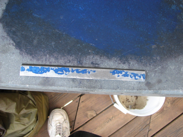
First, I blued up my surface plate.

The saddle had some definite high spots, but it sat flat and didn't rock.

After ten scrapings, it is looking much better, (the bluing is a bit heavy to show the spotting well). I'm going to move onto the other side, and do more on this side later. I have pretty limited time so although it's certainly not a perfect scraping in, I may leave it like this and go back to it some other day. Here you can see some of the tools I used to do this. I have an old BIAX scraper that I bought broken at an auction and fixed. This is its maiden scraping. Also, a hand scraper I made by brazing a large insert to a strip of steel, which is then taped to an oak slat from an old sofa. In the left is an angled piece of surface plate for bluing the dove tails. I bought two plates at an auction, and took one to a granite counter shop. For $20 they put the surface plate on their saw and cut an angle strip off for me. The upside down diamond hone keeps the carbide nice and sharp. Not shown is the stone to smooth out any burrs from the scraping.

Oooh, the Y axis is a bit worse that the X axis. There is an obvious high spot in the lower left, as well as upper right. I'll put it back on the surface plate, this side down and indicate on the other side to see if the X axis ways tilt a bit. I'll concentrate on taking material off the side that levels things out.

More later...
-
06-10-2012, 07:18 PM #5
Registered
- Join Date
- Jul 2007
- Posts
- 675
Thank you for starting this thread. I'm expecting a Torus Pro in a few months. Might have to go the same route you did with the breakdown.
Could you post more information about how you scraped the ways? Particularly how the tool was used to remove the high spots.
Thanks
-
06-10-2012, 08:01 PM #6
Registered
- Join Date
- Feb 2010
- Posts
- 371
I'm pretty much a newbie at scraping. I've worked on two mills and a surface grinder so far. The best thing to do is to watch the utube videos by a guy named muellernick. This guy is a wiz and had much more patience than I have at scraping. He has a whole series of videos that show how it is done. Originally Posted by MRM RCModels

[ame="http://www.youtube.com/watch?v=uHF7TtHVSWE&feature=related"]scraping in a lathe's bed // Bettbrà¼cke einschaben - YouTube[/ame]
Basically, the took is either a piece of carbide, although some use a ground file. It has a slight radius on the end, say that of a six inch circle. The cutting edge is at about a 95 degree angle. The scraping action takes off a very small amount of the cast iron; I'm guessing .00025"-.0005" depending on how hard you bear down. You scrape off the blue spots, wipe off the ink, run a stone across the surface lightly to remove any burrs, and then respot. Eventually you will get to a point where you have blue spots across the whole surface. At that point, you lighten up on the amount of bluing only attack the center of the high spots. The masters at scraping will get a very even distribution of blue and low spots.
Something happened to my biax today. It was getting pretty warm and all of a sudden it cut down in speed. Sometimes I have to rotate the armature slightly to get it going. I must have lost a field on the armature. Hopefully it's something I can fix without having it rewound. the other scraping I had done was all by hand. That sure gets old in a hurry.
-
06-11-2012, 07:45 PM #7
Registered
- Join Date
- Feb 2010
- Posts
- 371
Well, I pulled the motor apart on my Biax today. The reason it was getting so dang hot was obvious. The vent slots and impeller were packed with fiber. I actually thought it was dirty felt for a while. It looks like it must have spent it's life in a textile mill. Originally Posted by AiR_GuNNeR
The armature has stubby short lengths of heavy gauge copper staked and soldered to the commutators. The armature wires are fed down towards the commutators, wrapped in a heavy thread, soldered to the stubs, then the whole mess is imbedded in what looks like a polyurethane resin to keep the wires from flying out from centrifugal force. The excess heat must have degraded some of the resin around the armature wire/commutator stub wires. There are whole chunks of the resin missing, allowing several wires to fling outwards. There were four stub wires completely missing and three had been whipped outwards, but still intact. I was able to rebuild the damaged areas. I plan on putting several wraps of kevlar thread around the area, and then re-coat in a polyurethane resin. Unfortunately, the resin take six days to cure out. I'm considering using super glue as it bonds real well to kevlar, but I know CA can only take so much heat before degrading. I might as well do it right the first time.
I'll put the scraping aside for now and attack the spindle. Although I couldn't feel any lateral play in the spindle, I could feel axial movement.
It feels like the angular contact bearings aren't preloaded.
-
06-13-2012, 01:37 AM #8
Registered
- Join Date
- Feb 2010
- Posts
- 371
Got the biax fixed
With the help of my stereo microscope, I was able to expose the ends of the broken armature field coil wires that had broken, and did a repair of the others that had come loose as well.

I put several tight wraps of kevlar around the wires to hold them in place and put a thick coating of polyurethane resin on them. Then I baked it at 180deg F for four hours.

I repacked the bearing as they were completely dry. They do need to be replaced however. I hope they last long enough to finish the mill.
Now time to get back to scraping!
-
06-13-2012, 02:06 AM #9
Registered
- Join Date
- Feb 2010
- Posts
- 371
Time to scrape the other side of the saddle
Now that I had the saddle's X Axis ways flat and true, it's time to map out the two Y axis ways to see how coplaner they are.
The upper left was referenced as my zero. The upper right ended up being .0014" high, the lower left corner -.0015 low and the lower right -.006 low. So the the two ways are both at different elevations, as well as not parallel to each other.

My plan is to first work on the tapered gib side. I will scrape it to be parallel to the surface plate first. To do that, I scraped two reference dibbits to the "zero" depth, (circled).

Here is the spotting after the third scraping.

And after scraping away the ink spots

About ten scrapings later, I have the way leveled out. The other way was handled the same way to get it parallel to the table. So now, both ways are parallel to the table, but at a different height. The tapered gib side is still high, so the whole surface is scraped down .0015".
Notice how the opposite way is now high on the inside since it tilted that direction by taking off material on the tapered gib side.

And finally, pretty much complete. I may go back and even out the spots later, but this certainly is now flat within .0002"

I checked the inside of the dovetail next. I hate scraping them, and hoped for a very good surface. To my dismay there was a noticeable high spot in the middle to the extent that my master could visually rock. This is after four scrapings

And after eight more scrapings...still a long way to go and the light is fading. The bearings in the biax are sounding a bit shrill again as well. I'll need go put more grease in them and get a replacement set ordered.

-
06-15-2012, 01:07 AM #10
Registered
- Join Date
- Feb 2010
- Posts
- 371
I ground out the filler that had made it into the lube grooves in the ways, as well as ground a path from the oil hole that had been drilled by hand at a very obvious angle and completely missed the oil groove. 3/32" more and the edge of the hole would have gone outside edge of the saddle way.
Well, I finished scraping Y Axis dovetail. The X axis dovetail was a mess too. There were about six sharp high spots.

After six scrapings

After fifteen scrapings

I eventually got it acceptable, but certainly not optimal, (forgot to take a picture). I'll go for optimal at a later time if I still have enough oomph left.
Ahhh, at least they got the table ways right! The lack of ink on the edge was just me not running the master the full length. I could feel that it was nice and flat, in fact surprisingly so. I haven't checked the dovetails....man I hope the're good. That's a lot of length to scrape otherwise. Bluing up the saddle and running it on the table showed the the mating surfaces to be nice and coplaner.

Next I decided to work on the gibs. Holy smokes they are a crude piece of work. This picture masks a lot of the nasty grinder marks. I doubt that I'll be able to get more than 75% of the surface flat because the edges are rounded over. As is is, I'm sure I'll need to scrape enough off both sides that I'll need to put a strip of shim stock behind it in order to get it to fit once I'm done.

This is after 12 hard scrapings. There's a lot to go. The other side is just as nasty.
Once I get both sides flat, it doesn't end there. Next, I'll need to put the gib in the saddle and spot it against the way to see if the taper is correct. As long as I'll need shim stock behind it, I'm contemplating putting three small dabs of JB weld on the back of the gib, put the shim stock on it, let it cure to a stiff putty consistency and then stick in in the saddle, allowing the dovetails to squeeze the JBWeld to the proper taper. Once the three dabs have cured, pop the shim stock off and fill with epoxy the rest of the area.
I may put the scraping aside after I get the gibs done and work on the spindle. As mentioned before, I have a noticeable amount of axial play, and so I'm sure there must be some radial as well, although I can't feel any by hand.
-
06-16-2012, 06:10 PM #11
Registered
- Join Date
- Feb 2010
- Posts
- 371
Finished one of the Gibs
As mentioned earlier, the gibs were really a hack job.
After a lot of scraping on the X gib, this was as far as I could go. The areas that weren't getting any spotting are too deeply sanded away to do any better.

As it is, you can see that taking off several thousands caused the gib to no long fit properly. It now pushes through to the other side and sticks out about 7/8" further than it should. This will actually work well for me as I had planned on gluing shim stock JBWeld and letting the epoxy arrive at the correct gib angle. It may turn out that .002" shim will be too much, in which case I can go ahead and scrape some more.

The Y Gib wasn't any better starting out. It had four VERY distinct high spots.

Here is a closeup of the factory scraping ability.

-
06-19-2012, 02:36 AM #12
Registered
- Join Date
- Feb 2010
- Posts
- 371
On to the head...
The saddle gibs are pretty much finished. I will probably need to go back and dress them up some more if I can't fit a shim behind them to get them back into the proper position for the adjustment screws.
I next wanted to remove the head to scrape the ways, which I have to assume are as crude as the saddle was.
First I removed the spindle. To do this, remove the top cover off the head. From there, you can remove the spindle lock, and then top of the head itself. You will need to remove the E-Stop button wires from the button as well.

Loosen the four motor screws to loosen and remove the belt. Remove the cir clip from the spindle pulley. The pulley was a very nice fit and slid off the spindle with just a bit of force. Remove the four bolts from the bearing collar, exposing the top bearing. Remove the four bolts from the larger bottom ring that bolts into the head and the head should drop out. Mine was a very nice, very slight interference fit, but BE WARNED, yours might not be. Put a stack of wood underneath the spindle just in case it wants to drop out on it's own. In fact, you may want to remove the top collar last for better control.


A few gentle taps with a rubber mallet coaxed the spindle out from the bearing package. I removed the spindle with the intent of adjusting the two angular contact bearings because I could feel some give when I pushed up on the spindle, however, I couldn't feel any looseness to the two bearings, and the spacer that sits between the two bearings on the outer races had a nice firm feel to it when I moved it back and forth. I'll get back the spindle later to figure out where the play came from.
The cable that feeds the head on the left side runs into a cover that also houses the motor cooling fan. I removed the cover and found a bunch of connectors. Great, simply unclasp the connectors and I can remove the head. The connectors will keep me from removing the motor however. Upon closer inspection, I noticed two things.
First, the cover had pinched motor cooling fan wires in two spots, and had in fact pinched right through the wires nearest the fan. The fan 110 volt in series with a thermoswitch mounted to the right and behind of the spindle. When the head gets warm, the fan comes on. I'm glad I didn't run the mill for more than a few minutes. Had the head warmed up enough to try and turn the fan on, depending on if it was the hot side or the ground side, something might have fried. Oh well, no harm done and easily fixed.
The second thing I notices was not all the wires going to the head have connectors. The E-Stop wire runs straight through from the harness through the head. I could have removed the wire and fished it back through, but I decided to cut the wire and install a connector, especially since there was another wire tethering the head to the harness. There is a two conductor cable that has each wire going to the shields on the two different motor harness wires. Once of the wires is soldered to the head end of the harness. I clipped that wire as well and added it to the connector. The odd thing was what I found on the other end of this two conductor wire.
The two ends were soldered together, but hanging loose. I'm sure they were supposed to go to the ground block to help keep down the high frequency electrical noise coming from the motor control wires.

I ran the head up, and removed the right lift gate strut. I moved the head down, and then removed the four bolts holding the Z axis nut to the head. I loosened the four bolts and pulled the two tapered pins holding the Z-Axis stepper block to the column. This gave me enough play to pull the block away from the head as there are two pins holding it in place that you can't get to. Once the head was loose, I was able to push the head to the extent of the strut and tie it off to a roof beam. I removed the last strut and lifted the head off the column.

The head dovetail isn't as bad as the saddle was. I doctored the photo to highlight the spotting since it was too hard to see in the original phot.
The problem is my master for dovetails is cut to fit a 60 degree dovetail. It looks like these are 55 degrees or so. I'll need to use one of the gibs as a master.

The head itself was only riding on four high points....sheesh...it's a shame they did such a nice job grinding the base, table and column ways, only to have it mated up with poor workmanship. I'm going to run an indicator in the spindle hole to see how parallel the spindle is with the ways, and adjust the ways accordingly. I've heard people mention adjusting the column to get the head into tram, but there are two totally different geometries in play here. You must first adjust the column go get an indicator mounted to the head to ride up along a square sitting on the table first. If you have a moveable spindle like a Bridgeport, you then adjust the nod of the head while running the SPINDLE up and down the square, or use a tram. In the case of this mill, you would need to tram it last. I should have checked the column squareness before removing the head. I think I will need to simply flatten the head ways first, and mount it back onto the column, check the column tram, fix if necessary, then check the head tram and calculate how much of an angle needs to be scraped into the ways.

Did I mention loose screws? Most of the SHCS that I had removed thus far were only moderately tight, and a few only slightly tightened. The screw holding the vent cover in place on the lower right would eventually have found itself on the table. You can tell it didn't work itself loose during shipment because there is paint right up the exposed thread.

We are having a "Techno toy Show" on the 25th at work and I plan on taking in my scraping equipment where I'll demo how, what, and why scraping is done. Consequently, I won't have any scraping pictures until after next week.
In the meantime, I will go through the electrical panel to see if anything there needs attention.
-
06-29-2012, 01:37 AM #13
Registered
- Join Date
- Feb 2010
- Posts
- 371
Scraping in the head ways
This is how the ways on the head started off. The head is sitting on only four tippy toes. I'd like to up that by at least a factor of 100.
I scraped in the ways on the head until I had a pretty good base to measure off of. What I wanted to measure was how parallel the spindle bore is to the head ways. This in effect is making sure that the head's "nod" is set perfectly.

With the head sitting on the surface plate, I first lowered my .0005"/div indicator into the bore. A little shifting of the head from side to side will tell you when you are indicating off the bottom of the hole. The indicator is zeroed out at this position.

Then, carefully shifting the head over to the other side, I snuck the other end of the bore under the indicator needle. Not too shabby at all! It looks like I only need to adjust for about .00075" over the length of the head, or probably .001" over the length of the ways. This head is currently nodding up.

To fix this tilt, I figured on eight scrapings to remove the .001". I mentally divided the way into five parts down its length. The first scraping reached 4/5ths up, and each subsequent scraping went one zone less up the length of the way. This procedure was repeated twice and then the head was checked again. At this point it was less than .00025" off.
After that it was was back to whole surface scraping, favoring the high side a bit.
This is the second scraping reaching up to the 3/5ths mark.

I mentioned earlier that I was going to check out the electronics. Everything looked great in that department. The only thing I changed was I replaced one ground wire that ran from the panel to the column that was a bit short and limited how far I could swing the panel out.
-
07-04-2012, 02:05 AM #14
Registered
- Join Date
- Feb 2010
- Posts
- 371
Getting the mill off the stand
The next thing I need to do is check the fit between the head dovetail and the column dovetail. I tried to do this by bluing the column, lifting the head onto the column, and running it up and down by hand, but it just took too much out of me to do it more than a couple of times.
Since I had planned on taking the base/column off the stand anyway to get it into the basement, I decided to make that my next plan of action. That way I could set the mill on the back of the column for much easier bluing of the mill head. To do this, I would also need to remove the control panel.
The control panel is pinned to two cross members that are bolted to a substantial casting that is bolted to the back of the column. By removing six bolts, I could separate the casting from the back of the column. Looking at the various wires it looked like I could separate the two without too much unwiring. First the connectors were unscrewed from the stepper, the ZAxis proximity sensor wire was unscrewed from the sensor, the oil manifold was unbolted and the main oil line going to the oiler removed. I also removed the oiler. The only wires that I needed to physically undo from the control panel was the coolant pump wire that goes to the relay, and the ground block wires. I wrapped a sling around the control panel and hoisted it up with my deer winch. (I had a better picture, but deleted it accidentally). It looks like I only have the strap wrapped around the casting, but it actually goes around the control panel once on each side of the casting.

That probably reduced the weight by 150lbs.
Next I put two rods through the mill base for the sling.

I had planned on using an engine hoist to lift the mill off the stand, but the legs wouldn't straddle the shipping pallet. It was time to get rid of the pallet. This went easier than I had first thought. I put a piece of wood in front of the pallet and slid the mill over the edge of the pallet onto the wood. I slid it far enough that I could push the back end of the stand up off the pallet, and kick the pallet away. In a similar fashion, I rocked the wood out from underneath as well.


Now to lift the mill off the stand and get it onto my rolling tool box. I wrapped the sling around the rods and lifted it off the stand onto the floor.

I then passed the sling through the opening at the bottom of the column and lifted it to tool box height. The balance turned out perfect in that I could swivel the mill over onto it's back while in the air.

Man, I'm sweating like a pig. It's 100% humidity and 92 degrees here in Michigan right now. Time for am ice cold Leinenkugel Summer Shandy. Tomorrow, I'll blue up the column dovetails and start spotting the head to see how well its angle matches up.
-
07-05-2012, 03:24 PM #15
Registered
- Join Date
- Feb 2010
- Posts
- 371
 More Head Dovetail Scraping
A few posts down, I established that the spindle bore was aligned very close to the ways of the head in the "nod" direction. Now that I am working on establishing the dovetail angle to match that of the column, I also want to be sure that the dovetail is aligned with the bore so that the spindle will have no tilt.
At this point I plan on laying the head on its side, measuring establishing a relative height difference off of dowel pins laid in the dovetail, and see if I have the same height difference off the spindle bore. As I scrape in the dovetail, I will favor the side to correct for any tilt.
Let me ask you guys, are pictures kind of lame at this point since I've had so many scraping pictures already? I'll take some as I get into this process if there's any interest.
-
07-05-2012, 05:55 PM #16
Registered
- Join Date
- Oct 2011
- Posts
- 61
Please keep the photos coming. It helps me greatly to understand the procedures involved and the relationship of the various parts to each other. Being a new owner of an NM-145 your hard work is greatly appreciated. Thanks very much for posting all this information.
Curtis
-
07-06-2012, 06:47 AM #17
Registered
- Join Date
- May 2011
- Posts
- 308
Yes, please keep the photos and info comming. I find this really informative.
Thanks!
-
07-07-2012, 12:01 AM #18
Registered
- Join Date
- Feb 2010
- Posts
- 371
Measuring the spindle tilt angle error
Well, it's a humid 98 degrees here in Michigan, so I only took enough time on the deck to perform some measurements and take some pictures. I set the head up on the surface plate with a 123 block under one end. I'll be taking relative measurements from one end to the other so it doesn't matter if the head isn't parallel to the block. The difference in height should be the same for the dovetail and the bore of the spindle.
I took a dowel pin sized to hit around the middle of the dovetail.

I aligned the end of the pin with the bottom side of the head, which is also the bottom of the spindle bore and zeroed out the indicator.

Then, moving the pin to the top of the head, aligned with the top surface of the head, I took another reading, (by setting the pin up this way and taking reading, the distance between the readings is the same as the depth of the spindle bore). This showed a .0015" tilt to the head as I had it sitting on the plate.

Next, I measured the tilt to the spindle bore. Zero the indicator out first.

Moving around to the other side of the bore, I get .0025" tilt. So over the length of the bore, I am out only around .001". Since the dovetail is longer than the head, I am only less than a thousands from one end to another. That's not too shabby at all, but as long as I am correcting the dovetail angle, I may as well shave off a wee bit more from one end than the other and get it dead nuts on.

-
08-08-2012, 01:22 PM #19
Registered
- Join Date
- Feb 2010
- Posts
- 371
Lack of activity
Sorry for the lack of activity in this thread. I chanced across an Emco V13 lathe in pristine condition. I've been pining for one of these for eight years and had to act on it. If anyone is interested, the acquisition thread is here:
Got a killer deal on an Emco V13 today...
And I also have a current installing a DRO thread here:
Emco V13 DRO mounting thread
I have both the lathe and the 145 mill in my garage right now. The lathe goes all the way to the back of the basement, so I have to get that in shape first and ready to install before I can continue on with the 145. I have started on fixing the gibs and have pictures of that which I will post soon.
-
08-25-2012, 03:02 AM #20
Registered
- Join Date
- Feb 2010
- Posts
- 371
Well, my weekends have been shot as far as working on my machinery. I did steel a few hours and continued work on the gibs.
Recall that with all the scraping, the tapered opening for all the gibs have opened up. Pushing the Y axis gib in place showed it protruding well over an inch past the point is should have stopped. I set the gib in the position it should be in and with an indicator on the edge of the saddle, shoved the saddle from side to side. I had around .014" slop.
To recap, what I had planned was to put some firmed up JB Weld between the gib and a piece of shim stock, then push the gib into place. This will cause the gib to find its correct angle and force the excess epoxy to the proper thickness as well. In the end, I bought some of the plumbers type JBWeld that you cut a chunk off of and kneed it. the shim stock was cut to shape, and allowed to overlap the ends to keep it in place.
The working time is pretty short, but that was ok. This stuff was almost too stiff. I had to push the gib in, wait a second for the putty to flow, push some more, wait, etc. Once I had it in far enough to get the gib screw to bite, it went a lot easier. I used four spots of epoxy. Once it had cured, I pulled the gib and removed the shim stock, (I put silicon grease on the shim stock, and cleaned the back of the gib real well). I did the table gib as well, but had more trouble with that one. I thought it would be a bright idea to warm the epoxy slightly so it wasn't so stiff. Warming it made little difference to its stiffness, but as expected, sped up its cure time to a point I barely had it in place before the putty wouldn't flow anymore.

Now that I had pads established, I added some more putty to fill in most of the gaps, reinserted the gib, let the epoxy cure, removed the shim stock, and honed the pad to even height, (the second application ended up a few thou thicker).

There are other things that will need to be adjusted due to the scraping. Since the table and saddle are moved over, the tapered pins that pin the ball screw nuts in place are no longer located correctly. I have a 6mm tapered reamer on order. I'm going to see if I can clean up the hole. Metric tapered pins have a 50:1 ratio, so a little hole diameter increase greatly increases the depth that the pins seat. I suspect I may end up having to order larger pins, perhaps 7mm, or a next greater imperial size like a #4 or #5.
I can't seem to find these in any reasonable low quantities, so I may end up turning them on the lathe out of drill rod.

 Reply With Quote
Similar Threads
-
Thread spec for camera lens filter thread
By cmays in forum MetalWork DiscussionReplies: 6Last Post: 07-20-2016, 10:43 AM -
Thread Mill Wizard - Slanted thread produced
By ngr1 in forum Mach Wizards, Macros, & AddonsReplies: 5Last Post: 07-22-2012, 07:23 PM -
X2 rebuild soon to be CNC'd
By 1HobbyMachinist in forum Benchtop MachinesReplies: 5Last Post: 03-03-2012, 05:43 AM -
acme thread combos and thread mixing
By calaber40 in forum Linear and Rotary MotionReplies: 5Last Post: 05-16-2009, 02:04 AM -
rebuild help
By houdini in forum I.C. EnginesReplies: 6Last Post: 04-14-2008, 02:16 PM
