


Perfect!
Thread: Ryan's g0704...
Results 221 to 240 of 284
-
09-28-2013, 10:10 AM #221
 Registered
- Join Date
- Sep 2006
- Posts
- 607
-
09-28-2013, 07:41 PM #222
Registered
- Join Date
- Nov 2012
- Posts
- 220
Ryan, I know I am late saying this but thanks for the after-action review. It is cool to see what you liked and didn't. By the way great job on the sheet metal! I could tell you were into computer modding as soon as I saw the design for your enclosure. Originally Posted by 691175002

-
09-30-2013, 09:04 AM #223
Registered
- Join Date
- Apr 2005
- Posts
- 419
Time for a little more sheet metal work. I wanted sort of a hybrid pendant/control panel type box. Something small enough to be moved around, but that has enough functionality to work as a full control panel for my mill.
Empowered by my previous sheet metal success, I drew up a matching box in CAD:
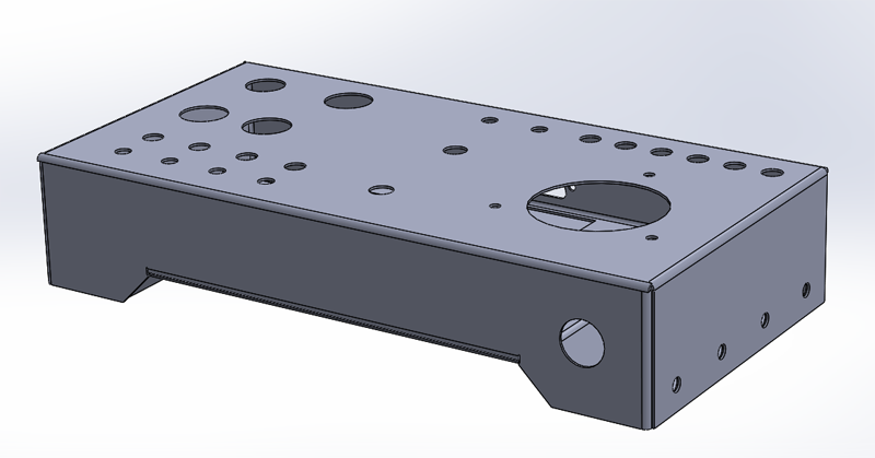
I wanted to avoid screws on the top and front of the box for aesthetic reasons, so the box is made of two components. The top portion has a fair number of folds that must line up properly.
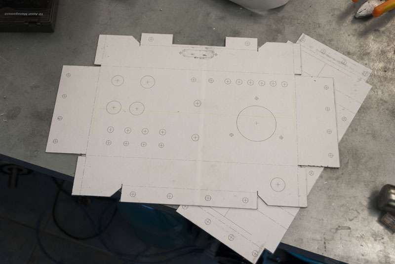
This time I also included some registration marks when printing the flat patterns.

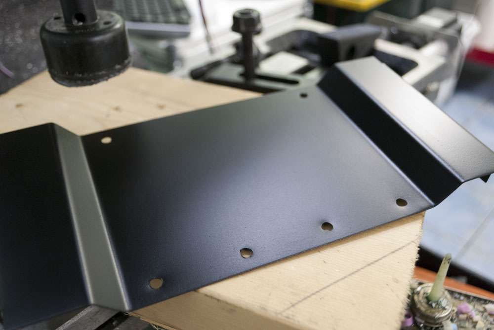
After gluing the patterns to the sheet metal, I cut it with a mixture of a bandsaw and the shear in my 3 in 1 machine.
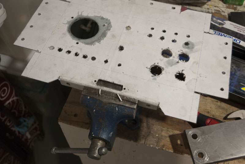
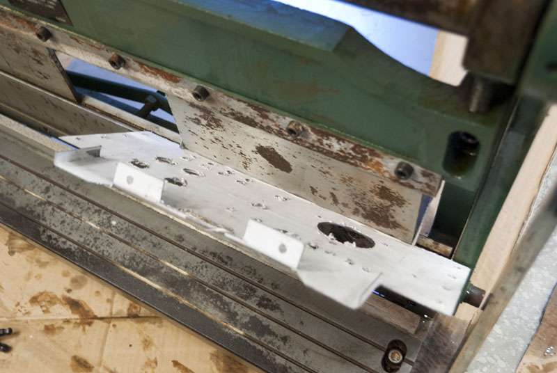
Some of these bends cannot be done using my 3 in 1, so I had to resort to a vice, pieces of flat bar, and a hammer.
The 3 in 1 got left outside for the winter but still works fine.

And here are the finished parts:


Also picked up some paint, I decided to use Krylon Satin Black Paint+Primer. I don't want to get caught up in an involved paint job so I just roughed everything up a bit and wiped it down with acetone.
I really like the diffuse shinyness of satin paint.
I've been designing the parts to use these captive nuts but I've never tried them before so hopefully they work properly.
McMaster-Carr
-
09-30-2013, 12:44 PM #224
Registered
- Join Date
- Jan 2008
- Posts
- 1529
What thickness is that sheet steel?
Looks great.7xCNC.com - CNC info for the minilathe (7x10, 7x12, 7x14, 7x16)
-
09-30-2013, 02:39 PM #225
Gold Member
- Join Date
- May 2005
- Posts
- 3920
I pop into this thread from time to time and all I can really say is fantastic work. Having gone the vise / hammer route for sheet metal work in the past I can say you are a master with the hammer. The only thing that bothers me about your case is access for initial debug, is it possible to pull out the panel to get good access? Maybe it doesn't matter with access doors all around but I just don't like having to reach around frame members and the like to access test points and the like.
The panel box however looks fantastic with the precision work and innovative design.
-
09-30-2013, 02:54 PM #226
Gold Member
- Join Date
- May 2005
- Posts
- 3920
It is a little late to be responding here but some concerns I have will be highlighted below.
Weight should have nothing to do with selecting a power supply. The power supply should be able to handle servo or stepper drives and any possible bus voltage rises that those drives may cause from regeneration or other voltage feed back to the power supply. This is important because voltage rise may damage the power supply in a number of ways including triggering a crow bar circuit if the supply is supplied with one. If not damage it may cause odd behavior from the regulated supply. Originally Posted by 691175002
This is why servo amp manufactures often recommend simple unregulated supplies. If not that at least go with a switching supply designed for use with servo/stepper controls.
I see further on in this thread that you really didn't like KFlop. More details there might help people decide if KFlop is a problem for them or not.No display in the box, a laptop must be attached for machining. I used the KFlop since I was able to borrow it from my g0704. EMC2 on a miniitx board would be pretty awesome as well.
Not really that bad though.I got sidetracked for a few days, but I have performed the first few cuts on the machine. Did some pocketing/profiling in acrylic which went very well and some test cuts in aluminium.
I can run approximately 9IPM, 0.020"doc slotting a 1/8" endmill in aluminium. This was with the spindle at 30% duty cycle since I have not fully broken it in. I can probably go faster, but I don't know how the RPM varies with duty cycle.
Its a fairly pathetic cut, but the finish is good and I'm willing to wait for slow cycle times.
Repeatability and backlash are both better than 0.0005". I tuned the machine for 90IPM rapids and 20"/s acceleration. The motors can probably go a lot faster, but the acceleration seems near the rigidity limit of the frame.
-
09-30-2013, 04:19 PM #227
Gold Member
- Join Date
- Jul 2007
- Posts
- 1602
I think his issue was more with KMotion than KFlop. Originally Posted by wizard
bob
-
09-30-2013, 08:58 PM #228
Registered
- Join Date
- Apr 2005
- Posts
- 419
So far I have been using a mix of 22 and 20 gauge sheet metal. I would have preferred to go a little thicker on the case, but my 3 in 1 is limited to 20ga. I can buy 16ga very cheaply since the scrap yard stocks full sheets (right now I go to princess auto or metal supermarkets which is extremely expensive), but I have no way of working it which is unfortunate.
Attaching the back panel to the bottom of the case was probably an oversight on my part. I will likely do most of the work outside the case and put it all together at the end.
In KMotionCNC when you type something into the MDI and press enter, the command gets executed but the text box does not clear. So when I am typing a bunch of lines into the MDI, I have to select and delete the line I previously typed every time which is super annoying.
There is also no spindle speed override (or even spindle speed display), and no way to estimate program runtime. The whole interface fits on one screen and is extremely bare bones. I could probably add all the functionality I need, but I don't really want to be reinventing half of mach3/emc2.
As well, a lot of the interface gets delayed by the interpreter look-ahead so adjusting feedrate, feedhold, etc... all get reflected 2-5 seconds late.
-
09-30-2013, 09:22 PM #229
Gold Member
- Join Date
- Feb 2006
- Posts
- 7063
If you have all the C-code needed to get KMotionCNC running, it should take about an hour or two to bring up Mach3, using pretty much all of the same code.... I had no trouble writing code that would work for both for nearly all functions. Originally Posted by 691175002
Regards,
Ray L.
-
10-01-2013, 10:56 AM #230
Registered
- Join Date
- Apr 2005
- Posts
- 419
I've been meaning to make the switch to KFlop + Mach3 for a while but never got around to it. I'll probably make the jump once the machine is running again.
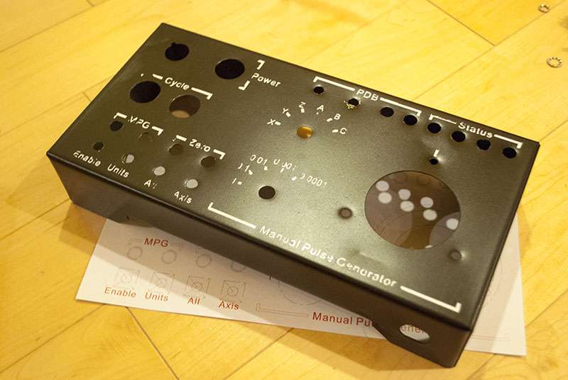
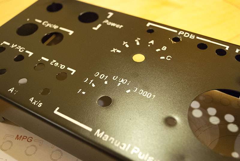
Just some paint today. First up are some of the case pieces:
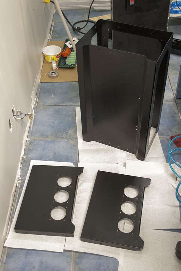
And test fitting some of the parts:

Putting lettering on boxes is one of those small things that always seems really hard to do. As far as I'm aware, there are really no options for one-off parts (especially on top of black). I decided to try something new and wrapped the box in transfer tape then laser cut it:
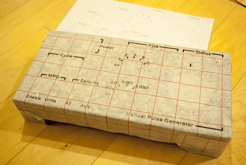
A few coats of glossy white later:
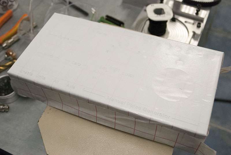
And a massive failure:
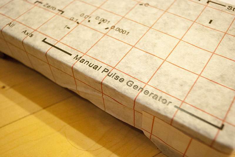
A lot of the paint peeled off with the mask, I suspect that the laser left burnt glue residue on the box. I should probably have wiped down the case with alcohol/acetone before painting, and perhaps I should try a different mask material.
It would only take a few hours to sand it off and try another go but I'm not sure if its worth the effort. As is, the lettering is readable enough to serve its purpose and it doesn't actually look that bad since its consistently grungy.
-
10-01-2013, 01:35 PM #231
Member
- Join Date
- Sep 2008
- Posts
- 229
And if you are happy with C, perhaps LinuxCNC is worth a look? Originally Posted by SCzEngrgGroup
(Not that there is any need to write C to use LinuxCNC, but if you can program in C then you can _rewrite_ chunks of LinuxCNC to do anything you want.)
As a heads-up, LinuxCNC currently has experimental support for the Mesa 7i80 and 7i76E boards (that connect via the ethernet port). This should be included in the next full release (but don't hold me to that).
Actually, the 7i76E looks like it might be good for Mach too (5x 10MHz stepgens, spindle VFD controls, 48 x 24V-safe IO lines)
-
10-02-2013, 03:47 AM #232
Registered
- Join Date
- Nov 2012
- Posts
- 174
Really nice work all around on this build. For the control box lettering, something we've done at work for labelling custom control boxes is to print the labeling onto a transparency sheet and trim it to fit the top of the box. A little clear glue around the edges and the panel mount hardware help hold the transparency in place. Most printers don't print white, so we usually use a bright yellow that shows up good against the black. --md Originally Posted by 691175002
-
10-02-2013, 04:48 AM #233
Registered
- Join Date
- Jul 2012
- Posts
- 80
For box lettering you can get inkjet printable vinyl and a transparent overcoat layer that makes it waterproof from Papilio. I've used it for creating panel labels, and it works very well. This is the same material that is usually used for making full color billboards.
The other method, is to use a vinyl cutter to cut out the lettering out of vinyl, and stick it to transfer tape for application onto the panel. Large signs on automobiles are frequently done this way. Maybe you could figure out how to do this with a laser cutter, if you can cut through just the vinyl, but leave the backing intact.Michael Anton
http://manton.wikidot.com - http://laserlight.wikidot.com
-
10-02-2013, 05:19 AM #234
Registered
- Join Date
- Apr 2005
- Posts
- 419
I have been planning on giving LinuxCNC a whirl if I ever get around to building a new machine. I have actually been slowly picking up ground ballscrews and linear rail off ebay but I don't know if I will ever reach the point where I can think about yet another build. I love the look of their toolpath display (showing the dimensions/origin) and those mesa boards look awesome.
I took a look at hobby level vinyl cutters and the silhouette cameo looks pretty good. I never realized they had become so cheap, I'll probably pick one up next time I need lettering or other vinyl stuff.
-
10-02-2013, 05:57 AM #235
Registered
- Join Date
- Jul 2012
- Posts
- 80
That's interesting that you've looked at the Cameo. I've been doing the same, except for a different purpose. There was a guy at the Maker Faire that was using one to make SMT solderpaste stencils, and it seemed to work really well. I'm tired of paying $150 for a lasercut stencil for building a few prototypes. At that price, I can buy a Cameo for the cost of a couple of stencils.
Michael Anton
http://manton.wikidot.com - http://laserlight.wikidot.com
-
10-02-2013, 08:28 PM #236
Registered
- Join Date
- Dec 2012
- Posts
- 390
Just don't use the Silhouette software for the cutting. It's terrible for cutting the stencils. There's a program made by someone that does a much better job. It is much slower, but I prefer to get proper looking stencils than stencils with skewed pads. I can't remember what the program is called, but you have to go via a PS-file. Originally Posted by manton
Edit: Link to the script and link to a forum post about how to run it on Windows.
-
10-02-2013, 10:13 PM #237
Registered
- Join Date
- Oct 2011
- Posts
- 42
One easy method of labeling things like this is simply to print your design on paper, then put some perspex on top of it and secure the perspex down somehow (rivets/screws/whatever). Makes it quite easy to change the labels etc as well.
-
10-03-2013, 12:04 AM #238
Registered
- Join Date
- Sep 2013
- Posts
- 88
Ryan,
Back when I had a laser cutter handy I used some neat products for marking metal.
It's a type of black paste that you apply and then etch with the laser to bond it to the metal (one example is CerMark)
Probably not useful for your current design, but if you made the front panel in raw stainless or Al. then you could use this method.
The resulting marking is very very durable.
-
10-03-2013, 11:10 PM #239
Registered
- Join Date
- Apr 2007
- Posts
- 101
Have a look at Rowmark laser lettering acrylic sheets. Rowmark - LaserMark Product Line
I've used it to add labels to a custom DRO I made. I used the mill to engrave the lettering so its not 100% perfect in my case. One tip to get perfect results with a laser if you don't have a fume extractor is to apply masking tape so the smoke doesn't leave any marks on the surface.
You can spray the back with adhesive if you don't use any mounting hardware and touch up the sides with black paint to hide the white layer.
Attachment 203290-Leo
-
10-04-2013, 02:44 AM #240
Registered
- Join Date
- Apr 2005
- Posts
- 419
Thanks for all the great advice for marking panels.
I did some fairly simplistic work mounting limit switches and moving wires around. The X axis had a bit of trouble going to the extreme limits of travel but I fixed it up. Looks pretty messy but its reliable and it will be completely covered.
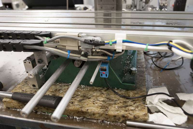
Also mounted and tested all 5 limit switches:

I'm using the inductive type and they were repeating to within 0.0001" on my MPG. I don't know if they will drift over time but seems fine for now.
I've been putting off the electrical work because it feels really intimidating to start taking a working piece apart, but it's time to bite the bullet and hope I don't let out any smoke.

 Reply With Quote
Similar Threads
-
G0704
By kd4gij in forum Benchtop MachinesReplies: 8Last Post: 07-07-2016, 12:00 AM -
DRO for G0704
By UMR in forum Benchtop MachinesReplies: 4Last Post: 07-06-2016, 04:04 AM -
No Joy with my New G0704
By DogWood in forum Benchtop MachinesReplies: 5Last Post: 07-05-2016, 05:49 PM -
G0704... Yes Another One ;)
By ww_kayak in forum Benchtop MachinesReplies: 24Last Post: 05-27-2013, 03:47 PM -
G0704 or a X-3
By USN in forum Benchtop MachinesReplies: 8Last Post: 05-30-2011, 08:24 AM
