


Friends,
I jog my machine and found :
X0 = 1.0238"
X1 = 4.86"
Y0=0.1247"
Y1=2.5"
Z0=0.5272"
Z1=1.0440"
How can I configure Xmin,Xmax, Ymin,Ymax and Zmin,Zmax,home in configuration ?
I'm using EMC on Linux CNC, and if in G-code Ymin = -0.12",
How can I configure it ?
Thanks for help
Results 1 to 10 of 10
-
07-03-2012, 03:25 PM #1
 Registered
- Join Date
- Apr 2012
- Posts
- 45
 How to configure home for x,y,z ?
-
07-03-2012, 07:40 PM #2
Registered
- Join Date
- Jan 2005
- Posts
- 1943
I don't know if I am fully understanding your question, but I will give it a try.
The machine limits are defined in your configuration file. The easiest way to set these up is using the step configuration program. For each axis you define how much travel the axis has from the home location. For example, if the x axis home position is at one end of the total physical travel and the table can move 8 inches in the positive direction, then you define that on the page for the x-axis in the step configuration program like in the first picture attached.
When you start up the machine you have to "home" each axis. This is accomplished either automatically if you have home switches, or you position the axis by jogging to the home position and then pressing the home button. Once "homed", LinuxCNC then knows how far it can go without reaching the physical limits of the machine.
When you place your part on the machine to be machined, you then set a zero position for the part. You do this by positioning the machine where the part zero is supposed to be and selecting the "touch off" button for each axis. Once this is done, LinuxCNC knows where the part is located on the machine.
Once you load your program, LinuxCNC will evaluate the g-code to determine if all of the tool paths are within the physical limits of the machine. If they aren't you will get an error. If your machine limits are defined correctly in the step configuration wizard then the only recourse you have is to re-position the part so that all of the code is within the machine limits.
In most if not all cases, Home is not the same as the part zero location.
-
07-03-2012, 11:15 PM #3
Registered
- Join Date
- Apr 2012
- Posts
- 45
X0,Y0,Z0, are the minimum distance for the machine and X1,Y1,Z1 are the maximum distance of the machine,
How can I determine on stepconf, Xmin,Xmax,Ymin,Ymax,Zmin,Zmax ?
Just enter those values ? The issue is, if there's a negative value in G-code,
what should I do ?
For example Ymin in G-code = -0.18 and Zmin = -0.08 ?
Thanks
-
07-04-2012, 06:37 AM #4
Registered
- Join Date
- Jul 2009
- Posts
- 419
You tell steconfig what those values should be in my case I have 870 mm of x travel and I want my 0 to be a the tables edge.
That means table travel is -125 to 745 with home at 0.
It took me quite sometime to comprehend toutch off. What you do is move the axis to where it needs to be, press touch off and then enter the position it needs to be:
So if the screen says the tool is a x345 and according to the screen the part is at X200, click touch off and then enter 200. The image on the screen changes and shows the part at the position of the tool but the system still remembers the mills limits.Sven
http://www.puresven.com/?q=building-cnc-router
-
07-04-2012, 08:52 AM #5
Registered
- Join Date
- Jan 2005
- Posts
- 1943
I will try to explain it using just the x-axis as an example. Refer to the text and the attached picture.
First you have the physical limits of the axis denoted by the red lines. The machine can't go any farther or something hits something. simple to understand. For this simple example lets say the total mechanical travel is 10.000 inches.
Next you have the software limits of the machine denoted by the black lines. These are what you define in stepconf. I'll get to the determination of numbers later, but these are the limits defined in the software and LinuxCNC won't knowingly drive the axis past these points. These software limits should not be outside of the mechanical limits of the machine. Generally you leave a little room between the software limit and the mechanical limit. Lets say you use a 0.100 inch buffer at each end. That means the total travel as far as the software is concerned is 10.000-0.100-0.100=9.800 inches
The home position is somewhat arbitrary. Home can be anywhere within the travel bounded by the black line. It is generally at one end or the other. This is denoted by the purple vertical line in my drawing. This can be a bit confusing so pay attention here. I assume you have a stepper driven machine. If so, then when you first turn on the computer, LinuxCNC has no idea where the table is positioned. You have to give it a reference. Think of it like someone taking you onto a football field blindfolded and asking you how far from each goal line you are. You have no idea until you take the blindfold off and look at the field markings and see you are on say the 40 yard line closest to the home teams goal line. You being blindfolded not knowing where you are is like LinuxCNC is when first turned on. You taking the blindfold off and seeing where you are is like pushing the home button for the axis in LinuxCNC. It gives LinuxCNC a reference to know where the axis is positioned. The only thing is that you have to position the machine in the same position every time you perform the homing procedure. This can be by jogging to that position, by manually cranking the table to that position, or if you have home switches LinuxCNC can move in one direction until it trips the switch and sets home itself. For this example lets say that you want home for this axis to be 4 inches from the mechanical limits on the left (negative) end.
Now we have enough to figure out what to put into stepconf for this axis. First, you have to decide what value you want to give for "home" for this axis. It can be any value you want, but most people say that the home position is machine zero, so in this example, the purple line is machine 0. That means that the left mechanical limit is -4 inches from machine 0 and the right mechanical limit is +6 inches from machine 0. What about software limits. Remember for this example we have a 0.100 inch buffer between the mechanical limit and the software limit, so the left software limit is -3.9 inches from machine 0 and the right software limit is +5.9 inches from machine zero. Guess what!!! We now have th numbers to put into stepconf for this axis. On the page to define the axis like I posted earlier you would put the following values in:
Home location = 0
Table travel -3.9 to +5.9
Now lets say that instead of the home location having a value of 0 we want it to have a different value. Lets say we want it to be +7, which is just a number I picked. With that value would you put in for table travel in stepconf? Well you can go left from home 3.9 inches before you get to the left software limit and that hasn't changed because the actual home position hasn't physically changed, we only changed the value we gave it. Since we are going toward the left that is negative so we subtract. 7-3.9=3.1. Likewise you can go right from home 5.9 inches before you get to the right software limit. This is going in the positive direction so we add. So 7+5.9=12.9. For this example, the values that you would put into stepconf would be:
Home location = +7
Table travel +3.1 to +12.9
This isn't a logical definition, but you could do it that way. One last example that would be more logical would be with home in this example having a value of 3.9 then doing it the same way, the values for stepconf would be
Home location = +3.9
Table travel 0 to +9.8
I hope that explains this part of it, but we aren't done.
The above stuff all references "machine coordinates", but there are also "part coordinates". Part coordinates can be really whacky compared to machine coordinates, but for simplicity we will just talk about part coordinates being just an offset from the machine coordinates. Lets the part coordinates partX, partY and partZ respectively. Setting up part coordinates is really pretty easy. Look at my picture again. The blue blob represents the part, and the green line represents how far the table has to travel to do the machining of the part. The green line has to be between the software limits of the machine or linuxCNC will give an error. Lets say your g-code program is written so that the left end of the part is the partX location. Once all of the axes have been homed and linuxCNC knows where it is, you jog the machine to position the center of the tool over the left edge of the part and hit "zero axis". That's it. You do the same for the Y-axis to set partY. PartZ is generally where the tip of the tool just touches the top of the part. The only caveat is that the zero locations for the part are dependent on how the program is written.
Now you have the machine set up and the part located and part zeros set. Now you have to understand a little about how LinuxCNC thinks. LinuxCNC has more part coordinate systems than just one. It actually has 9 part coordinate systems and it uses G-code to know which one it is using at the time. In addition there is the machine coordinate system. The G-codes that reference each coordinate system are as follows:
G53 - machine coordinate system
G54 - Part coordinate system #1
G55 - Part coordinate system #2
G56 - Part coordinate system #3
G57 - Part coordinate system #4
G58 - Part coordinate system #5
G59 - Part coordinate system #6
G59.1 - Part coordinate system #7
G59.2 - Part coordinate system #8
G59.3 - Part coordinate system #9
When you use a G53 command LinuxCNC knows to make its moves based on the "machine coordinates". For example, if you have a line of G-code that says :
G53 G0 X0
The machine will make a rapid move to X=0 referencing machine coordinates.
if you just use
G54 G0 X0
the machine will make a rapin move to X=0 referencing part coordinates #1.
G53 is a one time use (non-modal) where the other are modal. What this means is that every time you want to make a move using machine coordinates you have to use the G53 code. For the others LinuxCNC remembers which one of G54 through G59.3 was used last. For example, this code sample:
G55 G0 X2.1
G0 X5
G53 G0 X0
G0 X4
The first line sets part coordinate system #2 (G55) as active and makes a rapid (G0) move to X=2.1 with reference to the G55 coordinate system
The second line makes a rapid move (G0) to X=5 with reference to the G55 coordinate system since it was activated in the previous line.
The third line sets the machine coordinate system (G53) as active and makes a rapid (G0) move to X=0 with reference to the G53 coordinate system
The forth line makes a rapid (G0) move to x=4 with reference to the G55 coordinate system. Why the G55 and not the G53 coordinate system? It is because G53 is non-modal or one time use and then it reverts back to the previous coordinate system. In this case G55.
G54 is the default part coordinate system when you turn the machine on and is generally the only one you need if you only run one part at a time. You use the other mostly for when you are running multiple parts at a time.
-
07-04-2012, 12:22 PM #6
Registered
- Join Date
- Jul 2009
- Posts
- 419
Wow, that is great info, thanks!
Do you enter offsets in to each Part coordinate system by choosing the corresponding G5* when touching off?
So you could write
G55 Call "subroutine"
and then
G56 Call "subroutine"
for the same thing in a different location?
Are the offsets stored, are they still in the system after rebooting the system?Sven
http://www.puresven.com/?q=building-cnc-router
-
07-04-2012, 01:02 PM #7
Registered
- Join Date
- Apr 2012
- Posts
- 45
Do I put the right configuration ?
I still get unreachable Y axis for this code :Code:[AXIS_0] TYPE = LINEAR HOME = -1 MAX_VELOCITY = 1.0 MAX_ACCELERATION = 30.0 STEPGEN_MAXACCEL = 37.5 SCALE = -8000.0 FERROR = 0.05 MIN_FERROR = 0.01 MIN_LIMIT = -2.25 MAX_LIMIT = 2.25 HOME_OFFSET = -0.1 [AXIS_1] TYPE = LINEAR HOME = -1 MAX_VELOCITY = 1.0 MAX_ACCELERATION = 30.0 STEPGEN_MAXACCEL = 37.5 SCALE = -8000.0 FERROR = 0.05 MIN_FERROR = 0.01 MIN_LIMIT = -2 MAX_LIMIT = 3 HOME_OFFSET = 0.0 [AXIS_2] TYPE = LINEAR HOME = 0 MAX_VELOCITY = 1.0 MAX_ACCELERATION = 30.0 STEPGEN_MAXACCEL = 37.5 SCALE = -8000.0 FERROR = 0.05 MIN_FERROR = 0.01 MIN_LIMIT = -1 MAX_LIMIT = 1.0 HOME_OFFSET = 2.0
but my limit for Y axis in configuration is more than the code limit, why is that ?Code:% N05 G90 G20 (Absolute & Inches) N10 S6000 M03 (Spindle On, 6000 RPM) N15 G00 Z0.25 (Rapid Move) N20 X0.0 Y0.85 (Rapid Move) N25 G01 Z-.125 F20. (Linear Move, Feedrate) N30 X0.51 Y-0.68 (Linear Move) N35 X-0.81 Y0.26 (Linear Move) N40 X0.81 Y0.26 (Linear Move) N45 X-0.51 Y-0.68 (Linear Move) N50 X0.0 Y0.85 (Linear Move) N55 G00 Z0.25 (Rapid Move) N60 M05 (Spindle Off) N65 M30 (End Program) %
-
07-05-2012, 04:44 AM #8
Registered
- Join Date
- Nov 2005
- Posts
- 496
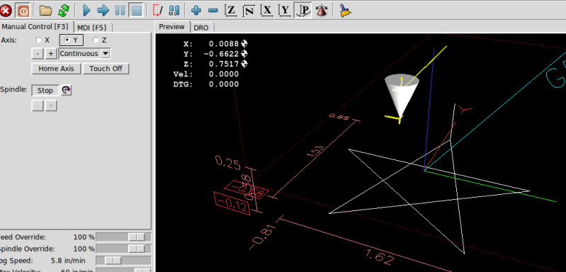
bianchi
I'm looking at your AXIS display and it looks like your Y axis is on the Y axis limit (the thin red line)
Do you use home switches? It seems not.
You must home to a consistent position regardless of if you use home switches or not.
The machine origin is calculated from the homeswitch location (not to be confused with home position) or in the case of no home switches it is calculated from the position you are at when you push home in the AXIS display. If (when not using home switches) you are not in the same location (or very close) each time you home the machine, your limits will not be right.
Do you home in the same location?
After homing you must set your user coordinates origin with touch off (in AXIS)
-
07-05-2012, 12:52 PM #9
Registered
- Join Date
- Apr 2012
- Posts
- 45
After doing some touch off
Finally I got like this :
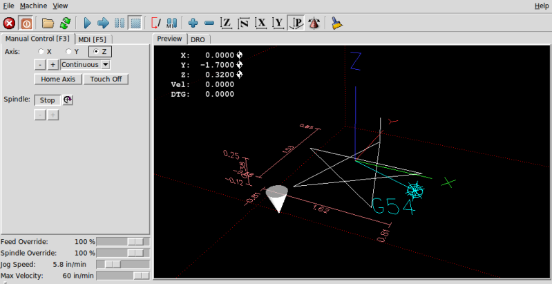
Am I doing the right thing ?
Thanks a lot
-
07-08-2012, 02:42 PM #10
Registered
- Join Date
- Apr 2012
- Posts
- 45
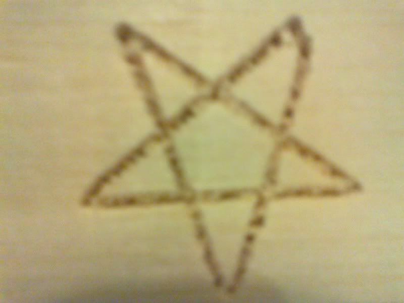
can engrave a simple star already,

 Reply With Quote
Similar Threads
-
DMG NEF600 CAM configure
By pentraks in forum Deckel, Maho, Aciera, Abene MillsReplies: 0Last Post: 06-10-2010, 07:19 AM -
Cannot configure the drive.
By LBodnar in forum CNC Machine Related ElectronicsReplies: 23Last Post: 01-27-2010, 02:49 AM -
Possible to configure without GD Tool?
By pixpop in forum CNC Machine Related ElectronicsReplies: 6Last Post: 12-22-2009, 06:13 PM -
configure new machine
By hanover owing in forum Mach MillReplies: 2Last Post: 12-03-2009, 10:18 PM -
How to configure.../ anything simplier?
By venomx999 in forum CNC (Mill / Lathe) Control Software (NC)Replies: 4Last Post: 07-30-2007, 12:59 PM
