


I have had my Novakon NM145 for about 18 months so suffered through using the original VFD with no low speed torque until Novakon sent a revised VFD. While much better than the original VFD the revised one hasn't been very reliable having failed twice already.
By failing I mean requiring repair or replacement not a quick power cycle or replacing the fuse. Even when keeping within the proper speeds & feeds it is possible to overload the VFD. The primary component on the VFD has a maximum rating of 10 AMPs continuous before it begins to overheat and fail. The good news is the component can monitor the current being used and prevent the failure. The bad news is that the controller doesn't seem to have the necessary circuitry to allow this to function.
I considered becoming a distributor for Sangmutan to be able to get a further revised VFD that may have addressed the problem. However, having had nothing but problems with the two versions of the VFD already I decided to look for an alternative.
Requirements:
- Be able to reach 6000 RPM
- Good low speed torque to be able to mill steel.
- Run on 120 or 230VAC, not 3 phase power.
- Good speed regulation.
- Rapid starting and stopping of spindle.
- Operate within the limits of the components selected.
- Use commercially available components available in days not weeks.
- Bolt on, not require significant modifications to the NM145
After some design and engineering I decided to use a 1-1/2HP 3600RPM 230volt 3phase AC induction motor and VFD powered by 120VAC single phase power. The motor can be operated at up to 5400 RPM by design so increasing the drive pulley by 15% gets the spindle speed up past the 6000 RPM desired.
Using Solidworks I designed an aluminum mounting fixture for the motor that replaces the original cast iron drive case and steel cover to reduce weight as much as possible since the AC motor is much heavier than the BLDC motor. The tough part was machining it on a bridgeport knee mill by hand since the NM145's VFD was dead.
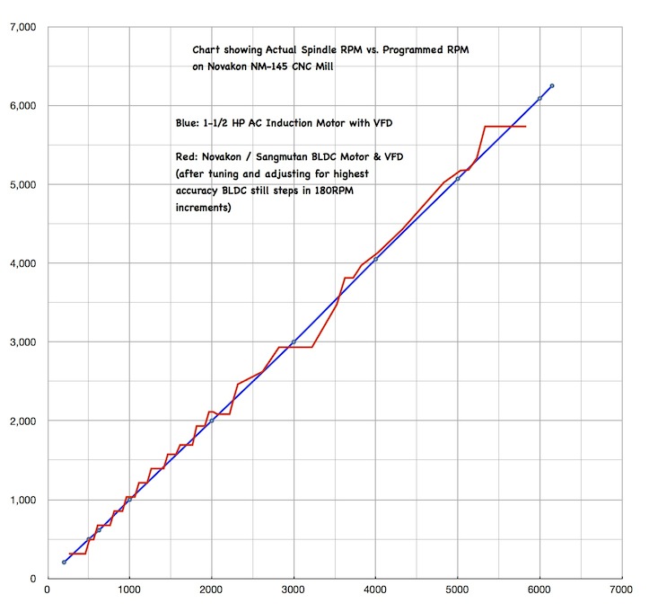
After getting everything assembled and wired I ran some tests. Speed and torque were good and after tweaking settings in Mach3, the VFD and break out board I was able to get near perfect speed regulation from 200 RPM to 6250 RPM. Below 600 RPM torque does drop off significantly but I designed for more RPMs so that was expected. I attached a copy of a chart I made showing the Novakon / Sangmutan RPM vs. programmed speed and the AC induction motor RPM vs. programmed speed. Huge difference, the odd 180RPM steps on the BLDC system were gone and the speed tracked almost perfectly without any weird offsets at low and high speed like the BLDC system.
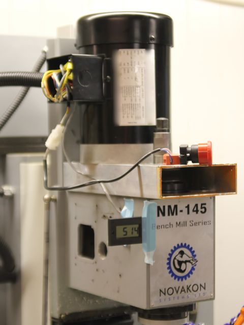
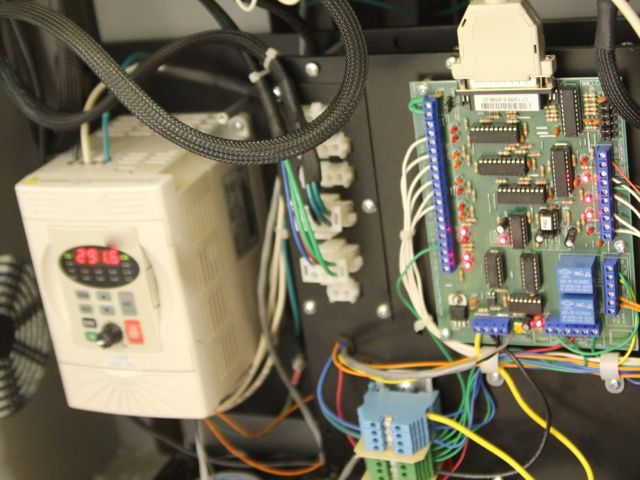
Also included are a couple photos showing the installation of the motor and VFD. The digital display taped to the NM145 is being evaluated as a way of displaying the load on the spindle / motor. Now that the NM-145 is back in operation I am going to machine a nicer mounting fixture that will mount the E-Stop button and load meter on the front face.
Charlie.
Results 1 to 10 of 10
-
07-25-2012, 03:17 AM #1
 Registered
- Join Date
- Jan 2011
- Posts
- 63
Alternative motor & VFD for the NM-145
Visit http://www.shadowspawnllc.com to see what enhancements I have available for the NM-145.
-
07-25-2012, 03:25 PM #2
Registered
- Join Date
- Oct 2011
- Posts
- 61
Which motor and VFD did you purchase Charlie?
-
07-25-2012, 09:44 PM #3
Registered
- Join Date
- Jul 2009
- Posts
- 96
I would defiantly like to see more. I ended up doing the same thing but the spindle speed is not under computer control. It looks like you are using the same vfd as me probably the same motor also. I just am not an electronics kinda guy I can do basic stuff and figure most things out but when I tried to figure out how to make the spindle speed interface with computer I was at a loss. Mostly because I am not intimately familiar with the novakon end of the system.
Are you using a braking resistor to make the spindle slow down faster than coasting?
-
07-26-2012, 03:56 PM #4
Registered
- Join Date
- Jan 2011
- Posts
- 63
The motor and VFD are both from Automation Direct. I have done many machine control / automation projects with equipment from Automation Direct and have used their VFDs often without any problems.
The VFD I selected from the GS2 series can be powered by 115VAC and still supply 4.2 amps at 230VAC 3ph. The motor is 3600 RPM 230VAC 3ph and draws 4.6 amps at full load. Why select a VFD whose spec's say it can't supply the current needed by the motor at full load? Simple. The VFD is the largest that can operate on 115VAC. Second the specifications are for continuous operation as in 24 hours a day, 7 days a week. The VFD spec also says it can supply 150% of max current for 1 minute which will address the occasional overloads encountered when pushing the machine too hard. Finally VFD control reduces current at both high and low RPM. In the end the motor performs like a 1.35HP motor that can easily handle any heat build up caused by low speed operation.
I have not installed a braking resistor yet. Instead I have the VFD programmed to do active braking limited by the current it can handle. With only the motor and spindle rotating there isn't that much inertia to deal with. At speeds 4000 RPM and under it stops in a fraction of a second. At full speed it takes about 1 second. Compare these times to the 20-30 seconds when the motor is allowed to coast to a stop on its own. With a braking resistor the times will be shortened to about 1/2 what it can already do.
Configuring the VFD, Mach3 and the breakout board to support control of both speed and turning on the spindle was a bit tricky. Getting the CNC4PC breakout board setup was the most difficult. It required connecting 12VDC power to it, connecting the analog output driven by pin 14 to the VFD then calibrating it after everything else was working. Mach3 had to be configured to drive pin 14 at the proper frequency, account for the pulley ratios, change the min and max RPMs and configure the spindle motor tuning. Compared to all the other configuration, setting the VFD up was quick and easy since I used several before.
What made it all possible was the documentation and wiring diagrams for the NM-145... the ones I painstakingly created when I traced almost every wire on the machine, noted the configuration of the CNC4PC BOB and documented every setting in Mach3.
I was thinking about machining up the mounting fixture and drive pulley then supplying them along with a list of items to buy (motor, VFD, etc.) and documentation / directions to allow someone with a non-functional NM-145 to get it back in to operation. (Did I mention how much fun it was machining the fixture on a manual bridgeport? Think about boring a 4.5" diameter hole, a couple 3.5" holes, 1.25" holes with a boring head then milling slots and cutouts...) If anyone is interested let me know.
Charlie.Visit http://www.shadowspawnllc.com to see what enhancements I have available for the NM-145.
-
07-26-2012, 04:06 PM #5
Registered
- Join Date
- Jul 2009
- Posts
- 96
I would be interested in the documentation and directions as I already have the motor mounted and the vfd motor combo. I just need to make the spindle respond to the computer.
 Another question comes to mind. do you see any electrical noise interference with everything being in the same case? My computer and everything is in there so I mounted the vfd outside and grounded the case case that houses the computer to act as a Faraday cage.
-
07-26-2012, 07:09 PM #6
Registered
- Join Date
- Jan 2011
- Posts
- 63
Yes, my monitor shows some electrical noise... just like it did with the revised BLDC controller Novakon supplied. In Novakon's infinite wisdom they choose to use ribbon cable as an extension to get the VGA signal to the outside of their cabinet. (My mill came with the computer pre-installed.) To make matters worse it is routed along side several other cables. I have a replacement shielded cable but I have yet to install it since it requires other components to be removed to route properly. Originally Posted by tjd10684

The noise is electrical not radiated so is present on the electrical power cables not broadcast like a radio. Using the cabinet as a faraday cage only protects from the radiated noise, the noise on the power wires will get in anyway.
What model of the Automation Direct VFD do you have? It makes a difference as to what is needed to configure and hook it up for external speed control.
Charlie.Visit http://www.shadowspawnllc.com to see what enhancements I have available for the NM-145.
-
07-27-2012, 07:41 PM #7
Company Representative

- Join Date
- Aug 2008
- Posts
- 400
We realize that while discussions are being presented on the zone between our existing and future customers, we would like to offer our research and observations to date for a more focused goal, based on customer inquiries from the past.
First and foremost we encourage and applaud the efforts that our customers that have put forth for the benefit of all to see and experiment in an open forum discussion. We are truly pleasantly surprised that our customers’ efforts have paralleled much of our work which gives us the opportunity to present our work as an alternative option with additional capabilities.
Our overall approach was to provide additional capability along with a better performing spindle motor. The approach we took was to install an AC servo motor with a commercial driver. Both units are heavy duty and designed for industrial use. The advantages we find with this approach, is the ability to perform rigid tapping seamlessly.
For your information the specs of the AC synchronous motor are:
• 1200W power (1.6 HP)
• 0 - 3000 RPM (0 - 4500 with step up pulley)
• 10000 steps per revolution encoder resolution
• Accuracy to within +/- 1 Hz
The motor, like in our associate’s project, had to be externally mounted due to the limited space within the head casting. As such, we designed and built a new motor mount casting that will fit on the NM-145. We have tried to minimize the number of parts to the ones illustrated in the attachments below. The result is a nice package that can be mounted with a few drilled/tapped holes.
The electronic package had to be reviewed as well in order to address the new servo driver. A new electronic chassis has been built to mount the driver and host some of the components from the previous controller. The heart of the tapping capability is the product of a new break out board (BOB), designed by Novakon, that performs function switching. The two functions are continuous rotation of the spindle motor and discrete control of the rotation similar to a rotary table. This BOB switching capability was facilitated in order to eliminate the software changes that would be required within Mach3.
The function switching is automatic within the BOB. The only decision that has to be made by the customer is if a 4th axis rotary table will be used or not. There is a single mechanical switch on the BOB to select the tapping function. When selecting the tapping function, the rotary table has to be disabled since the control of the servo is now under output “A” control from MACH3. This trade off seemed to be a reasonable compromise. Of course, the rotary table is still available for use if tapping is not desired.
The G-code for tapping is very easy and straightforward. This is due to the BOB controlling the switch between the continuous rotation and discreet control. The sophistication between the commercial servo driver and in conjunction with our BOB has removed the complexity of programming via G-code. The programming of the driver/MACH3 steps per revolution is set to easily program the number of spindle revolutions from G-code. As an example, if an operator was to use a ¼-10 tap and thread the tool one inch into the material, it is simply done by writing:
G 91
A 10, Z-1
A-10, Z 1
This will do a helical cut one inch into the work piece and then reverse helical travel out.
“Pecking” can be done as well by a variation of this program. An example of the “pecking” is shown in the video Novakon - YouTube. Shown in this video clip, we are tapping ¼” Aluminum plate with a 5/16-18 tap. We chose a pecking operation to illustrate the precision of the rotation of the spindle. The soft Aluminum can be tapped without pecking, especially if a 2-flute tap is used instead of the 4-flute tap as shown in the video. More video projects are in progress showing tapping of harder metals such as steel and also softer materials like machinable wax demonstrating the precision and preservation of the threads.
The spindle motor upgrade KIT is a direct result of the research and work done creating the Torus line of milling machines currently available in our website. This KIT is available on a pre-order basis by contacting [email protected].
We hope this article has helped our followers to better understand the work we are doing to improve the performance and reliability of our equipment.
Best regards,
The Novakon Team
-
07-27-2012, 10:36 PM #8
Registered
- Join Date
- Dec 2009
- Posts
- 594
I'm using a 220V input GS2 VFD from Automation Direct on my Bridgeport for the past 3+ years, and it has performed flawlessly.
-
07-30-2012, 02:58 PM #9
Registered
- Join Date
- Jan 2011
- Posts
- 63
Spindle Braking settings for Automation Direct GS1 / GS2 VFD drives
Much improved spindle acceleration / deceleration compared to the default settings on Automation Direct drives can be setup by programming the following parameters in the drive.
P1.00 Stop Method set to 00
P1.01 Acceleration Time 1 set somewhere between 1.0 to 2.0
P1.02 Deceleration Time 1 set somewhere between 1.0 to 2.0
On my NM-145 I have both Acc. and Dec. set to 1.0 seconds. On larger machines with heavier spindles a longer time may be needed. If a braking resistor is used the Dec. time can be even shorter.
Charlie.Visit http://www.shadowspawnllc.com to see what enhancements I have available for the NM-145.
-
08-02-2012, 07:38 PM #10
Registered
- Join Date
- Jul 2009
- Posts
- 96
I am using the GS2-22P0. I think its almost exactly the same except slightly beefer to run my 2hp motor.

 Reply With Quote
Similar Threads
-
Amphenol type motor connectors - cheap alternative pin-sockets.
By born2bewilder in forum CNC Machine Related ElectronicsReplies: 2Last Post: 02-19-2012, 10:10 PM -
UHMW alternative?
By theatrewizard in forum Linear and Rotary MotionReplies: 6Last Post: 10-15-2008, 02:19 PM -
PIC Alternative
By Lston in forum CNC Machine Related ElectronicsReplies: 3Last Post: 07-10-2006, 08:35 PM
