


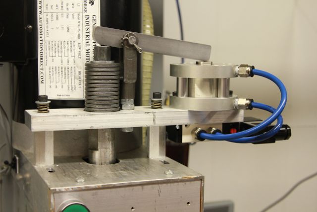
I have continue to enhance my NM-145 by adding a power draw bar. When used with 90 PSI of air pressure the mechanism can release a TTS collet held with just over 800 pounds of force. To preserve the life of the spindle bearings none of this force is applied to them. A stack of belleville springs is pinched by the mechanism. The stack of springs has a pre-load of 700-750 pounds this allows the draw bar to be manually released with a single turn of the draw bar nut. At the end of this post is a link to a movie of the PDB in operation.
Coming up next is a compact 8 position Automatic Tool Changer.
Charlie.
Here is a movie of it in operation.
[ame=http://www.youtube.com/watch?v=jtprjEO-etU]NM145-PDB - YouTube[/ame]
Thread: Power Draw Bar for NM-145
Results 1 to 18 of 18
-
09-08-2012, 09:17 PM #1
 Registered
- Join Date
- Jan 2011
- Posts
- 63
Power Draw Bar for NM-145
Visit http://www.shadowspawnllc.com to see what enhancements I have available for the NM-145.
-
09-09-2012, 03:05 AM #2
Registered
- Join Date
- Sep 2010
- Posts
- 72
Looks great Charlie!!
-
09-09-2012, 10:56 AM #3
Registered
- Join Date
- May 2011
- Posts
- 308
Wow! Thats awesome!
-
09-09-2012, 01:15 PM #4
Company Representative

- Join Date
- Aug 2008
- Posts
- 400
Fantastic job! Simple and effective...good engineering work.
How did you attach the pincher to the draw bar bolt? Did you make an extension piece or a new draw bar bolt? Do you have any rotational problem with wear? I would make one suggestion to possibly allow for more stroke for the QTC aperture opening. It may be a tight fit to locate the tool changer you are working on to the QTC opening.
Just something to consider. Again...great job!
Novakon
-
09-09-2012, 06:20 PM #5
Registered
- Join Date
- Jan 2011
- Posts
- 63
The key to the design is the drawbar / belleville / guide bushing assembly. The new drawbar is longer than the original. The drawbar and bellevilles are held centered with the bushing. The aluminum plate has a 1.25" hole through it to clear the 1.180" spindle. The spring washers are bigger than 1.25" so when the plate is lifted it pulls up on the washers while the lever pushes down. The springs holding the plate against the motor adapter cause the plate to always drop clear of the spring washers.
The photo and movie don't show it well but there is 0.050" clearance top and bottom when not energized. Nothing touches so there is no wear when running.
The TTS collet is driven downward about 0.100" already, it is loose in the spindle at that point. I have modified a TTS holder to make it self aligning so the tool changer will operate smoothly. Even when the TTS collet is completely out of the machine it still grips the TTS holder slightly so the tool changer is designed to pull the TTS holder not catch it when it falls out
The tool changer design is done. Will be significantly faster than the systems that rely on moving the z-axis up and down to drop and pick up tools.
Should have it running in two weeks since I have to order some material, a stepper motor, stepper driver, another breakout board, etc. I have already used up all the available outputs on the original machine.
Charlie.
 Originally Posted by Novakon
 Visit http://www.shadowspawnllc.com to see what enhancements I have available for the NM-145.
-
09-10-2012, 12:39 AM #6
Registered
- Join Date
- Jan 2010
- Posts
- 19
Nice job.
What are the air cylinder specs?
-
09-11-2012, 02:02 AM #7
Registered
- Join Date
- Jan 2011
- Posts
- 63
The air cylinder is a 2"bore with a 1" stroke available from Automation Direct for $65. The other components cost about $85 plus a bit for items and metal I already had on hand.
The length and ratio of the lever arm needs to be calculated based on the specifications of the belleville spring washers. I ended up with 24 washers stacked ()() I special ordered the washers along with the springs I needed for a hand injection molding machine I build to get beyond the minimum order requirements of my supplier. Choosing the spring washers is by far the most time consuming part of the design. Too many calculations had to be done against every spring washer, alloy and stack height combination to find the right one.
Charlie.Visit http://www.shadowspawnllc.com to see what enhancements I have available for the NM-145.
-
07-07-2013, 07:33 AM #8
Junior Member
- Join Date
- May 2013
- Posts
- 14
Hi looks good,
I I'm gathering information to build a power drawbar in the future, after I get through like 10 other project xD
I notice that your set up allows for 700-750 pounds but according to Tormach in order to avoid tool slipping you need
30 ft/Lb which translates to 2450 lbs of holding force is the 700-750 pounds you came up with enough force?
Best regards,
-JR
-
07-07-2013, 10:14 AM #9
Gold Member
- Join Date
- Feb 2006
- Posts
- 7063
I can tell you for a fact 750 pounds is enough for only very light milling - the kind even a lowly X2 mini-mill is capable of. To use the full capability of the NM145 would require at east 3X that, and the full capability of TTS requires more still - on the order of 3500 pounds drawbar tension, or 30 ft-lbs drawbar tightening torque.
Regards,
Ray L.
-
07-07-2013, 12:20 PM #10
Member
- Join Date
- Jun 2008
- Posts
- 1082
Tormach's own power draw bar has 2500 lbs. of holding force.
I can't wait to hear some more about the tool changer! Do you have any plans to distribute it in some way? Oh yeah, do you think it'll work with the Torus Pro?
-
07-07-2013, 02:24 PM #11
Gold Member
- Join Date
- Feb 2006
- Posts
- 7063
I did extensive testing a number of years ago, before I designed my first PDB for TTS, and found that is not enough for maximum retention on aggressive cuts. I've seen a number of comments from Tormach owners indicating that they do experience pull-out if they try to cut too aggressively. Hard to be sure they have their PDBs adjusted properly, but I know for a fact that at 30 ft-lbs, pull-out NEVER happens, even on the most aggressive cuts possible on both my 9x49 knee mill and my Torus Pro. On both machines I can stall the spindle, or snap off a 1/2" endmill, without inducing even the slightest pull-out. Originally Posted by Hirudin
Regards,
Ray L.
-
07-07-2013, 08:05 PM #12
Registered
- Join Date
- Jan 2011
- Posts
- 63
Ray,
The required tension in the draw bar varies depending on the horsepower of the spindle and the diameter of the shank in the collet plus the friction between the shank and collet. The NM-145 itself can only handle about 1HP applied to the cutter before it deflects beyond what a will produce a good finish. Based on the rigidity of the NM-145 and the available horsepower and range of spindle speeds the ideal end mill size is 3/8" diameter once all factors are considered. This is the size end mill I run almost exclusively unless a smaller diameter is needed for a feature. This is what I designed my PDB to handle with a bit of over capacity. To date I have not had a problem with a TTS adapter pulling out of the collet. I have however made sure my collet is smooth on the outside and cleaned up the mating surface in the spindle and applied some anti-sieze. These together greatly reduce the tension required since the tension is an indirect indicator of actual gripping force. Properly fitted surfaces with a perfect lubricant will allow the greatest compression on the shank.
The tension in he draw bar I have seen called out in several places all calculate the tension as if the drawbar is 7/16" in diameter when actually the minor diameter of the thread is only 0.3749. The 750 (actually 800 plus a bit) I designed for was compared to the 7/16" diameter. The actual tension in the threaded portion of the draw bar is closer to 1100 lbs per square inch.
Calculating tension based on torque applied is difficult due to various unknown factors. Referring to a reference chart for 7/16-20 torque requirements for Grade 2 with light oil (pretty much the grade of the steel the draw bar is made from) 36ft-lbs creates an ultimate clamp force of 4900 lbs. By changing only the oil used the torque required drops to 18 ft-lbs, only 50% vs "standard" oil. Bare metal (or light rust) the torque required increases to 48 ft-lbs. Therefore when someones tells me they need 30 ft/lbs of torque I have to wonder about the conditions of the machine, drawbar, collet, etc. since the actual draw bar force could be anywhere from 2000 lbs to over 6000.
For now I am going to stand by my decision to design for just over 800# of drawbar force since I took care to reduce the friction preventing the collet from compressing efficiently on the NM-145. Those people that have asked me about using my design on the NM-200 have heard I thought it did not produce enough clamp force since the spindle motor is larger and larger diameter cutters tend to be used. My design also causes the collet to eject at least 0.080", the minimum needed for the TTS collet I tested with to reliably release every TTS shank in my collection since some have a slight radius at the base instead of an undercut. I also wanted the PDB to NOT apply excessive force to the spindle bearings when ejecting to prevent divots in the races.
Your draw bar design obviously was targeted to the larger machines and meets the requirements of those machines. In the case of the NM-145 the requirements are more modest so the design different.
Charlie.
Originally Posted by SCzEngrgGroup
Visit http://www.shadowspawnllc.com to see what enhancements I have available for the NM-145.
-
07-08-2013, 01:47 AM #13
Registered
- Join Date
- Feb 2010
- Posts
- 371
Nicely done Charlie.
I went with 2500lbs tension on my NM-145. I found that if you get any high pitch squeel, it can greatly effect the holding power of the TTS.
-
07-08-2013, 02:12 AM #14
Member
- Join Date
- Jun 2008
- Posts
- 1082
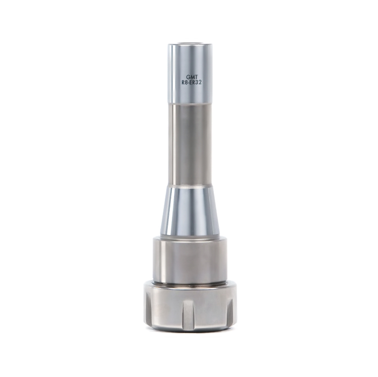
The one time I had pullout with my draw bar actuator (with 2800 lbs. of holding force) the end mill was squealing pretty badly as well. The only other time I've knowingly had pullout is with a 3/8" end mill in a Glacern R8 ER-32 collet holder. It was also vibrating/squealing pretty badly. I thought the squealing was basically "normal" for a machine this size and actually kept a pair of earmuffs handy so I could wear them whenever it got too bad.
I have the Glacern incident on video, maybe I'll put it on YouTube some time...
(attached is a screenshot of it cutting into my vise when it go too low)
-
07-08-2013, 02:49 PM #15
Registered
- Join Date
- Mar 2009
- Posts
- 163
Can you describe the bushings? Seems to me the key to success here is getting good sliding on the bushings despite having offset forces
-
07-09-2013, 03:46 AM #16
Registered
- Join Date
- Feb 2010
- Posts
- 371
Ouch! I can see the gap between the spindle and the collet. Cool picture though. Originally Posted by Hirudin
-
07-09-2013, 05:20 AM #17
Member
- Join Date
- Jun 2008
- Posts
- 1082
Ouch indeed! It didn't make me very happy... :/
The gap that's visible is actually normal since it's an R8 shanked collet holder. The pullout actually happened between the bit and the ER-32 collet.
-
07-17-2014, 08:21 AM #18
Registered
- Join Date
- Apr 2011
- Posts
- 8
Re: Power Draw Bar for NM-145
Do you have any other pictures of it that you could share?

 Reply With Quote
Similar Threads
-
My X3 Power Draw Bar!
By ImagineRobots in forum X3/SX3/G0619/G0463Replies: 39Last Post: 09-23-2015, 05:29 AM -
Power Draw Bar
By nitewatchman in forum Tormach Personal CNC MillReplies: 3Last Post: 11-06-2012, 02:33 PM -
Power Draw Bar
By Blakea1790 in forum Tormach Personal CNC MillReplies: 25Last Post: 11-10-2011, 09:56 PM -
Power Draw for 7.5hp VFD
By Southbend Sam in forum Phase ConvertersReplies: 4Last Post: 04-25-2011, 08:43 PM -
Power Draw Bar for 770
By oknups in forum Tormach Personal CNC MillReplies: 3Last Post: 01-27-2011, 02:05 AM
