


Hey guys. I hate to keep using you geniuses and hitting-and-running for advice so let me say that I have indeed used the search button prior to posting.
I last posted about a wire gauge question for powering a home Bridgeport. Well, I ended up buying a new bike and sort of forgot about the Bridgeport all summer. It got cold quickly so I'm stuck in the garage again.
I ended up crunching numbers based off a welder (max amperage I would ever draw at once) and ran 8/3, some conduit, all the way to my breaker. I plan on adding a sub panel out in the garage but for now the Bridgeport is all that would be on this line.
I bought a Hitachi WJ200-SF015.
I wired it up, it turns on, fantastic. (Haven't wired it to the Bridgeport yet)
Why the Hitachi VFD? I plan on expanding to a CNC machine and wanted precise control. For now it's just an old round ram Bridgeport.
So like I said, I did use the search and I did read. I found out I have to bypass the drum switch and run the VFD straight to the motor. From there I should be able to control forward and reverse.
Now my issue is what do I do about the power feed? I looked at a few models of Bridgeports before purchasing this one. I chose this one for it's factory power feed.
Stock wiring goes into a junction box and splits off to the power feed and to the drum switch. I've only removed the wires from the drum switch so far.
I can't help but feel I should've bought a rotary instead of the VFD. Most of what I've read so far is about hooking up the Bridgeport motor. I haven't seen anything about the power feed.
I'm also concerned with power tapping. From what I've seen of other people's Bridgeports with VFD's I won't be able to start, stop, and reverse while power tapping.
Questions, comments, laugh at me?
Thread: Wiring Hitachi VFD to a Bpt
Results 1 to 19 of 19
-
10-17-2012, 02:24 PM #1
 Registered
- Join Date
- Jan 2008
- Posts
- 60
Wiring Hitachi VFD to a Bpt
-
10-17-2012, 03:25 PM #2
Community Moderator
- Join Date
- Dec 2003
- Posts
- 24223
First you get rid of the drum switch, ideally you would fit a power relay or contactor in place of the drum switch and the 240v VFD feed pair would be fed from the relay, this would be picked up by the E_stop circuit.
The stop start is by contact closure to the VFD inputs.
Al.CNC, Mechatronics Integration and Custom Machine Design
“Logic will get you from A to B. Imagination will take you everywhere.”
Albert E.
-
10-17-2012, 03:59 PM #3
Gold Member
- Join Date
- Jan 2006
- Posts
- 2985
I would think the drum switch is triple pole, double throw. That should allow you to use the drum switch for forward/stop/reverse inputs to the VFD I would think. A separate E-stop switch would still be needed.
I would think the power feed is single phase? In that case, it should be trivial to connect. If it is 3 phase, you would need another VFD for it.
Matt
-
10-17-2012, 05:03 PM #4
Community Moderator
- Join Date
- Dec 2003
- Posts
- 24223
I don't think you will regret using a VFD over an RPC.
Also on many BP's the power feed was 1ph fed DC drives and motor.
Al.CNC, Mechatronics Integration and Custom Machine Design
“Logic will get you from A to B. Imagination will take you everywhere.”
Albert E.
-
10-17-2012, 05:31 PM #5
Registered
- Join Date
- Jan 2008
- Posts
- 60
I should've included more details...
I am feeding, to the garage, 240VAC 1ph from my main panel.
This goes directly to the VFD until I can afford a sub panel.
The bridgeport itself has a 240VAC 3ph motor on the top. I am uncertain about the power feed but I can say that the power input to the Bridgeport goes to a junction box and then two outputs leave the junction box. One output goes to the power feed; whether or not it's only one hot lead becoming 110 I do not know. (I'll blow the junction box cover and investigate this tonight)
The second output goes to the drum switch and then to the motor.
I'd really love to keep the VFD mounted on the wall and strictly control the Bridgeport through the drum switch but everything I've read says wire the VFD directly to the motor bypassing the drum switch entirely.
I called the cat at Drives Warehouse to make sure I had it wired properly. Hot in L1, hot in L3, no neutral (wire nut to terminate), and grounded to the chassis of the VFD.
I haven't hooked any outputs to the VFD yet but while energized I put an ohm-meter on the outputs for the VFD and I wasn't seeing any voltage out at all.
That's when I figured I'd check the manual again but started thinking about the power feed and posted here.
-
10-17-2012, 05:36 PM #6
Registered
- Join Date
- Sep 2012
- Posts
- 7
Steve -
I have you covered on that, I'll try to get over there soon....
 Originally Posted by Paraquat

-
10-17-2012, 06:23 PM #7
Gold Member
- Join Date
- Jan 2006
- Posts
- 2985
As Al said an E-stop circuit would be recommended to safely kill power to the machine. I'd say at a minimum you should buy a small disconnect to mount on the wall. That would allow you to shut it off safely in the garage without having to run to your basement while the sparks are flying.
You cannot have a switch between the VFD and the motor, as you already know. I am recommending using the drum switch for the CONTROL section of the VFD. The drum switch would tell the VFD how to control the motor.
There should be 3 hots and a ground for your motor. There are probably 2 hots and a ground or 2 hots, a neutral and a ground to your power feed.
The VFD will only control the spindle. If the power feed is single phase, you can run it directly from your single phase supply, connected in the same place as your VFD.
I think a schematic would help to get things sorted out.
Matt
-
10-17-2012, 07:15 PM #8
Registered
- Join Date
- Jan 2008
- Posts
- 60
Clint? Is that you? You're on this forum too? Originally Posted by cdm_ct
Bullett came over and we ran the power line last weekend.
Yes, there are two hots and I wired the white and ground to the grounding strips in my main panel.
A schematic would be greatly appreciated if you could provide one. It's been a solid decade since I've done anything with AC that I couldn't do with an extension cord.
-
10-17-2012, 07:42 PM #9
Community Moderator
- Join Date
- Dec 2003
- Posts
- 24223
If the white you refer to is the neutral, that is a NO-NO. Originally Posted by Paraquat
The neutral should be connected to the earth ground at the Panel or service entry point ONLY.
Al.CNC, Mechatronics Integration and Custom Machine Design
“Logic will get you from A to B. Imagination will take you everywhere.”
Albert E.
-
10-17-2012, 09:49 PM #10
Gold Member
- Join Date
- Jan 2006
- Posts
- 2985
Here is a shiddy paint version for discussion.
I made some of the stuff up since I don't know what you have but it should be close to this. The contacts for the VFD control could possibly come from your drum switch so it would be controlled just like a manual machine. You'd have to look into the instant reversing though.
You can get most of the parts to make this happen from The best way to buy industrial controls--low prices, fast shipping and superior service.
I have found they have good pricing on industrial controls.
Matt
-
10-17-2012, 09:51 PM #11
Gold Member
- Join Date
- Jan 2006
- Posts
- 2985
Al Originally Posted by Al_The_Man
I took main panel to mean his service entrance, in which case he should connect the ground and neutral to the bars in the main breaker panel, which will be connected together, as you know.
Matt
-
10-18-2012, 01:44 PM #12
Registered
- Join Date
- Sep 2012
- Posts
- 7
Yup... Originally Posted by Paraquat
I see one of the guys posted a schematic for you...
I had an much older account on here, but it got canned i think.
-
10-18-2012, 11:19 PM #13
Registered
- Join Date
- Jan 2008
- Posts
- 60
You've got a lot more going on in your drawing than I do.
Allow me to dumb it down even more for me.
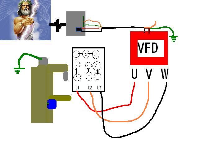
I cracked open the junction box.
Inside is a red wire going to a pair of green wires: one to the motor, one to the power feed.
Next is a white, all wired tied together going to the motor and to the powerfeed.
Next is the black wire which goes to the motor and the power feed.
Lastly the ground is screwed in the back of the junction box.
As if the wiring didn't prove it I examined the data tag on the motor to confirm it. It is indeed 220VAC 3Ph.
And yes, at my entry point (what I referred to as main panel) I have two grounding strips. I attached the white and the ground to those.
I've attached my crude version of a cartoon illustrating how far I've gotten. U, V, and W are the outputs listed in the Hitachi manual.
-
11-03-2012, 01:26 AM #14
Registered
- Join Date
- Jan 2008
- Posts
- 60
I've got this now.
I hit run and nothing happens.
I went into F01 (output freq setting) and changed it from 50 to 60hz.
I go to d01 (output freq monitor) and get 60.
I go to d08 (actual output freq) and get 0
I go to d013 (output voltage monitor) and get 2.4
I have continuity between the Bpt and the chassis ground.
I have 120 each leg of the input to ground. I have 220 between the two inputs.
If I select "RUN" and choose EITHER U, V, or W to the gnd I get 119.6-120.2 each leg.
If I measure any two legs I get a fluctuation between 8-18 volts.
Where did my 3rd phase go?
Extra credit: http://www.practicalmachinist.com/vb...switch-242339/
Found this guy's post for using the drum switch.
-
11-03-2012, 01:42 AM #15
Registered
- Join Date
- Sep 2012
- Posts
- 7
Just remembered, some digital meters can't get a stable reading... Off the vfd output. What meter u using....
Sent from my PC36100
-
11-03-2012, 01:58 AM #16
Gold Member
- Join Date
- Sep 2012
- Posts
- 1543
Turn on "Min Max" if you have it on your meter
-
11-05-2012, 04:34 PM #17
Gold Member
- Join Date
- Jan 2006
- Posts
- 2985
I think you might need to do some more reading in your VFD manual.
Actual output frequency of 0 would mean the VFD has the motor stopped. What are you using for a speed reference? Internal command or what? It seems to me that it is not going because it is being commanded to go 0 hertz, that would be an energized, stopped motor. The voltage to ground does not run the motor. You should be checking voltages phase to phase. U-V U-W V-W
Matt
-
11-05-2012, 05:07 PM #18
Community Moderator
- Join Date
- Dec 2003
- Posts
- 24223
Generally these drives will run in some fashion right out of the box, did you go through the initial test and set up in Ch.2 using the pot on the front?
Al.CNC, Mechatronics Integration and Custom Machine Design
“Logic will get you from A to B. Imagination will take you everywhere.”
Albert E.
-
11-05-2012, 06:20 PM #19
Registered
- Join Date
- Jan 2008
- Posts
- 60
That's where I was getting the 8-18 volts leg to leg. Originally Posted by keebler303
Turns out I had a few screw ups. The switch for fwd/rev was shorted internally and the pot. I had was out of range. Clint called it during a phone conversation we had. Originally Posted by Al_The_Man
I swapped out the pot and just removed my fwd/rev switch from the equation. I was able to get the motor fired up last night. I'll deal with the power feed another time but for now it's up and running.
First project on the docket is a mounting bracket for the switch and enclosure for the VFD.
Thanks for the help guys.

 Reply With Quote
Similar Threads
-
Hitachi VFD in Aus?
By rnm85 in forum Australia, New Zealand Club HouseReplies: 4Last Post: 08-15-2014, 05:52 PM -
Hitachi L200 Intelligent Input Terminal wiring
By robhrzic in forum Phase ConvertersReplies: 25Last Post: 04-05-2012, 04:20 AM -
Hitachi 810 Q
By Stiga in forum EDM Discussion General TopicsReplies: 0Last Post: 11-07-2010, 12:47 AM -
Hitachi MS 250
By Stiga in forum EDM Discussion General TopicsReplies: 0Last Post: 11-06-2010, 08:52 PM -
Hitachi 6M
By Spinner in forum Plasma, EDM / Other similar machine Project LogReplies: 0Last Post: 07-06-2007, 07:21 PM
