


Hi
I have a really nice maxon brushless DC motor that I want to use as a low power but high power density spindle. So I started designing a spindle and relised I needed to use angular contact ball bearings. However I had no idea how to mount them so I looked around on the skf website and this forum and got more and more confused. Then I had a eureka moment. I have already bought some chinese c7 ball screws with fixed end supports, I thought, I'll just pull them apart and see how they are done, which I did. But when I did I found the bearings inside did not look like angular contacts at all, just plane old deep groove ball bearings. I can't be sure as I have not taken the metal covers of each side of each bearing but the inner races look to be the same diameter both sides with the covers on.
Is this normal for cheap Chinese ball screw mounts or are these particularly bad ones?
Also how can I mount the ER11 collet chuck I have between two 7202 or similar angular contact bearings? I've modeled this up in solidworks but I have no idea if it will work or preload the bearings correctly.
llet
Thread: Angular Contact Bearings
Results 1 to 20 of 30
-
10-24-2012, 11:46 AM #1
 Registered
- Join Date
- Jul 2012
- Posts
- 0
 Angular Contact Bearings
-
10-24-2012, 02:12 PM #2
Member
- Join Date
- Jan 2005
- Posts
- 15362
Anita
Here is a bulld that I did that will help you with what you want to do, you can make some changes to this design, but the basic principles can not change very much, for a successful spindle build
http://www.cnczone.com/forums/cnc_wo...dle_build.htmlMactec54
-
10-24-2012, 02:41 PM #3
Registered
- Join Date
- Mar 2004
- Posts
- 1306
As far as I can tell, widely separated bearings like you draw lead to issues with the thermal expansion. The design tolerances seem to get pretty tiny, and thus differcult to us hobby guys to control.
I copied the bearing arrangement from Herbertkabi, as back to back bearings at the nose seemed easy to do.
CNCzone.com-The Largest Machinist Community on the net! - Powered by vBulletin
Here is my version. It has been sitting in a box waiting for the machine to get finished.
http://www.cnczone.com/forums/vertic...pindles-2.htmlRegards,
Mark
-
10-24-2012, 02:47 PM #4
Registered
- Join Date
- Oct 2005
- Posts
- 328
I'd say it won't work as drawn. You have nothing preloading the bearings at all. To use them as they are drawn, you need to have something forcing outer races of the bearings toward one another, applying the preload to the bearings. It may be easier to flip the bearings and use threads and a nut on the spindle to force the inner races toward one another. This leaves the outer races being kept apart by the outer body. Hope that makes sense. I don't have an easy way to demonstrate that on my work computer.
Dave
-
10-24-2012, 02:52 PM #5
Registered
- Join Date
- Dec 2011
- Posts
- 161
Look at this, you can see he's mounting the bearings in the spindle shaft, and then compressing the shaft to the spindle body using the black nuts in the top of the assembly.
I have no other way to show you this right now but maybe you get an brief idea of what we're trying to say.
http://www.cnczone.com/forums/vertic...nc_mill-5.html
-
10-24-2012, 03:02 PM #6
Registered
- Join Date
- Oct 2005
- Posts
- 328
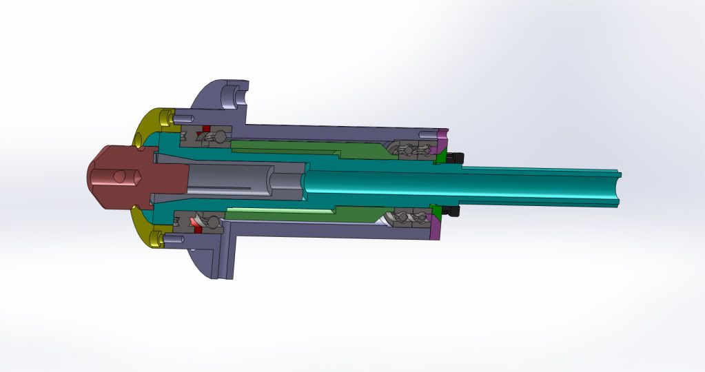
Here's a good cutaway from that thread of what he seems to have done. Originally Posted by leix_99

-
10-24-2012, 03:07 PM #7
Registered
- Join Date
- Dec 2011
- Posts
- 161
That's it Whateg, i think te ones in the bottom are AC, with some sort of preload (or simply a spacer?) and the ones in the top just regular bearings. That spindle is soooooo lovely

-
10-24-2012, 05:17 PM #8
Registered
- Join Date
- Mar 2004
- Posts
- 1306
Herbert Kabi's design, preloads the whole stack (dual nose bearings with a shim, long spacer and the upper bearing inner race with a nut or fastener at the top of the shaft.
Both the lower bearing pair, and the upper bearing then need a something to lock and locate the outer races.
Here is a the cross section of my spindle:
http://www.cnczone.com/forums/attach...2&d=1272137748Regards,
Mark
-
10-24-2012, 07:50 PM #9
Registered
- Join Date
- Jul 2012
- Posts
- 0
Wow, thanks guys! I just went to bed and when I woke up there where 7 new posts! I've read through the links and I think I will go with just two angular contacts at the bottom of the spindle and one deep grove at the top. However I can buy a Chinese spindle for about 300NZD on aliexpress (including the motor) so I'm trying to keep under that budget. Considering I have the motor and controller already and access to a state of the art machine shop for free, it should be easy... maybe. But I need to find some good quality cheapish angular contact bearings. First I bought 50 little deep grove ball bearings on Ebay which looked too weak when I got them (sunk cost $25 inc shipping) then I bought 2x 7202 angular contacts also on ebay (cheap as ones about $5 each and probably imported from china to the UK where the seller was total sunk cost another $25) but they have about 0.5mm or so of play (unmounted) so I think their rubbish.. don't know for sure because their unmounted. Are angular contacts supposed to have that much play before they are mounted?
I found these this morning 7202 Nachi Angular Contact Bearing Steel Cage C3 Japan 15x35x11 Ball Bearings, what do you think? Also did anyone have any thoughts on my first question? Should I throw my Chinese ball screw bearing mounts away?
-
10-24-2012, 07:54 PM #10
Registered
- Join Date
- Jul 2012
- Posts
- 0
I saw the drawing you attached thanks! But is the shim between the angular contacts between the inner or the outer races? Also do you have any details on the valve spring? Originally Posted by RotarySMP
-
10-24-2012, 07:58 PM #11
Registered
- Join Date
- Jul 2012
- Posts
- 0
could you please post a link to the Herbertkabi arrangement you mention? Originally Posted by RotarySMP
-
10-24-2012, 08:00 PM #12
Member
- Join Date
- Jan 2005
- Posts
- 15362
whateg01
This design you have, a nice drawing of, would not run very well if it was made like this
This is not how you make a spindle, for anythingMactec54
-
10-24-2012, 08:06 PM #13
Registered
- Join Date
- Jul 2012
- Posts
- 0
while this is extremely impressive it's a little more than I want to get into just yet, I'm just mounting one small ER collet chuck directly in bearings (with no ER or R8 collet chuck changing function). The machine is only desgined to take light cuts, here is a screen shot of where I'm up to so far Originally Posted by whateg01

-
10-24-2012, 08:10 PM #14
Registered
- Join Date
- Jul 2012
- Posts
- 0
Thank you for the positive encouragement mactec.. I realise that it would not work, I'm just trying to explain what I want to do and where I'm up to with the design which is not far on the spindle - although I'm a little further through with the rest of the design as you can see in my last post. I have no idea how a spindle should be done so any more help would be greatly appreciated. Originally Posted by mactec54
Thanks
-
10-24-2012, 08:39 PM #15
Registered
- Join Date
- Oct 2005
- Posts
- 328
It's not mine. I just copied the link from the thread that was referenced. Originally Posted by mactec54
Dave
-
10-24-2012, 08:51 PM #16
Member
- Join Date
- Jan 2005
- Posts
- 15362
Anita
I was not referring to your drawing, yours was obvious just an idea
If you read my thread you will see how to best put a simple ER spindle together
I have other designs as well that may be more suited to what you want to do, & are easier to build & cost less as well
I would need to know what materials you want to machine & the max size cutters you will useMactec54
-
10-25-2012, 12:55 AM #17
Registered
- Join Date
- Jul 2012
- Posts
- 0
Thanks yes, I will have more of a look through your thread tonight. At a first glance this morning it was hard to understand the whole assembly. I will have a better look tonight. You have certainly made a stunning job of that spindle. I think if mine comes out half as good I would be well pleased. Originally Posted by mactec54
I'm mainly looking to cut aluminium, plastic and wood. It's very challenging because you really need coolant for Al and plastic but you can't use it for wood. It means I can't have a continuous lube feed to the ways.. But I've nearly got that part of the exercise sorted. Point is these are the materials I want to cut with the spindle. Maybe the odd very light cut in steel but this will be first and foremost a prototyping desk top machine for these light materials only.
-
10-25-2012, 01:54 AM #18
Member
- Join Date
- Jan 2005
- Posts
- 15362
Anita
This is not much of a drawing but will make the spindle in the thread a little easyer to see how that one went togetherMactec54
-
10-25-2012, 12:30 PM #19
Registered
- Join Date
- Jul 2012
- Posts
- 0
thanks for the drawing! from that and the photos in your thread i came up with this but i dont know how to have the bearings or about the spring.. Originally Posted by mactec54

-
10-25-2012, 12:47 PM #20
Registered
- Join Date
- Jul 2012
- Posts
- 0
must be more like this with preload applied by nut holding pulley on, there also has to be a shoulder at the bottom of the chuck


 Reply With Quote
Similar Threads
-
angular contact bearings ( 8mm id )
By veteq in forum Linear and Rotary MotionReplies: 5Last Post: 08-18-2014, 09:32 PM -
angular contact bearings, or not
By klick0 in forum Linear and Rotary MotionReplies: 23Last Post: 04-12-2012, 04:49 AM -
Angular contact ball bearings
By Yovav in forum Mechanical Calculations/Engineering DesignReplies: 5Last Post: 08-08-2009, 03:27 AM -
why angular contact bearings for X3?
By lagfish in forum Benchtop MachinesReplies: 6Last Post: 01-09-2008, 12:12 AM -
Angular contact bearings
By martinw in forum Mechanical Calculations/Engineering DesignReplies: 38Last Post: 12-26-2006, 01:35 PM
