


I want to start switching low power 110V peristaltic pumps, small 150 watt heaters and some more common devices for may reef tank. I would like to know what shield or boards would work best for my application, in your opinion.
Aduino Mega 2560 is the controller. On that is stacked a stepper motor driver shield and an LCD display shield is on top of that. I have second type of motor driver that is not stacked.
Stacking would be good for this board but that real estate is pretty crowded so the board could be off to the side, connected via wires and connector(s). I use CAD software and a friend has a RepRap machine which will allow me to construct a custom enclosure so I don't use a bread board.
Many of the pin addresses are already used and I don't think that I can change some of them so I need a relay board that allows me to use some of the many pins that I have left over on the Mega.
Looking around the net, there are several things that might work but I don't have enough knowledge to make a good decision. What do you think would work for me?
Results 1 to 7 of 7
-
11-03-2012, 12:49 AM #1
 Registered
- Join Date
- Apr 2011
- Posts
- 73
Choosing 110V Relays for Mega 2560
-
11-04-2012, 06:09 AM #2
Registered
- Join Date
- Apr 2011
- Posts
- 73
16-Channel 5V Relay Module. For PIC ARM AVR DSP Arduino MSP430 TTL Logic SainSmart
Would this work? How would I hook it up? What I just pin a pair of pins on the arduino for each channel and hook it to the relay board?
-
11-04-2012, 01:31 PM #3
Gold Member
- Join Date
- Jan 2010
- Posts
- 2141
Your link goes to a board that requires 12 volts to actuate each relay.
The Arduino runs off of 5 volts (and has a maximum input voltage of 5 volts on the digital i/o pins).
So you will need a 12 volt power supply and one transistor, one diode, and one resistor for each relay that you will want to drive.
See either or both of the following for info on hooking it up:
Connecting a 12V relay to Arduino
http://www.arduino.cc/playground/upl...ain/relays.pdf
You may be able to find other boards that use solid state relays (SSRs) that could run directly from the Arduino interface and power supply.
-
11-04-2012, 05:37 PM #4
Registered
- Join Date
- Apr 2011
- Posts
- 73
How about this?
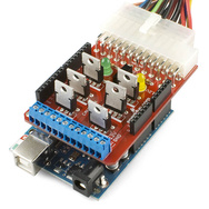
(Actually a picture of the DEV-10305, replaced by DEV-10618 noted below.)
https://www.sparkfun.com/products/10618?
If so, I understand that I would have to double-up on the stackable headers to clear the MOSFETs.
What is that big long blue connector in the foreground or to the left near the 5V input? It looks like where you connect the outgoing AC power lines with screw terminals.
What is that Pins for the translucent white multi-pin connector with the multi colored wires coming out of it, at the other end or on the right.
Again, would I simply choose the pins that I want to use and assign them? Then, put in the 110V wires into the screw terminals?
-
11-04-2012, 11:52 PM #5
Gold Member
- Join Date
- Jan 2010
- Posts
- 2141
I don't think that board will do what you want. Originally Posted by herring_fish

It appears to be set up to switch high-current DC loads at low voltage, whereas I believe that you want to switch higher-voltage AC loads drawing moderate amounts of current.
The white connector on one end of the board is for hooking up an ATX power supply designed for use in a PC (which is intended to provide the power for the high-power loads (half of the board uses 12 volts from the ATX supply and the other half uses 5 volts from the ATX supply).
The blue connectors are where you would wire up the DC loads to be switched (along with the power to those loads).
-
11-05-2012, 04:19 PM #6
Registered
- Join Date
- Apr 2011
- Posts
- 73

For better or worse, I bought the following:
SainSmart 8-Channel 5V Solid State Relay Module Board for Arduino Uno Duemilanove MEGA2560 MEGA1280 ARM DSP PIC
[ame=http://www.amazon.com/gp/product/B006J4G45G/ref=oh_details_o00_s00_i00]Amazon.com: SainSmart 8-Channel 5V Solid State Relay Module Board for Arduino Uno Duemilanove MEGA2560 MEGA1280 ARM DSP PIC: Computers & Accessories[/ame]
I hope that this will work for me. Thankyou all for the help.
-
11-05-2012, 05:10 PM #7
Gold Member
- Join Date
- Jan 2010
- Posts
- 2141
That board should do exactly what you want.

 Reply With Quote
Similar Threads
-
I'm about to buy a replacement Arduino Mega 2560
By herring_fish in forum Hobby DiscussionReplies: 0Last Post: 12-22-2011, 03:20 AM -
Arduino Mega driving my cnc.
By aventgps in forum VideosReplies: 2Last Post: 12-30-2009, 08:57 AM -
2560 error
By guydrisc in forum OkumaReplies: 2Last Post: 05-11-2009, 03:01 PM -
OpenCascade CAD for Windows - Mega Problems
By WayneHill in forum CodingReplies: 8Last Post: 11-17-2006, 09:10 AM -
surplus mega place
By Cyclone in forum DIY CNC Router Table MachinesReplies: 4Last Post: 06-15-2005, 10:32 AM
