


I would love to see this new rail system. Got any pics or drawings?Originally Posted by RNation0001

Also, seems your machine uses light weight extrusion. You may want to look at the heavy weight version of the same profile, especially for the bridge. It's rock solid, more expensive and heavy as hell and what I will be using in my next build.
I saw some on ebay in 1.5" X 3" for .90 (cents)/inch, perfect for a bridge if doubled to 6".
Results 21 to 40 of 74
-
11-22-2012, 05:02 PM #21
 Registered
- Join Date
- Aug 2008
- Posts
- 54
-
11-22-2012, 05:38 PM #22
Registered
- Join Date
- Nov 2012
- Posts
- 59
Don't have any pics yet but its a PRoven design that looks promising. Yea when I ordered it I went with the heavy 80/20. Uprights are 1545 series ( 1.5" x 4.5" ) and the gantry horizontal is a 3030 piece ( 3" x 3" ) and I'm gonna put brackets everywhere. That and the piece of steel plate should also help keep it rigid. Ill try to get a drawing up asap Originally Posted by jsearles
-
11-22-2012, 06:14 PM #23
Member
- Join Date
- May 2012
- Posts
- 231
Try here there are more in this area of Ebay
2 x25MM FULLY SBR25-3500mm SUPPORTED LINEAR RAIL SHAFT& 4SBR25UU Rounter Bearing | eBay
or here
http://www.ebay.com/itm/2-Set-SBR20-...item3ccc81b09c
-
11-23-2012, 02:06 PM #24
Gold Member
- Join Date
- Apr 2009
- Posts
- 5516
While one can learn building an "omperfect" machine, I think the goal here is to stress the importance of ridgidity, expecially in a machine intended to machine soft metals. With supported round rails as easily available as the unsupported type, it would seem indefensible to me to encourage someone to continue along a path that has all but proven to be inefficient and unsarisfactory to man y who have built or bouught a machine with similar features. There are many threads here as well as the other forums on just this topic. Originally Posted by jsearles
If you've followed any thread here that discusses the routing of aluminum, you'll see that higher speeds are needed with the higher RPM spindles normally used in DIY machines, namely wood routers. Since the feedrate is directly proportional to the spindle speed to achieve the "proper" chiploads, it's obvious to me that we'd need to build a machine, even a first one, to at least a minimum of ridgidity so the machine can withstand the forces at the higher feedrates needed. You cannot just say that you can cut parts slower, because that would also necessitate a spindle that can spin slower with enough torque, and that is not normally the case with wood routers. Bits and endmills are expensive to begin with, and they're more expensive when the learning process involves tool breakage and down time.
In fact our words here are not to discourage the OP from building a machine but to encourage him to find a "better" solution, which he seems to be doing. It doesn't take much effort to use better components. As to the comment of mot seeking "perfection" or "precision" with a first machine, why then buy precision ground and hardened linear rod then?
-
11-23-2012, 05:48 PM #25
Registered
- Join Date
- Nov 2012
- Posts
- 59
Originally Posted by louieatienza
ur like the yoda of cnczone lol. sounds like u know ur stuff, ok what do yall think about this, supported shafts are stupid expensive, and cutting them with my machine before some support is out of the question i guess, but what if i took the end supports and modified them to do the job i need?
it would look like this
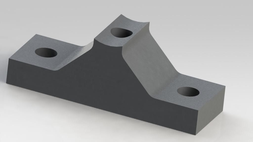
and with the hole in the center i can go all the way thru the table then also screw down the sides of the supports to keep from side to side flex, may not be perfect but looks promising to me at least lol
-
11-23-2012, 06:32 PM #26
Registered
- Join Date
- Nov 2012
- Posts
- 59
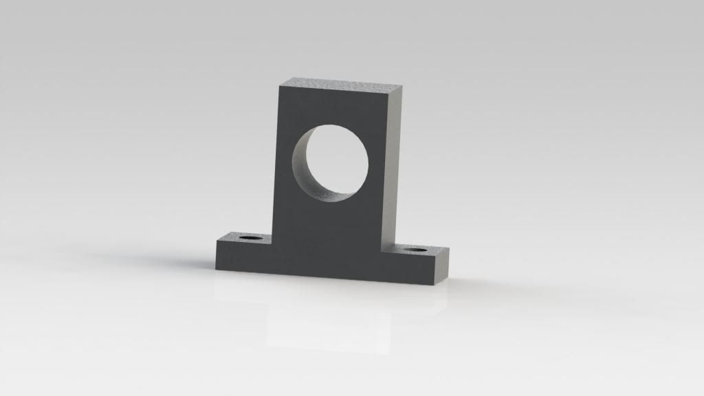
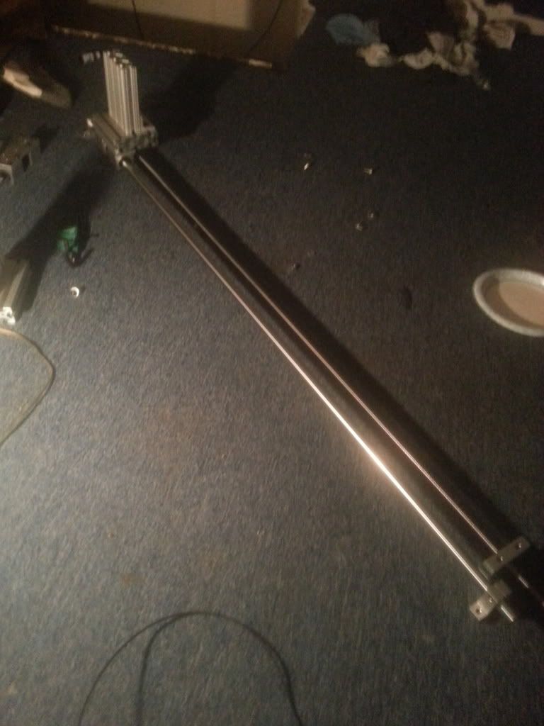
also here is a better representation of the y axis, not done yet but it uses cncrouterparts.com trucks and z axis
-
11-23-2012, 07:51 PM #27
Member
- Join Date
- May 2012
- Posts
- 231
If you are thinking that a bridge support system you could still have some flex in between the supports. The more solid you make the carriage support the less flex you will have.
-
11-23-2012, 09:27 PM #28
Registered
- Join Date
- Nov 2012
- Posts
- 59
Even with one every ten inches? Ive gotta believe that will make a drastic change in the flex. Originally Posted by dodger889
-
11-23-2012, 11:07 PM #29
Registered
- Join Date
- Jan 2008
- Posts
- 853
Playing with a model of your system in BeamBoy (free download ... try it!), a 10 inch span of 0.8" diameter steel rods will deflect ~0.001" with a 25 lb load in the middle. Deflection scales linearly with load, so you can add up your gantry components to see what static deflection to expect. Cutting forces will probably be 20 lbs or less in all directions. Acceleration forces will scale with the mass of the gantry+router, count on accelerations of about 10-20% of gravity, again in all directions.
If you can make your supports grab the rail to prevent side deflection, I would think 10" spans are OK. This is the tough part though, since the side walls of the pylons are thin, as you have found out.
Note that tightening your pylons to the base (wood?) will cause the wood to crush, changing the position each time and hence the position of the rail itself. Adding a 1/4" thick, 3" wide Al strip under the pylons, running parallel to the rails would prevent this crushing effect (less concerns about the underside, but big washers would help). As you can see, it is getting complicated, but doable.
After thought : instead of having long bolts (read : stretchy and bendy) passing through the pylon and base, consider short bolts that secure the rod to the pylon through hanger-bolts or the like. This puts the sideways forces directly on a short, stubby bolt, instead of long bolts and short thin sections of pylon wall. You can always shim the pylons to get the height right.Paul Rowntree
Vectric Gadgets, WarpDriver, StandingWave and Topo available at PaulRowntree.weebly.com
-
11-24-2012, 03:18 AM #30
Registered
- Join Date
- Nov 2012
- Posts
- 59
Originally Posted by PaulRowntree
im a little confused but i may not b reading it right lol, the pylons will grab the rod because its threaded every ten inchs, so i wanna take a fender washer on a bolt go thru the bottom of the 1" thick mdf, up thru the center of the pylon and screw into the threaded rod. then screw the pylons sides down with fender washers and nuts also. idk lol hopefully it will work better than nothing. i guess 100 bucks for ten of the pylons isnt to bad then just gotta do a dickload of machine work to them to get them to look like that. idk anyone have a cheaper better way of supporting the rail?
-
11-24-2012, 03:29 AM #31
Registered
- Join Date
- Jan 2008
- Posts
- 853
Ok, see if it works. Still, the long Al pylon base strip is probably a good idea to keep the pylons from digging down into the MDF when your reef down on the bolts.
Just for curiosity :
1) what is the threading on the bolts into the rails,
2) is there a flat area at the threaded hole, and if so, how big is it?
Cheers!Paul Rowntree
Vectric Gadgets, WarpDriver, StandingWave and Topo available at PaulRowntree.weebly.com
-
11-24-2012, 04:46 AM #32
Gold Member
- Join Date
- Apr 2009
- Posts
- 5516
LOL I wouldn't dishonor the name of Yoda; after all I am not a Jedi... yet. Still learning the ways of the Force.
There are some Thomson 3/4" linear rail supports on eBay. This is only .037" off the diameter of a 20mm rail. Since the rod sits in a v groove they should work fine; you may just have to drill some new holes to match the rod you have now.
Another thing you can do is mount extrusion to your table surface, then use the CNCRP blocks and rails on top of that. You could then use taller extrusion profiles on your table axis, and eliminate or shorten the gantry legs on both sides, which should aid in stiffness.
-
11-24-2012, 08:50 AM #33
Registered
- Join Date
- Nov 2012
- Posts
- 59
I believe 6 mm bolt thread. Originally Posted by PaulRowntree
No flat spot sadly.
I checked ebay. All I saw was 24" sections and they were over 100 a piece. Shwew Lol. If I didn't already have these rails id get something else. Hmmmm
-
11-24-2012, 08:50 PM #34
Gold Member
- Join Date
- Apr 2009
- Posts
- 5516
I don't know where you checked. I found 24" sections for $53. Also saw 20mm supports x 1000mm length for $75 or so. If you factored the cost of fabricating supports it's probably cheaper to go this route. You could cut the supports and spread them out as well
-
11-24-2012, 08:55 PM #35
Registered
- Join Date
- Nov 2012
- Posts
- 59
Can u post a link? That sounds like a winner Originally Posted by louieatienza
-
11-25-2012, 04:08 AM #36
Gold Member
- Join Date
- Apr 2009
- Posts
- 5516
Rail Support Unit SBR20-1000mm Shaft Supported for Linear CNC X Y Z | eBay
I've purchased stuff from leifromchina before and have been happy with the quality.
-
11-26-2012, 05:06 AM #37
Registered
- Join Date
- Nov 2012
- Posts
- 59
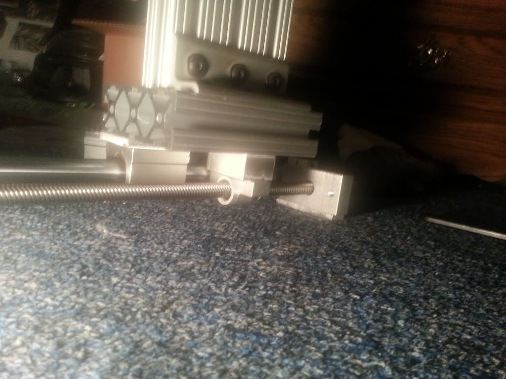
well i was looking thru some of the parts i had laying around( alot of the linear stuff ive had for several years stored away ) and realized i had four extra rod supports, which translated to 40 bucks, meaning i only need another 60 bucks to support every 10 " of the rail. so i think instead of going with the rail supports on ebay that are 24" long but would cost me around 200 bucks to support both rails im gonna at least entertain the idea of making my own supports.
DISCLAIMER : I AM NOT A MACHINIST AND REALLY DONT KNOW MUCH ABOUT IT, HOWEVER IM TOO DAMN CHEAP TO CONTRACT OUT MY WORK LOL, IT MAY NOT LOOK THE PRETTIEST BUT IT WILL WORK.
here is what i came up with, the best thing about this is u really dont need a mill for this u could do it with about any saw because all ur really doing is removing material and adding a hole.
ok i started by cutting the top off like so
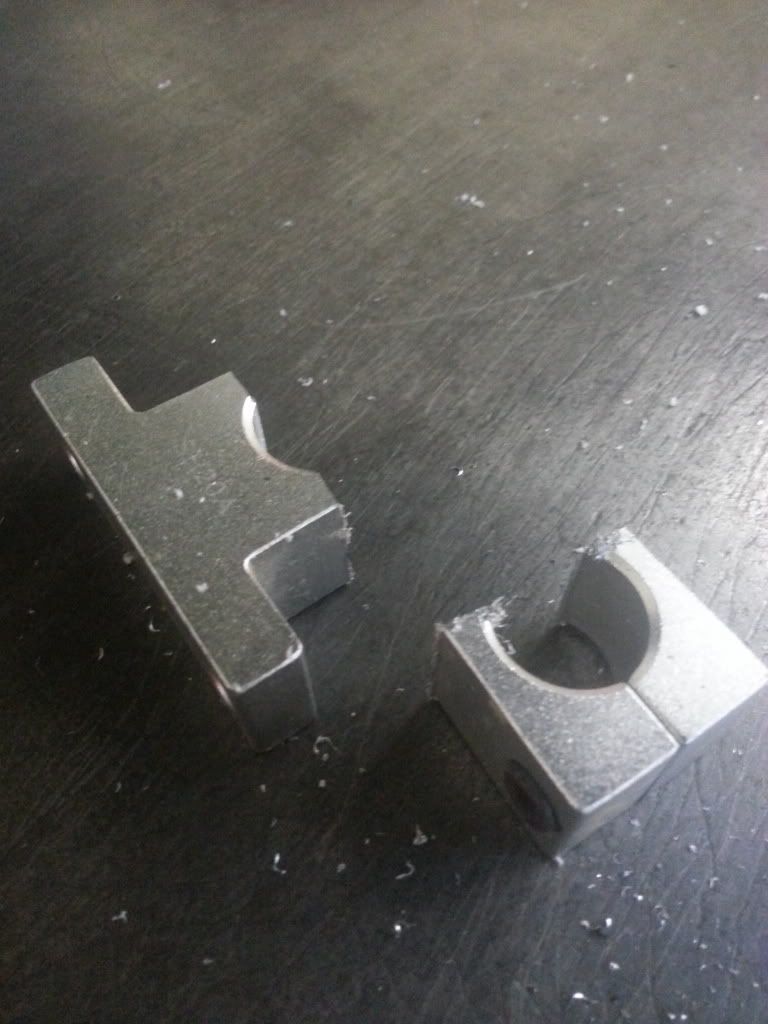
then i stuck it in a mill which u dont have to do it just looks a little prettier ( not that mine looks that great.
ended up with this
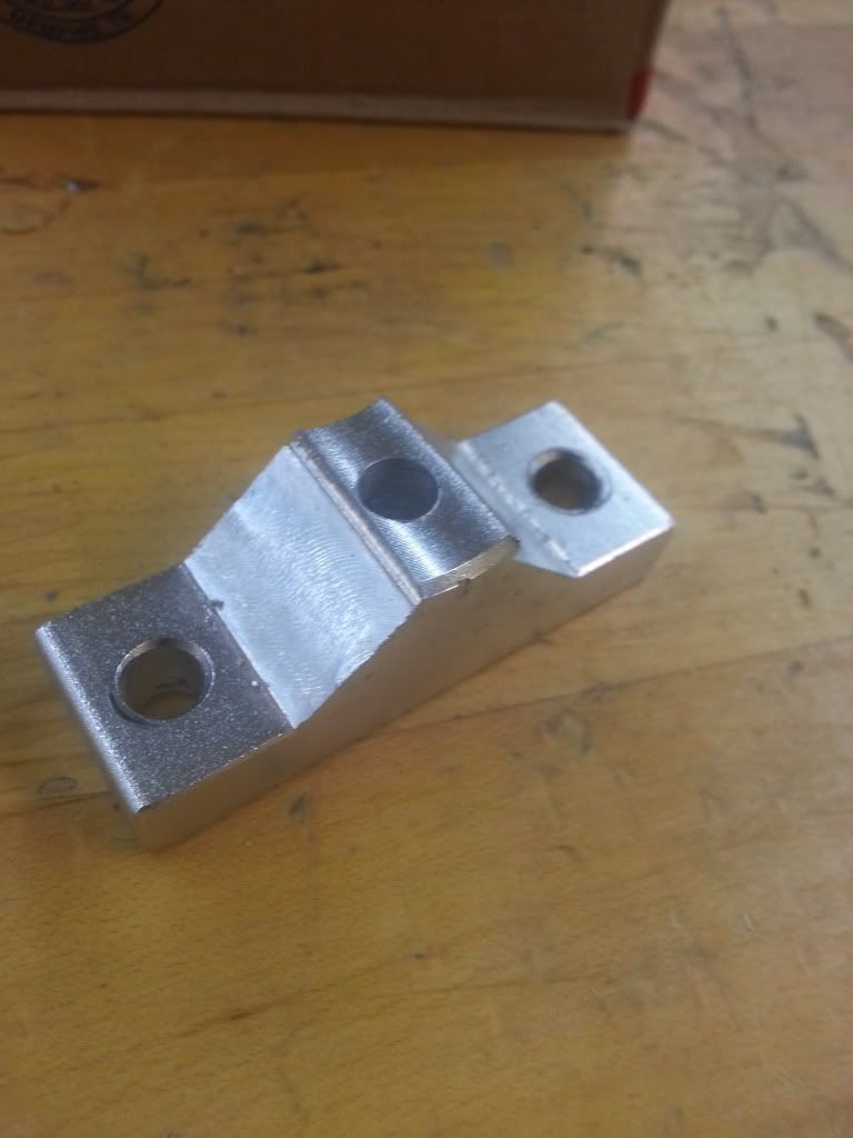
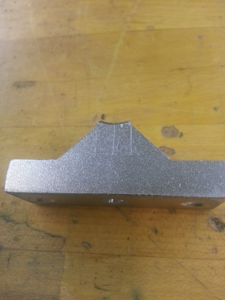
anyways i think this may do what i need it to do and on the cheap, also with four of them i think i can use 1 every 20 inchs to do some initial testing till i can buy and machine 6 more of them. idk ima download that beam program and see what kinda flex ill get
-
11-29-2012, 10:14 PM #38
Registered
- Join Date
- Nov 2012
- Posts
- 59
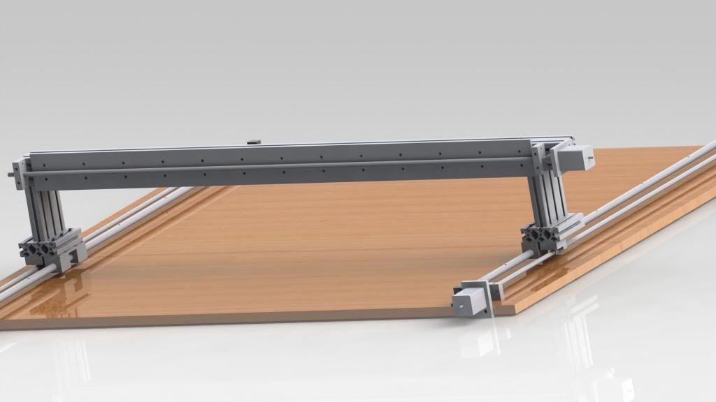
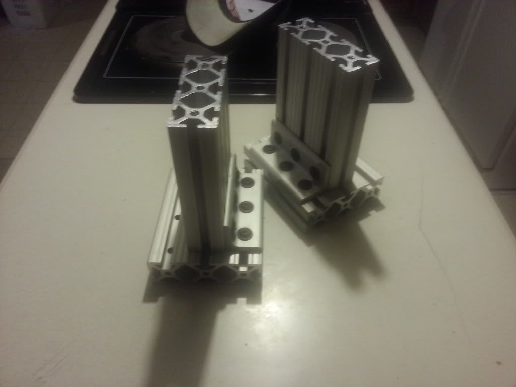
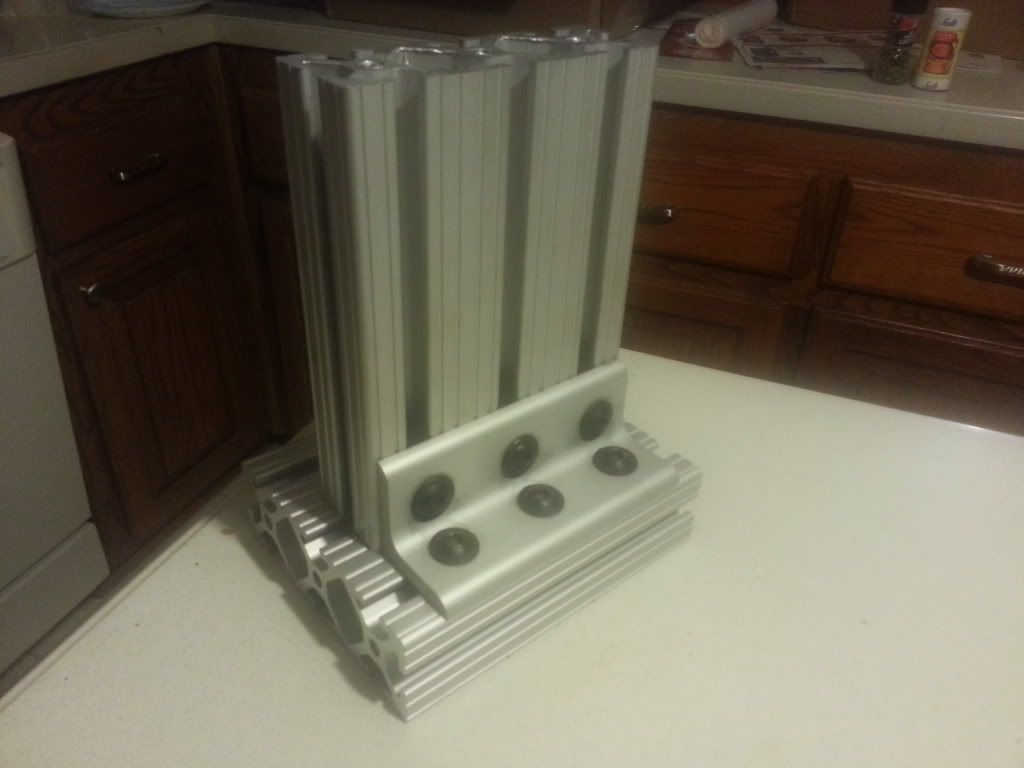
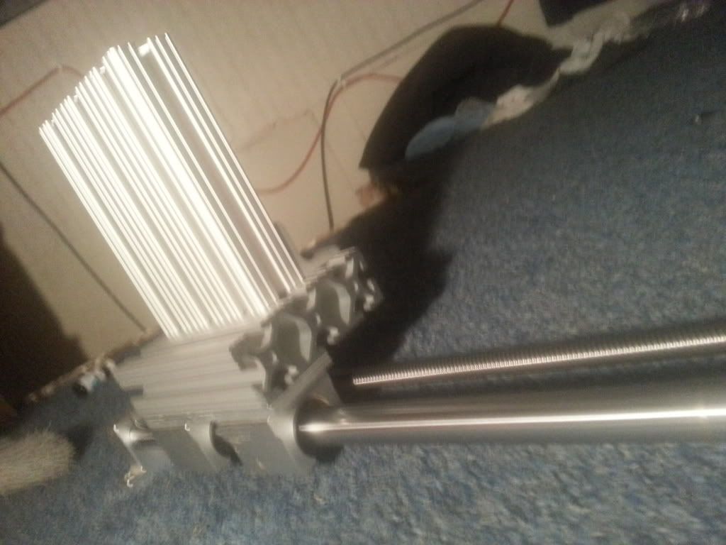
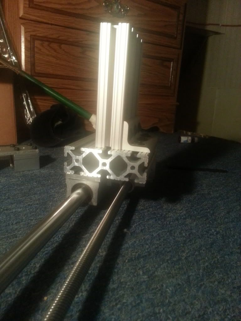
new parts
well i got some 80/20 stuff in the other day so i been working on it and heres what i came out with

-
12-01-2012, 04:53 AM #39
Registered
- Join Date
- Jul 2010
- Posts
- 567
Following along, :-)
This is an interesting thread as I can empathize with the OP on costs, and machinist knowledge(none).
-
12-03-2012, 04:28 AM #40
Registered
- Join Date
- Nov 2012
- Posts
- 59
yeah im trying to do a cnc that is cheap, easy to build and performs pretty good, maybe even do a little aluminum with it idk yet. not really looking for the fastest thing the planet, all and all i wanna i wanna try something different that hasnt been done yet and see if it works out

 Reply With Quote
Similar Threads
-
DIY BUILD. WHERE TO FIND PARTS IN CANADA
By Mikemann55 in forum Want To Buy...Need help!Replies: 4Last Post: 01-24-2017, 05:00 AM -
Easy Parts?
By 03ram2wd in forum Mini LatheReplies: 2Last Post: 12-17-2010, 01:50 AM -
Build Question - Partial machine, how do I complete?
By jross in forum DIY CNC Router Table MachinesReplies: 6Last Post: 11-04-2008, 01:48 AM -
...to find a machine or someone to build parts
By dabckid in forum Want To Buy...Need help!Replies: 2Last Post: 05-31-2008, 09:25 AM -
Easy way to find the radius?
By turboboy in forum MetalWork DiscussionReplies: 7Last Post: 09-27-2006, 03:20 AM
