


This is going to be a machine with a 2'X4' cutting area. It is going to be made out of steel with a mdf cutting bed. Im trying to make it out of one 20' square 1"x1" OD .090" wall or .125" wall, one 20' 2"x.125" strap, and 1' 3"x.125" round tubing. To build this machine you will need access to a welder, drill press/cordless drill, and someway to cut the steel accurately. The cutter could be anything from a metal bandsaw, oxy-acetylene torch,plasma cutter, hacksaw, etc. i am trying to make the cuts and welding as simple as possible while keeping a accurate and durable machine.
I am going to post files when i am done building with all the measurements and details. I am currently building the machine in my spare time. I will try to have it done in a timely manner
Hazardous
Thread: 2' x 4' Steel Machine for Router
Results 1 to 15 of 15
-
10-13-2011, 08:40 PM #1
 Registered
- Join Date
- Apr 2011
- Posts
- 51
2' x 4' Steel Machine for Router
-
10-13-2011, 08:45 PM #2
Registered
- Join Date
- Apr 2011
- Posts
- 51
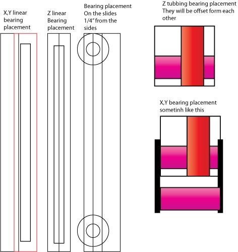
These drawings are crude and may change before the final product. They may not be to scale yet to save picture space.For the z axis it is going to be a square cage with the router in it and a square cage around that will have the slides for y axis and linear rails for z axis. The linear rails are to scale but the table size one is not i need to finish my router mount witch is going to determine the length and width of the y and z axis. I quite havent decided what to do with the x axis the 4' span. It could be either design with flat welded or just square. I have not decided on what to support the x rails with yet either at first it will probably be mdf or 3/8 .09 square at a set distance.
Z axis 12"
X axis 48"
y axis 24"
That is the table cutting size so they lengths will be bigger than those dimensions but i can mimic your lengths by supporting the rails and testing them.
Hazard
-
10-13-2011, 08:57 PM #3
Registered
- Join Date
- Apr 2011
- Posts
- 51
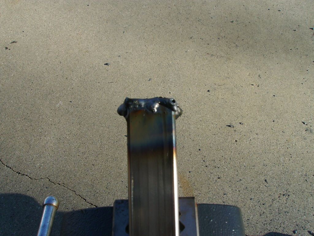
The 3" x.125" round is going to for the router mount. I have started today an the picture will describe it better than explaining it. i cut it with a bandsaw and i used a plasma cutter to cut the rest.
 make sure your band saw blad is tight look at the second pic. its all crooked its my own fault for trying to make it go faster though.
Make sure you use guides with the plasma or oxy-acetylene torch to make straight cuts. pic3
Picture one is close to the final product. it still needs more cut out or grinded out and tabs or something to make it close around the router.
By the way i spent 25$ for all the steel so far. The two 20' and 1' fo 3" pipe.
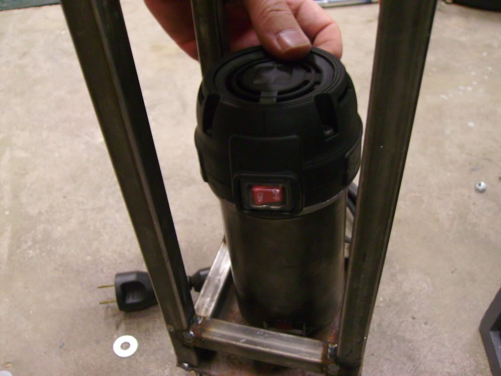
This is a clamp for my router a porter cable 450. 120$ from amazon for a 1.25hp router not bad. Its a lot better than a laminate cutter... pic4
Hazard
-
10-15-2011, 03:04 AM #4
Registered
- Join Date
- Apr 2011
- Posts
- 51
Any tips to a guy building his first machine would be appreciated.
Hazard
-
10-15-2011, 08:42 AM #5
Registered
- Join Date
- Apr 2011
- Posts
- 51
So to figure out what pipe to buy to clamp your router take a zip tie and tighten it then cut it off and measure. that is the id of the pipe mine was 2.73 something ill post when i remember exactly so 3 inch od - the 1/8th wall is 2.875 so i would have to cut out .102" of an inch but a little more is better.
I finished my clamp.
Notice how close the seam is I should have grinded more out of it ohh well it clamps good enough for me. the square on the outside is 5/8ths square .09 wall or something like that I already had some laying around but it fits 1/2" head bolts very nicely cut it at at a steep angle and weld on. Sorry for the bad welds half it was mine it was my second time welding ever. I also used some more spare round sorry idk the size the piece is like 8 years old and I dont care to measure if I dont have to. used vice to make fit the square. Picture one shows the bolts and spacers. picture 3 is an example of not planning ahead i have less than 1/2" in the clamp...
I have decided that i am going to post my measurements at the end as well as a guide to adjusting to fit a different router. i am going to try to make it as small as posible for my router i will also post feedback on durability router
I also found out why my bandsaw was not cutting straight the blade was on backward
Hazardous
-
10-15-2011, 11:18 AM #6
Community Moderator
- Join Date
- Mar 2003
- Posts
- 35538
It looks to me like those bearings are using ~2" spacers? I think you'll see a bit of flex with the long spacers and the 1/8" bar they're mounted to. But I haven't seen enough to really know what you're doing yet. Originally Posted by hazardouschurch

Good luck.Gerry
UCCNC 2017 Screenset
http://www.thecncwoodworker.com/2017.html
Mach3 2010 Screenset
http://www.thecncwoodworker.com/2010.html
JointCAM - CNC Dovetails & Box Joints
http://www.g-forcecnc.com/jointcam.html
(Note: The opinions expressed in this post are my own and are not necessarily those of CNCzone and its management)
-
10-15-2011, 05:35 PM #7
Registered
- Join Date
- Apr 2011
- Posts
- 51
Hey thanks for the input i hadn't really thought of that but I think it should be fine as long as my holes are the right size and i use a body washer on the other side of the flat. I havent yet decided if i want to weld them on or if I want them bolt on. If I weld it I would have to make room for the bolts and I would probably weld gussets in between them. I had to do the router clamp to fint the smallest sized carriage possible for me and to have the lengths of the linear be the smallest possible. Also the 2" strap is a quarter inch off the minimum amount needed we will all so be welding it on the outside and the inside of the square. So there should be little flex i think. we will also be pushing the bearings as close as possible to the square and the main load bearing one is on top of the square that could be a pint of weakness. on the bearing carriers i could also weld some small round to make the surface area increase or weld the bolts in and make them studs to make them stiffer. I could also use round to support the long stretch of the bolt and gusset that.
I still havent decided quite what to do when i get there for the bearings but I will know when I get there.
I have been working on race cars and cars since i was born im 19 years old. So i have been doing the real work for about 10 years my dad who taught me has been racing for 30 years and is a very proficient welder and fabricator you will probably notice his welds on the clamp and then my ugly ones the close ones in the picture. He knows more about steel than me and he is the one that came up with the idea. If it ends up we need more steel and the carriers i will go get some 1/4" plate and do it out of that. I can change things but its just more money and my own fault if i do for misengineering. Thanks for the input I will defiantly put that in mind.
I will try to get the inner cage done today but the rest should go quickly because it it bigger pieces and easier to fabricate. If you think of anything else bring it up i wont get my feelings hurt I would rather solve the problem when im still fabricating it than after i paint it.
Hazardous
-
10-15-2011, 07:32 PM #8
Registered
- Join Date
- May 2010
- Posts
- 88
A motor that beefy should cut metal with the proper blade. Have you ever tried something like that? I'm still noodling on the spindle. Originally Posted by hazardouschurch
The cost of steel is amazingly cheap compared to Aluminum. I was talking to a metal dealer a couple of weeks ago and he informed me that there is a lot of price fixing going on with Aluminum. Seems goldman-sachs is trading the commodity at one end and is involved in warehousing and releasing the raw product on the other end. Their warehouses store 20+% of the world supply or some insane thing like that.
Seems that they release the minimal amount of material per day necessary by law to buyer. So there is a ton of aluminum sitting in warehouses but people like Coca Cola are waiting months to get their aluminum. Really strange legal crap inside the commodity industry I don't claim to fully understand. I googled and sure enough Coca Cola is up in arms about it as are a lot of people.
Here's a link:
http://www.reuters.com/article/2011/...76R3YZ20110729
-
10-15-2011, 09:17 PM #9
Registered
- Join Date
- Apr 2011
- Posts
- 51
what do you mean?
The bandsaw or router?A motor that beefy should cut metal with the proper blade. Have you ever tried something like that?
The bandsaw is a metal bandsaw. The blade popped off a few months ago and I forgot to check the direction of it and it was filing the hell out of the piece not cutting it. I put a new bimetal balde on and it fixed the crooked cut like butter idk if you noticed but the bottom is a lot straighter now.
I dont know if i wanna cut aluminum with the router if i need to cut it ill hook up my plasma cutter to the machine
The router mount id probably something like 7$ in steel including bolts. i had to get a special piece cut of the 3"
Hazardous
-
10-30-2011, 12:04 AM #10
Registered
- Join Date
- Apr 2011
- Posts
- 51
So this is what we have come up with so far. the drawings kind of crude but this will be the z axis the carriage and the lineair rails. we decided to use more types of steel because I would like this machine to be very functional and not be inaccurate and suck basically. we have decided to get pieces of round that will fit the bolts that we are using for our bearings 3/8 bolts i have to see what we can get for steel that small and i will post the size. this will be the hardest thing to find because it is not common. the design change also includes more technical welding so this is turning from easy to moderate machine to build. we also are going to make the inner cage out of 5/8" square i think the piece we have is .090 wall or .060 wall both will be ok for our needs. I didn't buy this piece i had it in our steel pile thats why i dont know what it is i will post all the exact sizes when im done with it. these changes should make it a lot stronger and stiffer.
Any questions or suggestions let me know.
Hazard
-
02-21-2012, 06:49 AM #11
Registered
- Join Date
- Apr 2011
- Posts
- 51
Sorry for the delay I got really busy with school and it ended up taking all of my time. Im going to at least try to get one thing done a week and post when I feel appropriate.

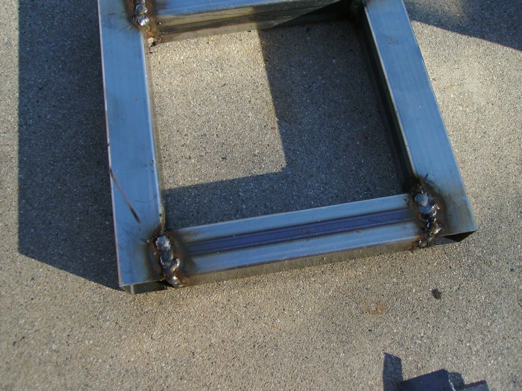
So this is how I am squaring up the z axis carriage. Plates with all thread to help square it up I used metal so that I could tack them and make the machine more accurate. You could use wood just keep in mind that the metal expands and has the potential to warp that is why I tacked the outside so that I could minimize the warping. The vertical pieces were 12" long. To get the side pieces I cut them close to where I wanted them then sanded with a belt sander and numbered them to get a custom fit.
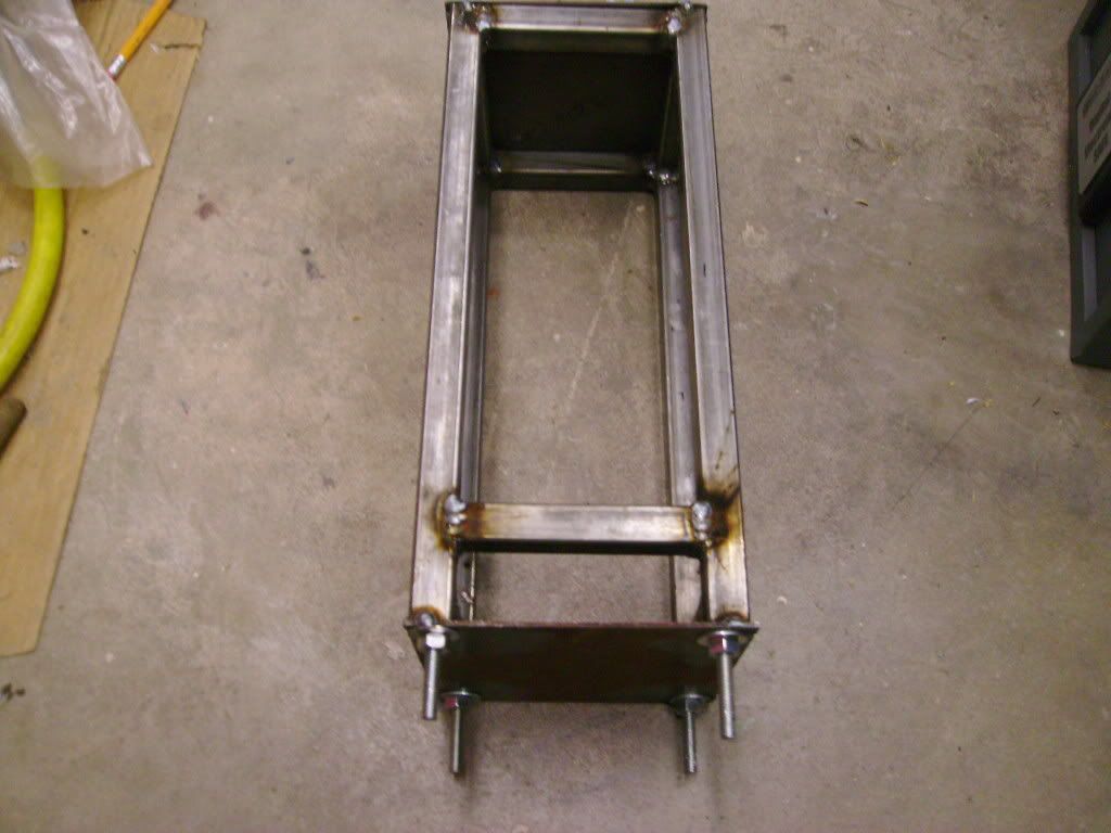
The sides were just shy of 3.65". Some of the vertical pieces were warped so overall accuracy of this pieces was arround +- 5 thousandths. The one that is spaced up is for the bit release.
-
07-21-2012, 06:29 AM #12
Registered
- Join Date
- Apr 2011
- Posts
- 51
so i am finally on break from school at the moment i switched majors to physics and its a lot more harder classes but i love it. So during the corse of the winter and spring quarters i have been very busy and have not had time to work on the cnc machine. Now since i have time I got some more parts to continue building my cnc machine. first off i have decided to change the way my bearings are attached in favor of something much stronger. im going to start this tomorrow hopefully and get her going again
Also decided to use proper 8mm bolts for the bearings
sorry for revving dead thread
-
10-20-2012, 09:08 PM #13
Registered
- Join Date
- Apr 2011
- Posts
- 51
Got my 8mm X 50mm bolts lock nuts and washer's all grade 8.8. I also got the odd sized drill bit to drill the holes for the supports going through the tubing 35/64 really odd size but it allows me to use 3/8 schedule 40 pipe to have the bolts go through for more adjustment and allowing me to make it less precise just need to make it square.
Pictures of the z/y bearing carrier tonight probably have 20 holes left 20 of the inserts to weld and 4 brakets to make and weld as well as welding it together. Well see what i can get done today.
-
12-21-2012, 06:51 AM #14
Registered
- Join Date
- Apr 2011
- Posts
- 51
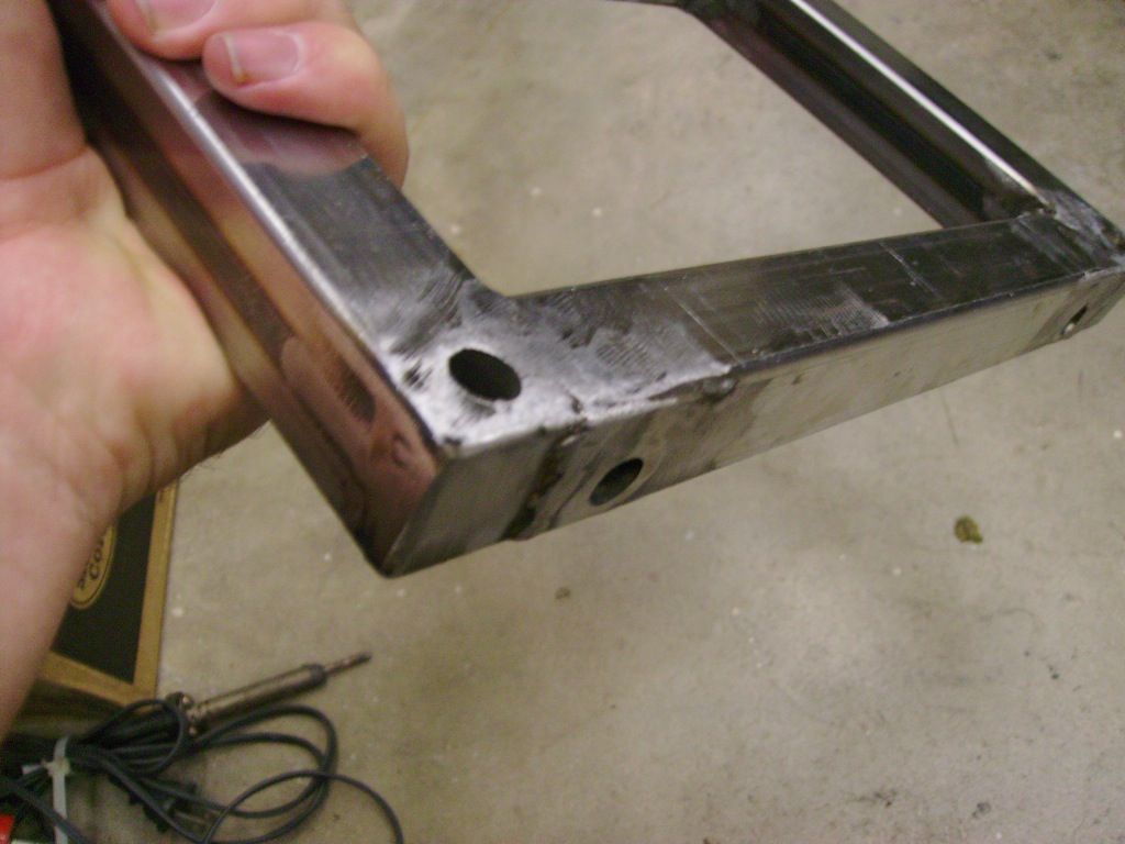
Deadline time bones done by christmas?

Welds without gas
With gas
-
12-22-2012, 08:45 PM #15
Registered
- Join Date
- Apr 2011
- Posts
- 51
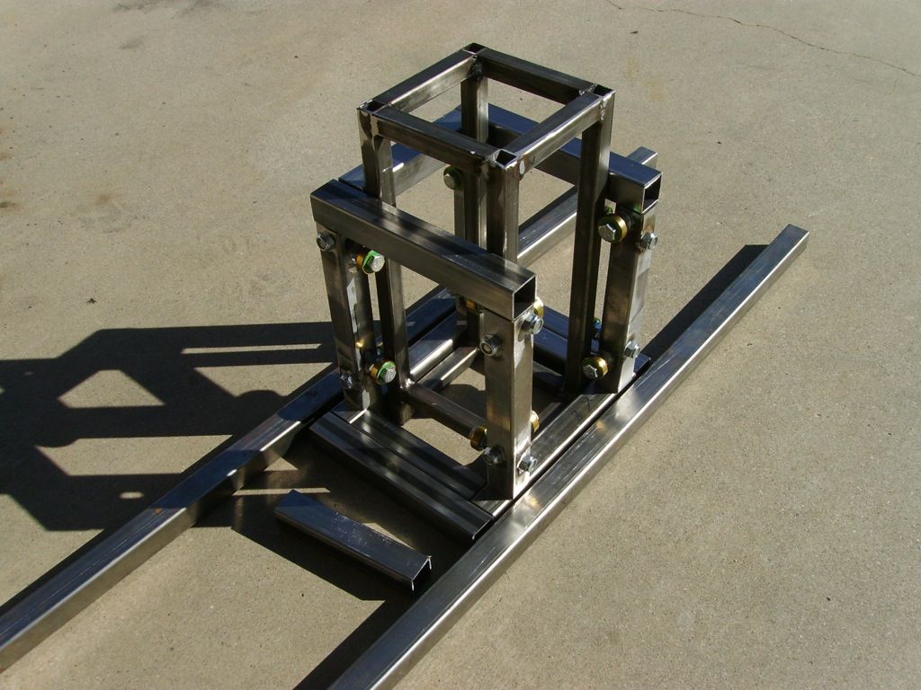
So i was planning to have the z/x axis carrier done yesterday but i didn't seem to realize that i made a piece on old measurements that was 1/2 too small so trying to clamp it for welding made me want to break some stuff because i was fiddling with it for 3 hours before i realized my mistake. However once this piece is done is easy after that.
I got the carrier for the x axis done minus the z axis parts. In the picture it looks like its off but its not just the angle of it.

 Reply With Quote
Similar Threads
-
Porter Cable router question.
By Drools in forum DIY CNC Router Table MachinesReplies: 6Last Post: 08-12-2010, 07:46 PM -
Toolholder for Porter Cable router
By SpookyDad in forum Metalworking- / Woodworking Tooling / Manual MachiningReplies: 4Last Post: 03-26-2010, 03:29 AM -
Porter Cable router and drilling
By THend in forum CNC Machining CentersReplies: 2Last Post: 03-11-2009, 02:16 AM -
porter cable 7518 router hot
By woodman08 in forum WoodWorking TopicsReplies: 13Last Post: 10-21-2008, 10:17 PM -
Porter Cable 890 Router and collet
By H2ODiver in forum CNC ToolingReplies: 4Last Post: 01-21-2007, 03:33 AM
