


Hi all,
Looking for some input...
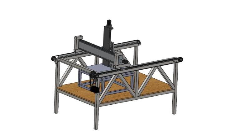
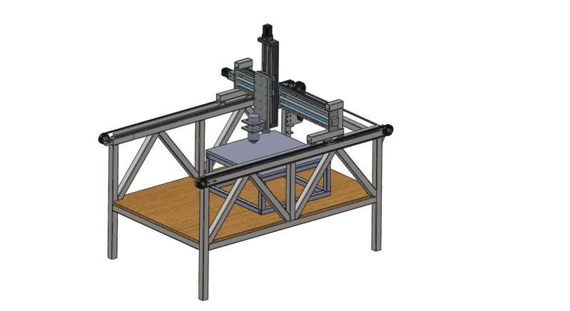
Here's my new build to cut MDF 'like' foam to make tools and masters for composites. (starting a carbon fiber home furnishings company)
The max part size is 5' x 3' x 1.5'.
The Z is adjustable on the 1" thick drop down plate and figure I'll make a platform similar to what's in the photos for majority of my parts. But it will be nice to have the flexabilty for the larger parts when that time comes. Purchased the Y and Z off ebay already for $400 each. One is a Parker and one is a thomson. The thomson needed a $40 bearing to make it like new again. The Parker was brand new. Both of these retail for $2300 new. For the Y, it will have steel reinforced 2x 3/4" belts driven by a Nema 34 3.3:1 gear reduction motor. The slides and blocks are off fleabay (on their way). The idler end caps slide in and out to adjust the tension. The sliding gantry weight is estimated to be 100lbs!
The spindle will be the 2.2kw Chinese water cooled fleabay specail. Figure since I plan to do this in my garage for a while, I should keep the noise down.
The main structure will be 2" x 2" tubing, approx 1/8" wall.
I'm estimating a $3k build without comp and software. Thoughts? I still need to add some leveling feet but would like your inputs! Thanks
Keith Ray
Results 1 to 20 of 27
-
12-04-2012, 03:27 AM #1
 Registered
- Join Date
- Dec 2012
- Posts
- 52
Keith's Steel Build, 5' x 3' x 1.5'
-
12-04-2012, 10:36 PM #2
Registered
- Join Date
- Feb 2004
- Posts
- 304
Well first of all congrats and good luck with the new business. The thing that sticks out to me is that you have good triangulation in the x direction, but not in the y. You can add braces at the back on top like the x has, and if you really want the front open you could make the braces bolt on. If you don't want to do that, I would at least make the legs bigger and do the triangulation below the table.
-
12-05-2012, 12:21 AM #3
Community Moderator
- Join Date
- Mar 2003
- Posts
- 35538
10ft long 3/4" belts are going to have a lot of springiness, especially with rapid direction changes.
Gerry
UCCNC 2017 Screenset
http://www.thecncwoodworker.com/2017.html
Mach3 2010 Screenset
http://www.thecncwoodworker.com/2010.html
JointCAM - CNC Dovetails & Box Joints
http://www.g-forcecnc.com/jointcam.html
(Note: The opinions expressed in this post are my own and are not necessarily those of CNCzone and its management)
-
12-05-2012, 01:20 AM #4
Registered
- Join Date
- Feb 2004
- Posts
- 304
Yes, you will need some glides to keep them from bouncing up & down during speed/direction changes. Originally Posted by ger21

-
12-05-2012, 01:28 AM #5
Community Moderator
- Join Date
- Mar 2003
- Posts
- 35538
I'd be more concerned about flex along their length than bouncing.
Gerry
UCCNC 2017 Screenset
http://www.thecncwoodworker.com/2017.html
Mach3 2010 Screenset
http://www.thecncwoodworker.com/2010.html
JointCAM - CNC Dovetails & Box Joints
http://www.g-forcecnc.com/jointcam.html
(Note: The opinions expressed in this post are my own and are not necessarily those of CNCzone and its management)
-
12-05-2012, 01:45 AM #6
Registered
- Join Date
- Feb 2004
- Posts
- 304
By flex I assume you mean stretching? I guess I'd be concerned about both, accel/decel will be limited. Originally Posted by ger21
-
12-05-2012, 02:00 AM #7
Community Moderator
- Join Date
- Mar 2003
- Posts
- 35538
Yes, stretching. But more like a spring, as the stretching isn't permanent.
Gerry
UCCNC 2017 Screenset
http://www.thecncwoodworker.com/2017.html
Mach3 2010 Screenset
http://www.thecncwoodworker.com/2010.html
JointCAM - CNC Dovetails & Box Joints
http://www.g-forcecnc.com/jointcam.html
(Note: The opinions expressed in this post are my own and are not necessarily those of CNCzone and its management)
-
12-05-2012, 02:44 AM #8
Registered
- Join Date
- Feb 2004
- Posts
- 304
Yep, so Keith if you want input on the design you should let everyone know what kind of performance you expect. It's probably rigid enough to cut high density foam at a reasonable feedrate, but dual motors arranged like the servobelt drives would get you much better performance.
-
12-05-2012, 06:00 AM #9
Registered
- Join Date
- Dec 2012
- Posts
- 52
Kevin and Gerry, thanks for the good info! Looks like I need to source some new belt components or start looking how to do a r&p on a budget. Thanks again.
-
12-10-2012, 04:23 PM #10
Member
- Join Date
- May 2012
- Posts
- 231
X brace under the table height would help a lot for the Y axis. Leveling legs can be made from harden 3/4 all thread with coupling nuts welded to the bottom of the legs. Here is something you might want to look at instead of a extra platform why not make an adjustable table
-
01-18-2013, 03:32 PM #11
Registered
- Join Date
- Dec 2012
- Posts
- 52
Stepper test...it's alive
Hey guys,
Figure I'de get the electronics working before I started to buy the rest of my steel and misc hardware (only about $800 or so left).
Anyways, I knew I would have some bugs just because it's well...electroncis and I'm no EE!
After some debugging...I'm happy to report I've gotten one of the steppers working! See below, nothing special but a good start!
https://www.youtube.com/watch?v=ZMu1dCAh7zg
-
01-21-2013, 07:25 PM #12
Registered
- Join Date
- Dec 2012
- Posts
- 52
Got the z axis hooked up and the control box cleaned up. As of now, all the drivers are functional along with the estop. Waiting for a new cable to test out my original breakout since it has a relay control for the router. Weekend of feb 2nd should be getting all the steel to make it look like something!
 )
)
[ame=http://www.youtube.com/watch?v=ZNu7YD-7ROE]Cnc stepper test #2 - YouTube[/ame]
-
01-22-2013, 09:02 AM #13
Registered
- Join Date
- Apr 2005
- Posts
- 253
looking good
 I'll get it finished sometime after I start it.....
-
02-19-2013, 07:46 PM #14
Registered
- Join Date
- Dec 2012
- Posts
- 52
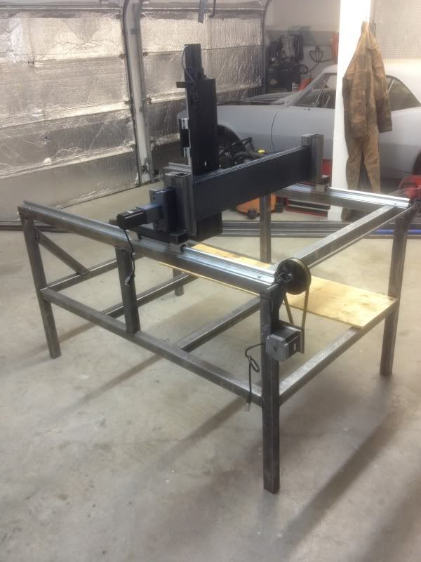
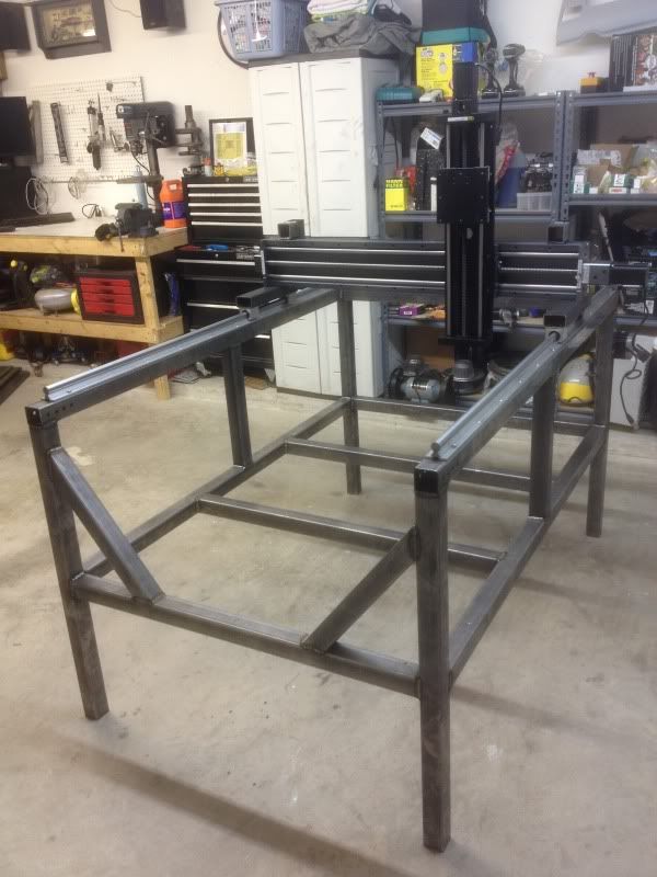
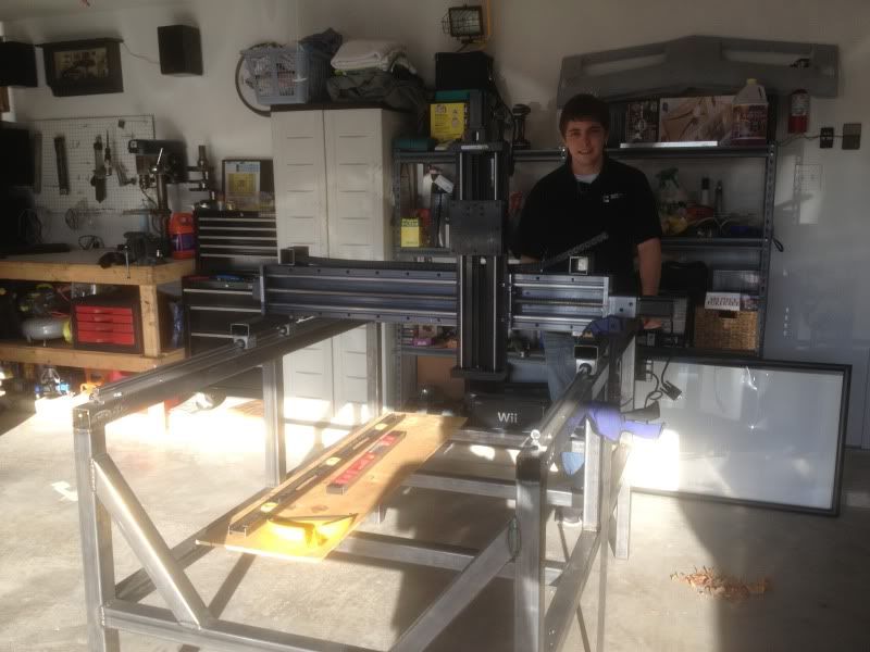
got a little work done
Got a chance to get the basic frame welded up and mounted up some of the axis to see how she rolls with full weight. Need to get the front idlers/tensioners mounted up along with the belt mounting tab on the sides then can do the first tests! Maybe even get the 1" thick drop plate drilled so I can do some cutting tests?
-
02-19-2013, 09:48 PM #15
Registered
- Join Date
- Aug 2012
- Posts
- 6
LINEAR GUIDES
Hi Keith, nice job, i'm in the process of researching a cnc router build 4" x 3" to m/c guitar bodies and necks. i'm curious about the size of your linear guides on the x axis, are they 16mm or 20mm supported shafts.
thanks in advance
Dermot
-
02-19-2013, 10:00 PM #16
Registered
- Join Date
- Dec 2012
- Posts
- 52
Thanks!
They're the 20mm
Paid $230 US for the 1625mm long rails with blocks
-
02-19-2013, 10:46 PM #17
Member
- Join Date
- Apr 2007
- Posts
- 1955
You have a great looking machine there, with very nice components. Please reconsider the belt drive, and I will tell you why.
I spent 2 years researching belts, pulleys, shafts, etc. trying to prove that belts were a good path for cnc routers. Once I found the error in my thought process, it made perfect sense.
If you look at the force ratings for toothed belts, they are nearly all rated based on three assumptions:
a) The motion is in one direction most of the time
b) The strength number is based on tooth strength, not on belt stretch
c) For positioning situations, it is assumed that it needs to "eventually" get to the final position (but could go past for a fraction of a second) not "go directly to position X and exactly stop there".
For a cnc router, what is needed, is a belt strength rating based on achieving the actual goal of:
a) Going almost exactly to position X, and stopping there
b) Strong enough to hold things still during cutting without flexing / stretching.
I did the actual calculations needed for this using one of the stronger belts on the market, Brecoflex AT10. For this belt, basically the length : width ratio needs to be in the range of 10:1 - maybe 15:1 for cnc wood cutting.
-
02-19-2013, 10:56 PM #18
Member
- Join Date
- Apr 2007
- Posts
- 1955
In your case, the belt length is approx 10 ft on each side. That means the belt width should be in the range of 1 ft wide. Since your system has two belts on that axis, it is viable to split this between sides, so the belt width needed is 6 inches on each side. This is not quite the same, but it is close enough. Brecoflex does make a belt like this and matching pulleys, but that is as wide as I have seen them.
The other thing to watch for is flex in the jack shaft (cross shaft). The tension of the belts will pull pretty hard on the shaft ends, causing it to bend and throw off the belts. You can avoid this by adding another bearing and support bracket on the outside of the timing pulley to hold the shaft still.
Adding another bearing at the center of the jack shaft will also help with flex.
You have a really nice machine there and I almost didn't want to say anything, but using too narrow of a belt for these systems is a real party killer.
-
02-19-2013, 11:05 PM #19
Registered
- Join Date
- Dec 2012
- Posts
- 52
Harryn,
I trully value your response.
My process for proving that it's okay was working for a composites shop for a year that had a home built cnc machine with only a single belt to drive the gantry. It was much longer in length (nearly double) and again, only had a single belt. Fingers cross I don't get bit, but I'm going forward with the design.
I plan to just cut MDF like tooling foam with a rough pass, leaving 1/8" then go back with a final pass to get the needed accuracy. Majority of my passes will be along the y axis going back and forth to limit the holding force needed by the x axis.
I know the machine will have it's limits but hopefully proper tooling paths will overcome them enough to get good quality parts.
It worked for a company that did $10 million a year in one off composite parts for all major aerospace defense companies, it hopefully will work for an amateur like me.
I will add an extra bearing support on the jackshaft however. I get 1/16 of flex at the pulley/gear when I tight up the belt that wraps around the stepper. Figure it will only increase running it.
-
02-20-2013, 07:42 PM #20
Member
- Join Date
- Apr 2007
- Posts
- 1955
Thanks for that input. You are right, the calculations included some conservative assumptions about cutting loads and accelerations, which you probably will not have.
What kind of foam are you planning to cut ?

 Reply With Quote
Similar Threads
-
Keith's DIY CNC build
By cyberkeith in forum CNC Wood Router Project LogReplies: 21Last Post: 03-30-2016, 02:41 PM -
Mint's Build Aluminum/Steel Build thread.
By FreshMint in forum Maintenance DIY DiscussionReplies: 0Last Post: 10-31-2011, 04:18 AM -
2nd Build - Steel and Al 3'x5'
By Woodbutcher-59 in forum CNC Wood Router Project LogReplies: 47Last Post: 10-28-2011, 10:20 AM -
keith
By Keith rumsey in forum Plasma, EDM / Other similar machine Project LogReplies: 0Last Post: 07-13-2011, 06:59 PM
