


Mike,
As someone else said there isn't anything on the BOB that could create that much damage. I would look at the stepper driver especially the wiring. Ethernet cables are used to interconnect the BOB and driver but ethernet cables come in two flavors, one swaps some pins around instead of going straight through.
I noticed in one of the photos the middle stepper drivers is installed upside down as compared to the other two... double check your wiring, it will be reversed right to left from the other two.
I don't have that driver here but I looked at the data sheet. There should be nothing present on the port that interfaces to the BOB that generates any voltage. It is actually optically isolated. Maybe take a peek inside it to make sure a screw or nut didn't fall inside and short something.
Switching to another stepper will not likely correct the problem since in a working driver it is completely isolated from the BOB. In addition swapping to a different motor with different torque curves and inductance will change the maximum speed the motor can move at and how quickly it can accelerate. Ideally you want all three axises to respond the same but often the Z axis is slower than the other two. Changing the motor could get you to a point the machine will need to run slower to compensate for the mismatched motor. This will become apparent when milling circles or other profiles.
My gut says the driver is the cause but I'd double check the cabling first. Disconnecting the cable to the BOB you could power up and check voltages at the driver terminals normally connected to the BOB. None should have AC voltage and probably all should have 5 volts DC or less on them.
Charlie.
Charlie.
Thread: NM-145 purchased
Results 21 to 36 of 36
-
02-15-2013, 03:04 AM #21
 Registered
- Join Date
- Jan 2011
- Posts
- 63
Visit http://www.shadowspawnllc.com to see what enhancements I have available for the NM-145.
-
02-19-2013, 06:04 AM #22
Registered
- Join Date
- Jul 2010
- Posts
- 41
spindle motor wiring
I pulled the y axis plugs off and put them on another stepper drive and everything seems to move as normal. but I am still unsure of wether it is completely the stepper drive that is causing the issue or not. I went ahead and have a new stepper drive coming. It should hopefully be here before the big snow storm hits on Wednesday. John at novakon mentioned that the trace that burnt up could be due to a short in the contact relay for the coolant pump. I'm wondering wether or not I can run the coolant pump through the new VFD output relay and be able to toggle it on and off when the spindle starts up. It's a GS2 series form Automation direct.
I opened up the stepper drive that is possibly at fault for the Y axis and did not see any damage whatsoever on the inside.
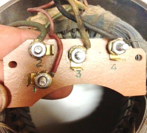
I have been trying to email charlie and John about the spindle motor wiring hookups as I am not using the BOB that charlie is using on his spindle motor upgrade kit. I am using a OEM Novakon replace BOB Rev2 board.
This is what I came up with between Charlies writeup and novakon drawings for the rev2 board.
Spindle start/stop= spindle enable on rev2 board
Analog spindle speed= spindle control connector on rev2 board (green ground and red +5V) or external wiring terminals have a grnd and +5V terminals on that also.
So I clipped off the old white flat plug that went to the old novakon VFD. I then stripped the green and red wires and put them on terminals ACM and AI on the new VFD. When I power up the system and go to mach3 the spindle automatically starts up and runs at about 3104 RPM which reads on the readout on the VFD itself. I have absolutely no control through mach3 to speed up slowdown or shutoff the spindle motor. Where am I going wrong on this. Am I using the wrong leads for the +5v or is it a ports and pins setting. I am lost right now but at least it is powering up. Can anybody point me in the right direction as this is something totally different than what has been done before on an nm-145 mill. I'm tired and am going to head to bed. Try something different tomorrow and see what happens. Thanks for all the help everyone I appreciate it.
Mike H.
-
02-20-2013, 06:30 AM #23
Registered
- Join Date
- Jul 2010
- Posts
- 41
update
Well I have control to the spindle now. I can start and stop it through mach3.
Only problem now though is no matter what rpm I give it to try and run at I can't get it to go over a few hundred rpm. I let it run for to long and the vfd pops up an overload error code on the vfd display and locks the spindle out. I have to pull the spindle enable plug and plug it back in to get it to respond again. I think I'm gaining on it. Not sure why I'm not getting the 0-10v to work correctly.
-
02-27-2013, 04:32 AM #24
Registered
- Join Date
- Jul 2010
- Posts
- 41
waiting for parts
As I am waiting for parts I decided to fix the trace that burned up on the new bob. Come to find out that the trace that fried is for the Y axis. So I soldered on a new wire to fix the trace on the board. Re-coated the other trace beside it with some clear fingernail polish. Decided to hookup the original stepper drive to see if it still worked and low and behold it still did. I left the Y axis proximity sensor plug off the board since I now know I need to get all new for that. I still have a problem with the Y axis though. It still will only go like a half an inch at a time and not full movement front to back. Should I be looking for something maybe binding on the ways or gibs or maybe a bearing or even motor.
Now I have 4 new stepper drives with a breakout board and parallel cable and also a 36vdc power supply that is going to sit and collect dust I guess.
-
03-04-2013, 04:08 AM #25
Registered
- Join Date
- Jul 2010
- Posts
- 41
it's alive again
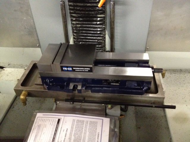
So after moaning and groaning over the oem bob problems and trying to figure out why I couldn't get 10vdc. I figured out that it was hopeless on the the bob to fix it. I ripped everything out and put in a c11g bob and all is well now. I just have to figure out the proximity sensors to drop it down to the 5vdc from 12vdc still but that should just be some resistors. I got my new Te-co vise mounted on it and will be getting ready to make new soft jaws for my parts this week. I already purchased some 2" aluminum bar stock and cut and faced them to length on my logan lathe. Just have to go get some drill bits to boar the jaws bolt holes for to bolt them up and I think I will be ready to start producing some parts with it again. I still need to figure out the zeroing through mach3 but that is a bit of reading I will do this week also. I will take some pics of some soft jaws when I get to that point this week.:banana:
-
03-27-2013, 07:21 PM #26
Registered
- Join Date
- Jul 2010
- Posts
- 41
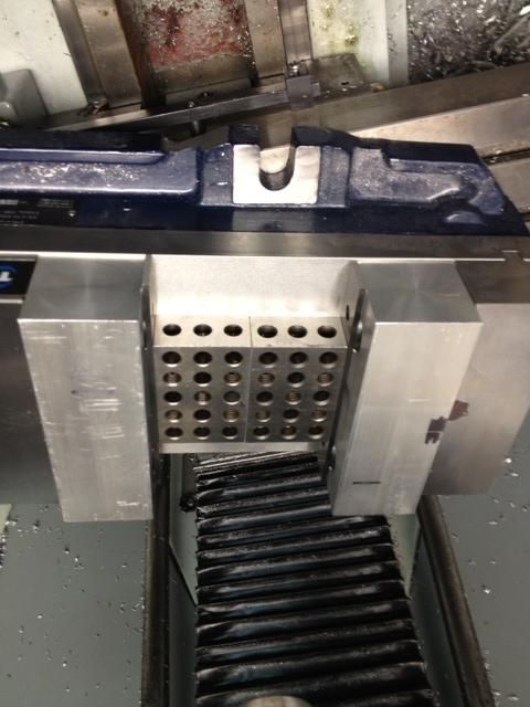
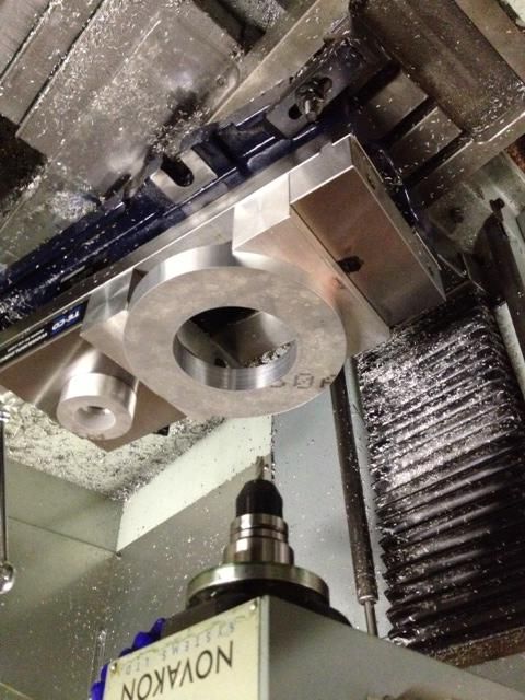
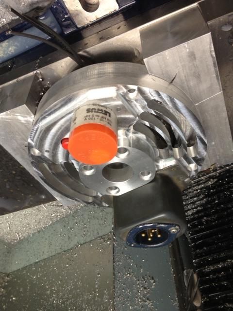
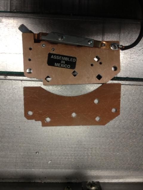
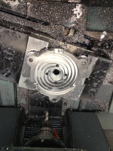
First run of parts completed. Here's some pics of them. I know these parts are probably easy for a seasoned veteran to do in his sleep. I am proud of this accomplishment and will keep moving upward in diffficulty I am sure.
-
03-27-2013, 09:08 PM #27
Registered
- Join Date
- Jul 2007
- Posts
- 675
Looking good!
-
05-17-2013, 04:33 PM #28
Registered
- Join Date
- Jul 2010
- Posts
- 41
 more pics
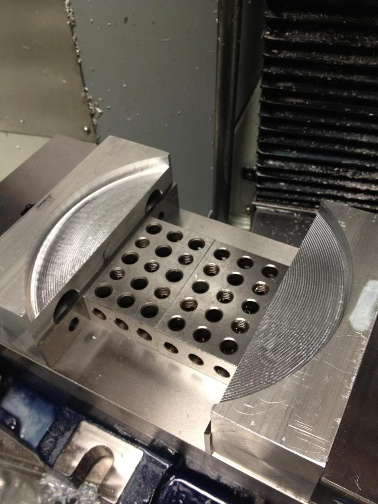
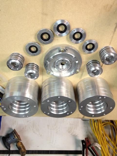
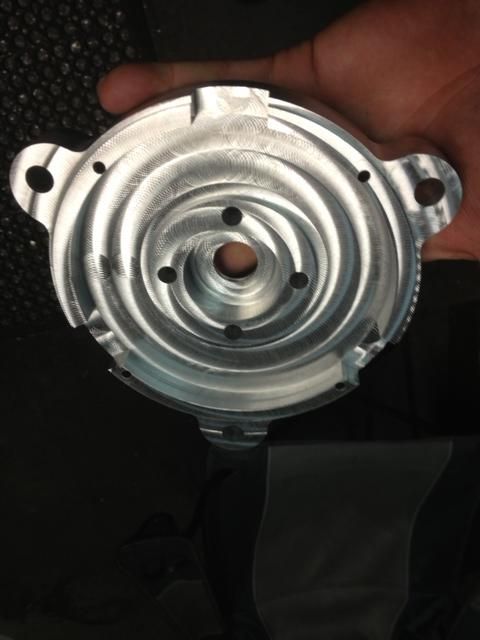
In the last 6 weeks I have learned alot about the mill and mach3 and its capabilities. Here are some more parts that I got done.
-
05-17-2013, 04:39 PM #29
Registered
- Join Date
- Jul 2010
- Posts
- 41
 a few more pics
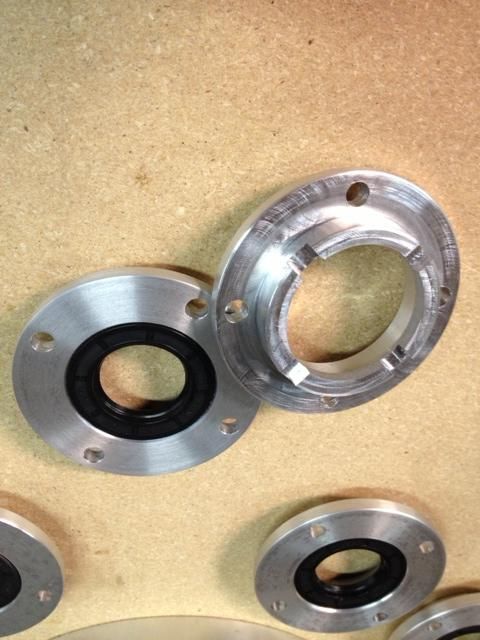
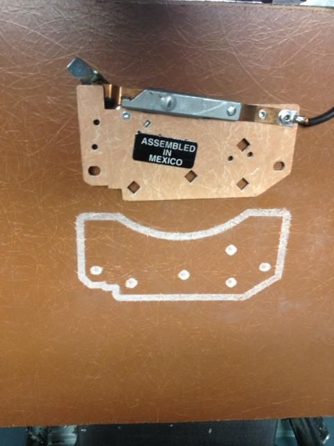
I am getting ready to make a hold down plate for the table now. Ordered in two pieces of waterjetted 6061 aluminum plate now to lay it out and start drilling and tapping a bunch of holes.
-
05-17-2013, 05:49 PM #30
Gold Member
- Join Date
- Sep 2006
- Posts
- 1738
Don't know what it is but nice job.
-Jason
-
05-17-2013, 06:17 PM #31
Registered
- Join Date
- Jul 2010
- Posts
- 41
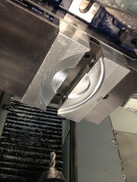
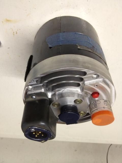
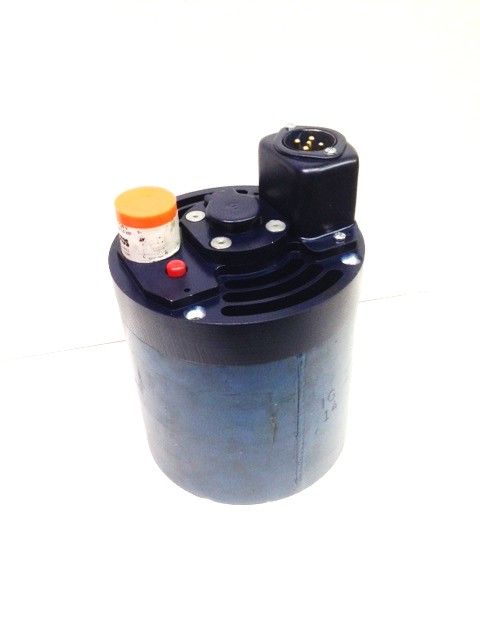
They are electric motor components for to convert 50 year old motors over to up to date motors and also upgrade from mechanical switch style to solid state switch technology. for the machines that I work with and service. will be taking these to a trade show in about 2 weeks
-
05-17-2013, 06:19 PM #32
Member
- Join Date
- Jun 2008
- Posts
- 1082
Yeah, very nice!
-
05-17-2013, 07:35 PM #33
Gold Member
- Join Date
- Sep 2006
- Posts
- 1738
You should get them anodized...
Wink Wink Wink
EDIT. Wait you do....fail by me
-
05-17-2013, 08:05 PM #34
Registered
- Join Date
- Feb 2010
- Posts
- 371
Very Nice!
-
05-17-2013, 08:22 PM #35
Registered
- Join Date
- May 2013
- Posts
- 99
I am computer guy. Why don,t you put your electronics into any casings?
Sent from my XT897 using Tapatalk 2
-
05-19-2013, 04:25 AM #36
Registered
- Join Date
- Jul 2010
- Posts
- 41
The electronics is already in its own housing which is the orange cover that you see. The terminal board is just a junction point for existing terminals to tie them together.

 Reply With Quote


Similar Threads
-
Has anyone purchased a NM-200 S3?
By MRM RCModels in forum NovakonReplies: 8Last Post: 02-29-2012, 02:01 PM -
just purchased 325
By chineshop_guy in forum TreeReplies: 1Last Post: 03-21-2011, 03:40 AM -
Just purchased a copy of XR3 MP.
By l u k e in forum OneCNCReplies: 6Last Post: 11-27-2008, 07:56 PM -
What have I purchased?
By vacpress in forum Phase ConvertersReplies: 8Last Post: 05-26-2006, 06:33 PM -
just purchased new tl-3
By qualitytool in forum Haas MillsReplies: 8Last Post: 03-30-2006, 08:01 PM
