


My extruder experiment came out great and so I decided to go ahead and build a dedicated 3D printer
http://www.cnczone.com/forums/genera...c_machine.html
Build specs
8 x 8 x 8 inch print bed
Frame is 1 inch T slot
Bearings are T sot linear bearings - no screws, no smooth rods
GT2 drive pulleys and belts'
Nema 17 motors
Probotix drivers, breakout board and power supply
gnex lab dual temp control board for hot end and heater bed
8 inch silicon heater bed
I will run the code on Mach3
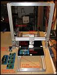
I cut the T slot pices today and did a rough fit to see how it looks
I don't have the UHMW-PE bearing material for my bearing blocks yet and so I just used cardboard for the mock up
Here's a pic of the progress so far
Thread: New printer build
Results 1 to 20 of 21
-
03-08-2013, 11:26 PM #1
 Member
- Join Date
- Jul 2007
- Posts
- 189
New printer build
-
03-10-2013, 10:06 PM #2
Member
- Join Date
- Jul 2007
- Posts
- 189
I got the X axis up and running today and took a movie of it in action
(The 3D printer crowd calls this the Y axis)
Still waiting on the UHMW-PE bearing material for my bearing blocks
I should have the bearing material here in a couple days
The bearing blocks have some cardboard in them for this test
I should be able to crank up the motor speed in Mach3 when I remove the cardboard and have the linear bearings dialed it
I machined a Nema 17 raised motor mount from G10 and made the idler pulley bearing assembly from scratch
Under the 9 x 9 bed is a couple GT2 belt clamps that I machined from G10
I am using a spring to keep tension on the cut belt but I need to get a stronger spring
Here's a few pics and a movie
-
03-13-2013, 12:02 AM #3
Member
- Join Date
- Jul 2007
- Posts
- 189
I installed the UHMW-PE bearing material in the bearing blocks and got the X and Z axis up and running
The X axis has a spring under the bed that keeps the belt tensioned
The Z axis has two shafts with two GT2 pulleys and belts
The bottom shaft is the drive shaft and the top shaft just free wheels
I can slide the top shaft up or down to put tension on the belts
Here's a video of both axis running some G code
-
03-14-2013, 10:43 PM #4
Member
- Join Date
- Jul 2007
- Posts
- 189
Got the Y axis running today.
Got to tidy up the electronics and then on to the A axis extruder
-
03-14-2013, 10:46 PM #5
Community Moderator
- Join Date
- Mar 2003
- Posts
- 6855
Im loven it look great!
-
03-14-2013, 11:05 PM #6
Member
- Join Date
- Jul 2007
- Posts
- 189
Thanks Paul
The linear bearings are gonna work out great I think
They are a bit tricky to set up, but not difficult
You have to shim the backside of the bearing material using .005 inch shims to remove all the play
There are 3 bearings per bearing block like in this pic
-
03-14-2013, 11:33 PM #7
Gold Member
- Join Date
- Jun 2004
- Posts
- 6618
That is looking very cool.
Lee
-
03-15-2013, 12:38 AM #8
Member
- Join Date
- Jul 2007
- Posts
- 189
Thanks Lee. It's a ton of work, but fun and challenging
-
03-16-2013, 07:56 PM #9
Member
- Join Date
- Jul 2007
- Posts
- 189
I just ran the Gcode on the new printer for the small cup I made in my extruder test
http://www.cnczone.com/forums/genera...c_machine.html
My CNC machine took over 1.5 hours to complete the cup
The new machine did it in 32 minutes and there is still room to crank up the motor speeds in Mach3
A second run with some dialed in settings in slic3r finished in 25 minutes
-
03-20-2013, 09:34 PM #10
Member
- Join Date
- Jul 2007
- Posts
- 189
I spent a couple days getting everything square, bolting down the electronics and got the A axis extruder almost done.
Here's a video of the 3D printer running the same cup code I did on my CNC machine extruder test.
The 3D printer is finishing the same code in 25 minutes that my CNC machine did in 1 hour 40 minutes
It hard to see just how fast the X and Y axis are in this video but if you lay your hand on the X axis bed, it feels like an intense vibration as it rips the code off in Mach3
I should have the extruder finished in the next couple days and be ready to print the cup code to compare it to what my CNC machine printed
-
03-27-2013, 02:59 PM #11
Member
- Join Date
- Jul 2007
- Posts
- 189
I have been pecking away at the printer build
All 4 axis are dialed in and calibrated in mach3
I built a ball bearing filament spool dispenser at the top of the machine
I built a glass plate work surface
I made a bunch of improvements to the extruder
I added a 40mm fan to the extruder
I added a touch probe to zero out the work surface
I am currently adding limit switches.
I'll take some detailed images once I have everything in place
Here's a complex shape I printed and a pic of the machine
-
03-27-2013, 05:08 PM #12
Gold Member
- Join Date
- Mar 2006
- Posts
- 119
Hey Doug, great work- subscribed!
Thanks for sharing the details of your builds.
MikeExpensive tools can be cheaper than professional therapy
-
03-27-2013, 05:30 PM #13
Member
- Join Date
- Jul 2007
- Posts
- 189
Hey Mike,
I'll try and get some good detailed pics of the build soon
-
03-29-2013, 01:48 AM #14
Member
- Join Date
- Jul 2007
- Posts
- 189
I finally had some time today to take a bunch of detailed pictures of the 3D printer
I have added several things to the printer since I last posted here
This page on my web site has lots of pics and info
My 3D Printer build page
Check out this twisted cup shape I printed
http://www.el34world.com/Misc/Cnc/images/IMG_7485.JPG
Here's an small image of the printer
Go to the link above to see large detailed images
-
03-29-2013, 06:28 AM #15
Gold Member
- Join Date
- Mar 2006
- Posts
- 119
Wow man, great site- I will definitely soak up all the info. I really like that homegrown extruder too.
Thanks, MikeExpensive tools can be cheaper than professional therapy
-
03-29-2013, 10:48 AM #16
Member
- Join Date
- Jul 2007
- Posts
- 189
Thanks Mike
-
04-10-2013, 03:01 PM #17
Member
- Join Date
- Jul 2007
- Posts
- 189
After using the 3D printer for a couple weeks, I made some improvements to the extruder.
The filament tension arm was hard to grab hold of and swing out because the tension spring is very strong
And so I added a finger indent that makes it easy to swing out and load filament
I made the tension swing arm a bit fatter at the top so I could use fender washers and get a more stable pivot point
I added an On-Off switch and a LED indicator
The switch turns on the 40mm fan and the extruder
I added an eye bolt at the top to keep the filament aligned with the filament gear and idler bearing
The fan swings out of the way and uses a wingnut to lock it in place
The idler bearing is a 5mm sealed bearing with an outer shell added that has a groove machined into it
Here's a couple pic of the extruder upgrades
-
04-29-2013, 08:02 PM #18
Member
- Join Date
- Jul 2007
- Posts
- 189
I changed out the nozzle on my printer
The brass acorn nut was dragging material around and there was not enough brass on the end to be able to machine it down to a finer point
I purchased a makerbot style .4 mm nozzle and the prints are much cleaner now
I printed this skull in 4 parts and glued them together
I added some LED's behind the eye sockets just for fun
The lid comes off just above the eyebrows for access to the electronics
I added a few pics of some of the prints here
3D prints page
-
05-12-2013, 12:39 AM #19
Gold Member
- Join Date
- May 2006
- Posts
- 2420
Great work ! I have been trolling through the net looking for info on 3d printing (stupid me looked everywhere except the zone (chair) ) and your build log just made everything a lot clearer.
Just a couple of things I am still unsure about, what is the extruder clearance from the surface being printed ? Lets say you are using a 0.35mm nozzle (sorry for the metric) do you keep the nozzle the same distance above or is there a rule of thumb to use ?
Also I was going to do the same thing as you and try it out on my router first then build a dedicated machine that is faster, even though I am building a new router that will pretty much fly...is there a maximum speed for printing or is the sky the limit ?
I literally have a bucket of servo's lying around and enough electronics to create smoke so I may be better off building a machine from scratch eventually, just want to prove the concept first. Apart from slow printing is there any issue with using the old router for starters ?
Cheers.
Russell.
-
05-12-2013, 01:30 AM #20
Member
- Join Date
- Jul 2007
- Posts
- 189
Hi Russ,
I just touch the extruder tip onto the blue tape surface and set mach3 to zero Z
When you print an object, you can specify an outer ring to print so many times before it starts the actual print
You can see if you are laying down the plastic properly or not
If not, just stop the print, adjust the nozzle up or down, set Z to zero and start again
It's hard to use a metal touch down like you can on your router because the extruder tip always has some melted plastic on it and so a metal touch plate does not work really well.
I put a strong light on the bed and adjust Z zero by eye
You want a tiny gap, maybe .2mm is all

 Reply With Quote
Similar Threads
-
Build your own large format printer?
By rackbox in forum Printing, Scanners, Vinyl cutting and PlottersReplies: 15Last Post: 09-22-2016, 06:25 PM -
RapMan 3d Printer Build Video
By robyward in forum VideosReplies: 5Last Post: 12-01-2012, 12:05 PM -
custom 3d printer build
By fritzgutten in forum 3D Printer / 3D Scanner DiscussionReplies: 11Last Post: 11-27-2012, 08:40 PM -
NO PRINTER PORT .HELP for my g0704 build.
By macatoms in forum Benchtop MachinesReplies: 4Last Post: 02-17-2011, 10:56 AM -
Need to build a printer for glass and plastic
By originator in forum Printing, Scanners, Vinyl cutting and PlottersReplies: 4Last Post: 11-03-2008, 01:22 PM
